EP0963809A2 - Dispositif pour la synchronisation du déplacement de différents modules téléscopiques - Google Patents
Dispositif pour la synchronisation du déplacement de différents modules téléscopiques Download PDFInfo
- Publication number
- EP0963809A2 EP0963809A2 EP98500277A EP98500277A EP0963809A2 EP 0963809 A2 EP0963809 A2 EP 0963809A2 EP 98500277 A EP98500277 A EP 98500277A EP 98500277 A EP98500277 A EP 98500277A EP 0963809 A2 EP0963809 A2 EP 0963809A2
- Authority
- EP
- European Patent Office
- Prior art keywords
- telescopic
- levers
- units
- movement
- move
- Prior art date
- Legal status (The legal status is an assumption and is not a legal conclusion. Google has not performed a legal analysis and makes no representation as to the accuracy of the status listed.)
- Withdrawn
Links
- 210000000056 organ Anatomy 0.000 claims description 3
- 239000002245 particle Substances 0.000 claims description 3
- 230000001360 synchronised effect Effects 0.000 claims description 3
- 239000007788 liquid Substances 0.000 claims description 2
- 238000000151 deposition Methods 0.000 claims 1
- 238000005755 formation reaction Methods 0.000 abstract 1
- 238000011084 recovery Methods 0.000 description 2
- 230000001133 acceleration Effects 0.000 description 1
- 239000002826 coolant Substances 0.000 description 1
- 230000008878 coupling Effects 0.000 description 1
- 238000010168 coupling process Methods 0.000 description 1
- 238000005859 coupling reaction Methods 0.000 description 1
- 230000008021 deposition Effects 0.000 description 1
- 239000000126 substance Substances 0.000 description 1
Images

Classifications
-
- B—PERFORMING OPERATIONS; TRANSPORTING
- B23—MACHINE TOOLS; METAL-WORKING NOT OTHERWISE PROVIDED FOR
- B23Q—DETAILS, COMPONENTS, OR ACCESSORIES FOR MACHINE TOOLS, e.g. ARRANGEMENTS FOR COPYING OR CONTROLLING; MACHINE TOOLS IN GENERAL CHARACTERISED BY THE CONSTRUCTION OF PARTICULAR DETAILS OR COMPONENTS; COMBINATIONS OR ASSOCIATIONS OF METAL-WORKING MACHINES, NOT DIRECTED TO A PARTICULAR RESULT
- B23Q11/00—Accessories fitted to machine tools for keeping tools or parts of the machine in good working condition or for cooling work; Safety devices specially combined with or arranged in, or specially adapted for use in connection with, machine tools
- B23Q11/08—Protective coverings for parts of machine tools; Splash guards
- B23Q11/0825—Relatively slidable coverings, e.g. telescopic
-
- B—PERFORMING OPERATIONS; TRANSPORTING
- B23—MACHINE TOOLS; METAL-WORKING NOT OTHERWISE PROVIDED FOR
- B23Q—DETAILS, COMPONENTS, OR ACCESSORIES FOR MACHINE TOOLS, e.g. ARRANGEMENTS FOR COPYING OR CONTROLLING; MACHINE TOOLS IN GENERAL CHARACTERISED BY THE CONSTRUCTION OF PARTICULAR DETAILS OR COMPONENTS; COMBINATIONS OR ASSOCIATIONS OF METAL-WORKING MACHINES, NOT DIRECTED TO A PARTICULAR RESULT
- B23Q11/00—Accessories fitted to machine tools for keeping tools or parts of the machine in good working condition or for cooling work; Safety devices specially combined with or arranged in, or specially adapted for use in connection with, machine tools
- B23Q11/08—Protective coverings for parts of machine tools; Splash guards
- B23Q2011/0808—Means for maintaining identical distances between relatively movable cover parts
Definitions
- the present invention relates to a device which allows to synchronize the movement carried out by several recovery units of a vital organ of a machine in avoiding the deposition of particles or liquids on parts that can become clogged.
- cover units move in one telescopic deployment and folding movement in depending on the actuation of the machine itself or a any of its elements; the movement of different units is performed by motors, or by hydraulic or pneumatic actuating cylinders.
- This device includes a series of two levers mounted in 'X', whose central rotation point is fixed on one of the intermediate telescopic units, coupling by its ends to another set of levers equivalent to the previous one and to the respective units located at the front and back of the one mentioned above.
- the points of union between the sets of levers in 'X' successive are constituted by cams which move longitudinally along defined windows laterally, so that all of the units when their telescopic movement remain synchronized and move in unison, both in their deployment and in their folding, thanks to the connection established by the games successive levers that link them.
- the side windows in which move the articulation points of two sets of levers consecutive are defined by additional documents laterally fixed in the telescopic unit corresponding and have a pre-calculated length which determines the extreme positions, the maximum deployment and minimum between telescopic units.
- the different telescopic units have inside, lateral bearings which act on the guides of the corresponding machine, allowing a telescopic movement at high speed.
- the unit located first which hides the units telescopic when they fold up and cannot be removed, has smaller sets of matching levers size than the previous ones which are articulated in a point central and at the end with the first set of levers so as to synchronize the movement of the second telescopic unit.
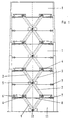
- the device shown in the figures performs this operation by synchronizing the movement of different units (1); it includes for this a series of levers (2) and (3), mounted in 'X', the point of central rotation (5) is fixed on one of the units telescopic intermediate (1) and whose ends (4) mate to another set of 'X' levers equivalent to previous and to the respective units (1) located at the front and at the back of the one mentioned above.
- Dots of union (4) between two consecutive scissor games (2-3) form cams which move longitudinally in windows (6) defined laterally, so that the set of units (1) during their movement telescopic stay synchronized and move at in unison, both during their deployment and their folding, thanks to the union established between units by the successive sets of levers that link them.
- the windows (6) in which the points of articulation (4) between two sets of levers (2-3) consecutive, are defined by additional documents laterally fixed in the telescopic unit (1) corresponding.
- Each of these windows presents a pre-calculated length which determines the extreme positions and the maximum and minimum deployment between units telescopic (1).
- the different telescopic units (1) present the inside of the side bearings (7), mounted on transverse sheets (8) which act on the guides of the corresponding machine, allowing movement telescopic at high speed.
- These bearings (7) coincide in the practical example shown, with the intersection points (6) of each chisel and with the ends (4) of these and also in the same area of each telescopic unit (1), preferably with the area furthest forward or located closest to the fixed part of the machine.
Landscapes
- Engineering & Computer Science (AREA)
- Mechanical Engineering (AREA)
- Catching Or Destruction (AREA)
- Infusion, Injection, And Reservoir Apparatuses (AREA)
- Mechanical Control Devices (AREA)
- Accommodation For Nursing Or Treatment Tables (AREA)
Abstract
Description
Claims (4)
- Dispositif pour la synchronisation du déplacement de différents modules télescopiques, de préférence d'unités de recouvrement (1) d'un organe vital d'une machine en évitant le dépôt de particules ou de liquides sur des pièces pouvant se boucher, caractérisé en ce qu'il comprend une série de leviers (2) et (3) montés en 'X', dont le point de rotation central (5) est fixé sur une des unités télescopiques intermédiaires (1) et dont les extrémités (4) s'accouplent à un autre jeu de leviers en 'X' équivalent au précédent et aux unités respectives (1) situées à l'avant et à l'arrière de celui mentionné précédemment, ces points d'union (4) constituant des cames qui se déplacent longitudinalement le long de fenêtres (6) définies latéralement de sorte que l'ensemble des unités (1) dans leur déplacement télescopique, demeurent synchronisées et se déplacent à l'unisson, tant lors de leur déploiement que de leur repliement, grâce à l'union établie par les jeux successifs de leviers qui les lient.
- Dispositif, selon la revendication précédente, caractérisé en ce que les fenêtres (6) dans lesquelles se déplacent les points d'articulation (4) entre deux jeux de leviers (2-3) consécutifs, sont définies par des pièces complémentaires fixées latéralement dans l'unité télescopique (1) correspondante et présentent une longueur précalculée qui détermine les positions extrêmes et le déploiement maximum et minimum entre unités télescopiques (1).
- Dispositif, selon les revendications précédentes, caractérisé en ce que les différentes unités télescopiques (1) présentent à l'intérieur des roulements latéraux (7) qui agissent sur les guides de la machine correspondante, permettant un déplacement télescopique à grande vitesse.
- Dispositif, selon les revendications précédentes, caractérisé en ce que l'unité (11) inamovile qui cache les unités télescopiques (1) quand elles se déplient, présente deux jeux de leviers (9) qui s'articulent en un point central (10) et à l'extrémité (4) avec le premier jeu de leviers (2-3) afin de synchroniser de même le déplacement de la deuxième unité télescopique (1).
Applications Claiming Priority (2)
| Application Number | Priority Date | Filing Date | Title |
|---|---|---|---|
| ES009800994A ES2163943B1 (es) | 1998-05-12 | 1998-05-12 | Dispositivo para sincronizacion del desplazamiento de diferentes modulos telescopicos. |
| ES9800994 | 1998-05-12 |
Publications (2)
| Publication Number | Publication Date |
|---|---|
| EP0963809A2 true EP0963809A2 (fr) | 1999-12-15 |
| EP0963809A3 EP0963809A3 (fr) | 2001-10-04 |
Family
ID=8303757
Family Applications (1)
| Application Number | Title | Priority Date | Filing Date |
|---|---|---|---|
| EP98500277A Withdrawn EP0963809A3 (fr) | 1998-05-12 | 1998-12-16 | Dispositif pour la synchronisation du déplacement de différents modules téléscopiques |
Country Status (2)
| Country | Link |
|---|---|
| EP (1) | EP0963809A3 (fr) |
| ES (1) | ES2163943B1 (fr) |
Cited By (11)
| Publication number | Priority date | Publication date | Assignee | Title |
|---|---|---|---|---|
| EP1232833A1 (fr) * | 2001-01-25 | 2002-08-21 | Greg Wang | Couvercle pour protection contre la poussière muni de leviers de guidage |
| EP1262277A1 (fr) * | 2001-05-31 | 2002-12-04 | Greg Wang | Couvercle pour protection contre la poussière muni d'éléments avec mouvements paralleles et simultanés |
| EP1329285A1 (fr) * | 2002-01-18 | 2003-07-23 | HEMA Maschinen- und Apparateschutz GmbH | Structure de stabilisation articulée pour un capot de protection |
| JP2006130648A (ja) * | 2004-11-08 | 2006-05-25 | Keyarrow Taiwan Co Ltd | 多重連接ロッド式防塵カバー |
| EP1728588A1 (fr) * | 2005-05-31 | 2006-12-06 | P.E.I. Protezioni Elaborazioni Industriali S.r.l. | Dispositif de protection et de recouvrement pour machines et pour systèmes |
| EP1738867A1 (fr) * | 2005-07-01 | 2007-01-03 | Keyarrow (Taiwan) Co., Ltd. | Couvercle télescopique multiliaison |
| US7600552B2 (en) | 2004-11-08 | 2009-10-13 | Keyarrow (Taiwan) Co., Ltd. | Multi-link telescopic cover |
| WO2013144688A1 (fr) | 2012-03-30 | 2013-10-03 | P.E.I. Protezioni Elaborazioni Industriali S.R.L. | Couvercle de protection télescopique |
| WO2014020453A1 (fr) | 2012-07-31 | 2014-02-06 | P.E.I. Protezioni Elaborazioni Industriali S.R.L. | Capot de protection télescopique |
| DE102010006220B4 (de) * | 2009-07-21 | 2015-10-08 | Nabell Corporation | Teleskopische Abdeckung |
| CN107363626A (zh) * | 2017-07-05 | 2017-11-21 | 宁夏共享机床辅机有限公司 | 一种高速平行同动机构导轨防护罩 |
Family Cites Families (6)
| Publication number | Priority date | Publication date | Assignee | Title |
|---|---|---|---|---|
| GB191229559A (en) * | 1912-12-23 | 1913-09-11 | Edward Williams | Improvements relating to Guards for Machine Tools and analogous purposes. |
| DE954304C (de) * | 1953-04-25 | 1956-12-13 | Arnold Hennig | Zum Schutz der Fuehrungsbahnen von hin- und hergehenden Teilen an Werkzeugmaschinen dienende Abdeckung |
| FR1576930A (fr) * | 1967-12-14 | 1969-08-01 | ||
| SU1154073A1 (ru) * | 1984-02-06 | 1985-05-07 | Минское станкостроительное производственное объединение им.Октябрьской революции | Устройство дл защиты направл ющих |
| DE3810645C1 (en) * | 1988-03-29 | 1988-12-22 | Kurt Kerren Laermschutztechnik Gmbh, 4060 Viersen, De | Opening device |
| SU1572787A1 (ru) * | 1988-04-12 | 1990-06-23 | Московское производственное объединение "Станкостроительный завод им.Серго Орджоникидзе" | Устройство дл защиты направл ющих станка с двум подвижными суппортами |
-
1998
- 1998-05-12 ES ES009800994A patent/ES2163943B1/es not_active Expired - Fee Related
- 1998-12-16 EP EP98500277A patent/EP0963809A3/fr not_active Withdrawn
Cited By (11)
| Publication number | Priority date | Publication date | Assignee | Title |
|---|---|---|---|---|
| EP1232833A1 (fr) * | 2001-01-25 | 2002-08-21 | Greg Wang | Couvercle pour protection contre la poussière muni de leviers de guidage |
| EP1262277A1 (fr) * | 2001-05-31 | 2002-12-04 | Greg Wang | Couvercle pour protection contre la poussière muni d'éléments avec mouvements paralleles et simultanés |
| EP1329285A1 (fr) * | 2002-01-18 | 2003-07-23 | HEMA Maschinen- und Apparateschutz GmbH | Structure de stabilisation articulée pour un capot de protection |
| JP2006130648A (ja) * | 2004-11-08 | 2006-05-25 | Keyarrow Taiwan Co Ltd | 多重連接ロッド式防塵カバー |
| US7600552B2 (en) | 2004-11-08 | 2009-10-13 | Keyarrow (Taiwan) Co., Ltd. | Multi-link telescopic cover |
| EP1728588A1 (fr) * | 2005-05-31 | 2006-12-06 | P.E.I. Protezioni Elaborazioni Industriali S.r.l. | Dispositif de protection et de recouvrement pour machines et pour systèmes |
| EP1738867A1 (fr) * | 2005-07-01 | 2007-01-03 | Keyarrow (Taiwan) Co., Ltd. | Couvercle télescopique multiliaison |
| DE102010006220B4 (de) * | 2009-07-21 | 2015-10-08 | Nabell Corporation | Teleskopische Abdeckung |
| WO2013144688A1 (fr) | 2012-03-30 | 2013-10-03 | P.E.I. Protezioni Elaborazioni Industriali S.R.L. | Couvercle de protection télescopique |
| WO2014020453A1 (fr) | 2012-07-31 | 2014-02-06 | P.E.I. Protezioni Elaborazioni Industriali S.R.L. | Capot de protection télescopique |
| CN107363626A (zh) * | 2017-07-05 | 2017-11-21 | 宁夏共享机床辅机有限公司 | 一种高速平行同动机构导轨防护罩 |
Also Published As
| Publication number | Publication date |
|---|---|
| ES2163943A1 (es) | 2002-02-01 |
| ES2163943B1 (es) | 2003-02-16 |
| EP0963809A3 (fr) | 2001-10-04 |
Similar Documents
| Publication | Publication Date | Title |
|---|---|---|
| EP0269653A1 (fr) | Dispositif permettant la correction des irregularites ou l'elargissement d'une conduite souterraine. | |
| EP2893171B1 (fr) | Boite d'engrenages de prise de mouvement sur une turbomachine, composée d'une chaîne cinématique a lignes d'engrenages s'étendant dans des plans non parallèles | |
| FR2531420A1 (fr) | Poussoir de recipients en verre | |
| EP0491071A1 (fr) | Machine à former par étirage | |
| FR2862988A1 (fr) | Dispositif d'aiguilletage d'un matelas de fibres | |
| EP0095795B2 (fr) | Machine perfectionnée pour la réalisation de galeries souterraines | |
| EP1409907A1 (fr) | Chariot porte-outil, notamment mobile dans une canalisation | |
| EP0963809A3 (fr) | Dispositif pour la synchronisation du déplacement de différents modules téléscopiques | |
| FR2966070A1 (fr) | Dispositif de manutention d'une charge notamment d'un outil de presse | |
| WO1992005046A1 (fr) | Dispositif pour le transfert de fonds entre un vehicule blinde et un batiment | |
| EP2678264B1 (fr) | Dispositif de transfert d'une charge par poussee et traction et engin de manutention equipe d'un tel dispositif | |
| FR2460167A1 (fr) | Procede et dispositif d'estampage et de pliage d'un materiau en bande et/ou en fil | |
| EP0626225B1 (fr) | Dispositif de transmission différentielle de force et de course pour un appareil de maintien de pièces mécaniques | |
| FR2639892A1 (fr) | Dispositif pour guider l'extraction et l'insertion d'un vantail dans son cadre, et porte, notamment ferroviaire, ainsi equipee | |
| FR2919842A1 (fr) | Dispositif de reglage pour la position d'un tableau de bord et d'un volant associe | |
| FR2781118A1 (fr) | Equipement d'ensileuse | |
| CA2150534C (fr) | Dispositif mecanique d'ejection comportant un piston mobile commande aller-retour | |
| CH655333A5 (fr) | Machine roulante pour excaver le ballast des voies ferrees. | |
| FR2664919A1 (fr) | Vehicule a moteur, en particulier vehicule a roues ou a chenilles, pour le transport et la mise en place d'un pont demontable. | |
| EP0781503B1 (fr) | Véhicule agricole dont les organes de travail assujettis à une poutre portée par un châssis peuvent être déplacés entre une position de travail et une position de route de moindre encombrement | |
| WO1991015942A1 (fr) | Bati de charrue du type comportant au moins un corps a versoir et soc unique travaillant dans les deux sens de labour | |
| EP2010720B1 (fr) | Dispositif de couplage d'un outil à la flèche d'un engin tel qu'une pelle hydraulique | |
| FR2654968A1 (fr) | Machine de rodage par expansion d'alesages. | |
| FR2749128A1 (fr) | Machine de recolte, en particulier moissonneuse-batteuse, comprenant un outil frontal compose d'au moins deux parties repliables | |
| FR2659993A1 (fr) | Rampe d'epandage a deploiement telescopique a buses orientees pour la realisation de revetements routiers. |
Legal Events
| Date | Code | Title | Description |
|---|---|---|---|
| PUAI | Public reference made under article 153(3) epc to a published international application that has entered the european phase |
Free format text: ORIGINAL CODE: 0009012 |
|
| AK | Designated contracting states |
Kind code of ref document: A2 Designated state(s): AT BE CH CY DE DK ES FI FR GB GR IE IT LI LU MC NL PT SE Kind code of ref document: A2 Designated state(s): BE CH DE FR GB IT LI SE |
|
| AX | Request for extension of the european patent |
Free format text: AL;LT;LV;MK;RO;SI |
|
| PUAL | Search report despatched |
Free format text: ORIGINAL CODE: 0009013 |
|
| AK | Designated contracting states |
Kind code of ref document: A3 Designated state(s): AT BE CH CY DE DK ES FI FR GB GR IE IT LI LU MC NL PT SE |
|
| AX | Request for extension of the european patent |
Free format text: AL;LT;LV;MK;RO;SI |
|
| 17P | Request for examination filed |
Effective date: 20020228 |
|
| AKX | Designation fees paid |
Free format text: BE CH DE FR GB IT LI SE |
|
| 17Q | First examination report despatched |
Effective date: 20040206 |
|
| STAA | Information on the status of an ep patent application or granted ep patent |
Free format text: STATUS: THE APPLICATION IS DEEMED TO BE WITHDRAWN |
|
| 18D | Application deemed to be withdrawn |
Effective date: 20040617 |