EP0964104A2 - Ensemble des dispositifs anti-retours - Google Patents
Ensemble des dispositifs anti-retours Download PDFInfo
- Publication number
- EP0964104A2 EP0964104A2 EP99111148A EP99111148A EP0964104A2 EP 0964104 A2 EP0964104 A2 EP 0964104A2 EP 99111148 A EP99111148 A EP 99111148A EP 99111148 A EP99111148 A EP 99111148A EP 0964104 A2 EP0964104 A2 EP 0964104A2
- Authority
- EP
- European Patent Office
- Prior art keywords
- assembly
- mounting assembly
- housing
- bore
- wall
- Prior art date
- Legal status (The legal status is an assumption and is not a legal conclusion. Google has not performed a legal analysis and makes no representation as to the accuracy of the status listed.)
- Withdrawn
Links
Images


Classifications
-
- E—FIXED CONSTRUCTIONS
- E03—WATER SUPPLY; SEWERAGE
- E03B—INSTALLATIONS OR METHODS FOR OBTAINING, COLLECTING, OR DISTRIBUTING WATER
- E03B7/00—Water main or service pipe systems
- E03B7/07—Arrangement of devices, e.g. filters, flow controls, measuring devices, siphons or valves, in the pipe systems
- E03B7/077—Arrangement of backflow preventing devices
-
- E—FIXED CONSTRUCTIONS
- E03—WATER SUPPLY; SEWERAGE
- E03C—DOMESTIC PLUMBING INSTALLATIONS FOR FRESH WATER OR WASTE WATER; SINKS
- E03C1/00—Domestic plumbing installations for fresh water or waste water; Sinks
- E03C1/02—Plumbing installations for fresh water
- E03C1/10—Devices for preventing contamination of drinking-water pipes, e.g. means for aerating self-closing flushing valves
- E03C1/106—Devices for preventing contamination of drinking-water pipes, e.g. means for aerating self-closing flushing valves using two or more check valves
-
- E—FIXED CONSTRUCTIONS
- E03—WATER SUPPLY; SEWERAGE
- E03C—DOMESTIC PLUMBING INSTALLATIONS FOR FRESH WATER OR WASTE WATER; SINKS
- E03C1/00—Domestic plumbing installations for fresh water or waste water; Sinks
- E03C1/02—Plumbing installations for fresh water
- E03C1/10—Devices for preventing contamination of drinking-water pipes, e.g. means for aerating self-closing flushing valves
- E03C1/108—Devices for preventing contamination of drinking-water pipes, e.g. means for aerating self-closing flushing valves having an aerating valve
-
- F—MECHANICAL ENGINEERING; LIGHTING; HEATING; WEAPONS; BLASTING
- F16—ENGINEERING ELEMENTS AND UNITS; GENERAL MEASURES FOR PRODUCING AND MAINTAINING EFFECTIVE FUNCTIONING OF MACHINES OR INSTALLATIONS; THERMAL INSULATION IN GENERAL
- F16K—VALVES; TAPS; COCKS; ACTUATING-FLOATS; DEVICES FOR VENTING OR AERATING
- F16K15/00—Check valves
- F16K15/02—Check valves with guided rigid valve members
- F16K15/06—Check valves with guided rigid valve members with guided stems
- F16K15/063—Check valves with guided rigid valve members with guided stems the valve being loaded by a spring
- F16K15/066—Check valves with guided rigid valve members with guided stems the valve being loaded by a spring with a plurality of valve members
-
- F—MECHANICAL ENGINEERING; LIGHTING; HEATING; WEAPONS; BLASTING
- F16—ENGINEERING ELEMENTS AND UNITS; GENERAL MEASURES FOR PRODUCING AND MAINTAINING EFFECTIVE FUNCTIONING OF MACHINES OR INSTALLATIONS; THERMAL INSULATION IN GENERAL
- F16K—VALVES; TAPS; COCKS; ACTUATING-FLOATS; DEVICES FOR VENTING OR AERATING
- F16K15/00—Check valves
- F16K15/14—Check valves with flexible valve members
- F16K15/1401—Check valves with flexible valve members having a plurality of independent valve members
-
- Y—GENERAL TAGGING OF NEW TECHNOLOGICAL DEVELOPMENTS; GENERAL TAGGING OF CROSS-SECTIONAL TECHNOLOGIES SPANNING OVER SEVERAL SECTIONS OF THE IPC; TECHNICAL SUBJECTS COVERED BY FORMER USPC CROSS-REFERENCE ART COLLECTIONS [XRACs] AND DIGESTS
- Y10—TECHNICAL SUBJECTS COVERED BY FORMER USPC
- Y10T—TECHNICAL SUBJECTS COVERED BY FORMER US CLASSIFICATION
- Y10T137/00—Fluid handling
- Y10T137/6851—With casing, support, protector or static constructional installations
- Y10T137/7036—Jacketed
-
- Y—GENERAL TAGGING OF NEW TECHNOLOGICAL DEVELOPMENTS; GENERAL TAGGING OF CROSS-SECTIONAL TECHNOLOGIES SPANNING OVER SEVERAL SECTIONS OF THE IPC; TECHNICAL SUBJECTS COVERED BY FORMER USPC CROSS-REFERENCE ART COLLECTIONS [XRACs] AND DIGESTS
- Y10—TECHNICAL SUBJECTS COVERED BY FORMER USPC
- Y10T—TECHNICAL SUBJECTS COVERED BY FORMER US CLASSIFICATION
- Y10T137/00—Fluid handling
- Y10T137/7722—Line condition change responsive valves
- Y10T137/7837—Direct response valves [i.e., check valve type]
- Y10T137/7838—Plural
Definitions
- This invention relates to a backflow preventer.
- Backflow preventers are principally used for preventing contamination of a public water distribution system by preventing backflow or back-siphonage of contaminated water into the system.
- the backflow preventer assembly is installed in a pipeline between a main supply line and a service line that feeds an installation, e.g., hotels, factories or other institutions, or even a multi or single family residence.
- a backflow prevention assembly typically includes two check valves permitting flow only in the direction from the main supply line to the service line.
- a backflow preventer assembly includes a housing having a first end and a second end, a first mounting assembly configured for assembling by insertion with the first end of the housing, and a second mounting assembly configured for assembling by insertion with the second end of the housing.
- the housing includes a wall having an inner surface defining a through bore extending between the first and second ends.
- the first and second mounting assemblies each includes a wall having an inner surface defining a through bore in fluid communication with the housing through bore.
- Securing material secures opposed surfaces of the first mounting assembly and the housing, and opposed surfaces of the second mounting assembly and the housing.
- Plating material is located on the inner surfaces of the housing and mounting assemblies. The plating material forms a wall restricting migration of the securing material into the housing and mounting assembly bores.
- Embodiments of the invention may include one or more of the following features.
- the opposed surfaces include an outer surface of the first mounting assembly wall, an outer surface of the second mounting assembly wall, and an inner surface of the housing wall.
- the securing material is solder.
- the plating material is nickel.
- the first and second mounting assemblies each include an inner end and an outer end. The outer ends are threaded.
- a first ball valve assembly is threadedly attached to the outer end of the first mounting assembly, and a second ball valve assembly is threadedly attached to the outer end of the second mounting assembly.
- An outer surface of the housing wall, an outer surface of the first mounting assembly wall, an outer surface of the second mounting assembly wall, an outer surface of the first ball valve assembly, and an outer surface of the second ball valve assembly include plating material, e.g., nickel.
- Inner surfaces of the ball valve assemblies include plating material, e.g., nickel.
- a first check valve assembly is threadedly attached to the inner end of the first mounting assembly, and a second check valve assembly is threadedly attached to the inner end of the second mounting assembly.
- the housing wall defines a port.
- a cover closes the port.
- the backflow preventer assembly includes a plurality of test cocks.
- the backflow preventer assembly includes a pressure reduction assembly.
- a method of mounting ball valves and check valves to a backflow preventer includes securing opposed surfaces of a first mounting assembly and a housing with securing material; securing opposed surfaces of a second mounting assembly and the housing; and plating an inner surface of the housing, an inner surface of the first mounting assembly, and an inner surface of the second mounting assembly with plating material.
- the plating material forms a wall restricting migration of the securing material into the housing and mounting assembly bores.
- Ball valve assemblies are threadedly attached to outer ends of the first and second mounting assemblies.
- Check valve assemblies are threadedly attached to inner ends of the first and second mounting assemblies.
- Advantages of the invention include a backflow preventer assembly that is less expensive to manufacture than currently available backflow preventer assemblies for similar applications.
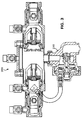
- a backflow preventer assembly 10 includes a housing 20 having a first end 22, a second end 24, and a wall 25.
- a through bore 30 extends between ends 22, 24 of housing 20 for flow of water therethrough.
- a pair of valve modules 40, 50 are located at ends 22, 24, respectively, of housing 20.
- Valve module 40 includes a mount 43, a ball valve assembly 60, e.g., Ball Valve Assembly Part No. FBV-E-775 available from Watts Industries, North Andover, Massachusetts, and a check valve assembly 80, e.g., Check Valve Assembly Part No. SA-775CA37 also available from Watts Industries.
- a through bore 48 defined by mount 43 and ball valve assembly 60 is in fluid communication with housing bore 30 when check valve assembly 80 is in an open, flow position.
- Mount 43 has an outer end 42, an inner end 44, and a wall 45 having an outer surface 47 and an inner surface 46. Inner end 44 of mount 43 steps down in diameter at a shoulder 44a to define a contact surface 32.
- mount 43 To secure mount 43 to housing 20, inner end 44 of mount 43 is inserted into first end 22 of housing 20, with contact surface 32 abutting an inner surface 26 of housing 20. Securing material 34, e.g., solder or brazen, is used to connect contact surface 32 to inner surface 26 of wall 25.
- solder or brazen Securing material 34
- Ball valve assembly 60 defines cooperating internal threads 242 for connecting ball valve assembly 60 to mount 43.
- An o-ring 243 is located between mount 43 and ball valve assembly 60 to prevent fluid leakage therebetween.
- Inner end 44 of mount 43 defines internal threads 224.
- Check valve assembly 80 defines cooperating external threads 225 for connecting check valve assembly 80 to mount 43.
- An o-ring 260 is located between mount 43 and check valve assembly 80 to prevent fluid leakage therebetween.
- Valve module 50 includes a mount 53, a ball valve assembly 70, e.g., Ball Valve Assembly Part No. FBV-775 also available from Watts Industries, and a check valve assembly 90, e.g., Check Valve Assembly Part No. SA-775CB37 also available from Watts Industries.
- a through bore 58 defined by mount 53 and ball valve assembly 70 is in fluid communication with bore 30 when check valve assembly 90 is in an open, flow position.
- Mount 53 has an outer end 52, an inner end 54, and a wall 55 having an outer surface 57 and an inner surface 56. Inner end 54 of mount 53 steps down in diameter at a shoulder 54a to define a contact surface 36.
- mount 53 To secure mount 53 to housing 20, inner end 54 of mount 53 is inserted into first end 22 of housing 20, with contact surface 36 abutting inner surface 26 of housing 20. Securing material 38, e.g., solder or brazen, is used to connect contact surface 36 to inner surface 26 of wall 25.
- Ball valve assembly 70 defines cooperating internal threads 252 for connecting ball valve assembly 70 to mount 43.
- An o-ring 253 is located between mount 43 and ball valve assembly 70 to prevent fluid leakage therebetween.
- Inner end 54 of mount 53 defines internal threads 234.
- Check valve assembly 90 defines cooperating external threads 235 for connecting check valve assembly 90 to mount 43.
- An o-ring 270 is located between mount 43 and check valve assembly 90 to prevent fluid leakage therebetween.
- Housing 20 defines a port 28 which provides access to bore 30 and check valve assemblies 80, 90.
- a lip 29 of housing 20 defines a region 301 (Fig. 2) for retaining fastening nuts 302 having an inner threaded bore 306.
- Port 28 is closed by securing a cover 27 to housing 20 with threaded fastening screws 300 which are received by nuts 302.
- a circumferential rim 31 of cover 27 defines a groove 303 in cover 27 in which an o-ring 305, e.g., made from Viton, is located to create a fluid-tight seal between cover 27 and lip 29.
- an assembly of mounts 43, 53, housing 20, and ball valve assemblies 60, 80 is plated.
- Inner surface 26 of housing 20, inner surface 46 of mount 43, inner surface 56 of mount 53, inner surface 76 of ball valve assembly 60, and inner 77 of ball valve assembly 80 are plated with, e.g., nickel, to form an inner wall 500.
- Ball valve assemblies 60, 80 are held in their open positions during the plating process, e.g., electroless nickel plating.
- Wall 500 acts to seal and restrict migration of securing material 34, 38 into bores 30, 48, and 58.
- Plating material e.g., nickel
- Plating material is also applied to an outer surface 26a of housing 20, to outer surfaces 47, 57 of mounts 43, 53, respectively, and to outer surfaces 47a, 57a of ball valve assemblies 60, 70, respectively, to form an outer wall 501.
- Wall 501 acts to seal and restrict migration of securing material 34, 38.
- Walls 500, 501 also function to minimize oxidation of backflow preventer assembly 10 and to assist in sealing small leaks.
- Check valve assemblies 80, 90 can be accessed for service and replacement through port 28.
- cover 27 is unscrewed from housing 20 and the check valve assembly is disengaged from its respective mount (43 or 53).
- a new or rebuilt check valve assembly is then inserted into back flow preventer assembly 10 through port 28 and engaged with the respective mount.
- Check valve assemblies 80, 90 are oriented in sequence to allow flow of water through bore 30 in a first direction, indicated by arrow, F, (Fig. 1) but to prevent back flow of water in the opposite direction.
- Check valve modules 80, 90 are biased in the opposite direction of F to exceed a predetermined threshold before the check valves are opened.
- potable water from the public water distribution system enters the backflow preventer assembly 10 at an end 42a of ball valve assembly 60.
- ball valve assemblies 60, 70 are open and that the supply pressure exceeds the predetermined threshold value biasing the check valve assemblies 80, 90 towards closed positions, the check valve assemblies open to allow water flow in through first end 42a of ball valve assembly 60, through bores 48, 30 and 58, and finally through an end 52a of ball valve assembly 70.
- ball valve assemblies 60, 70 are used to isolate backflow preventer assembly 10 from external water flow for either servicing check valve assemblies 80, 90, as described above, or testing water quality and pressure through a series of test ports 100, 110, 120, 130.
- a reduced pressure backflow preventer assembly 200 includes a pressure reduction assembly 210.
Landscapes
- Engineering & Computer Science (AREA)
- General Engineering & Computer Science (AREA)
- Health & Medical Sciences (AREA)
- Life Sciences & Earth Sciences (AREA)
- Hydrology & Water Resources (AREA)
- Public Health (AREA)
- Water Supply & Treatment (AREA)
- Mechanical Engineering (AREA)
- Check Valves (AREA)
- Valve Housings (AREA)
Applications Claiming Priority (2)
| Application Number | Priority Date | Filing Date | Title |
|---|---|---|---|
| US93678 | 1998-06-09 | ||
| US09/093,678 US6021805A (en) | 1998-06-09 | 1998-06-09 | Backflow preventer assembly |
Publications (2)
| Publication Number | Publication Date |
|---|---|
| EP0964104A2 true EP0964104A2 (fr) | 1999-12-15 |
| EP0964104A3 EP0964104A3 (fr) | 2000-11-29 |
Family
ID=22240181
Family Applications (1)
| Application Number | Title | Priority Date | Filing Date |
|---|---|---|---|
| EP19990111148 Withdrawn EP0964104A3 (fr) | 1998-06-09 | 1999-06-08 | Ensemble des dispositifs anti-retours |
Country Status (5)
| Country | Link |
|---|---|
| US (1) | US6021805A (fr) |
| EP (1) | EP0964104A3 (fr) |
| JP (1) | JP2000055219A (fr) |
| AU (1) | AU3395299A (fr) |
| CA (1) | CA2274265A1 (fr) |
Cited By (3)
| Publication number | Priority date | Publication date | Assignee | Title |
|---|---|---|---|---|
| EP1315927A4 (fr) * | 2000-09-07 | 2005-06-01 | Cmb Ind | Assemblage anti-retour a pression reduite et faible encombrement |
| WO2006008730A1 (fr) | 2004-07-21 | 2006-01-26 | A.R.I. Flow Control Accessories Ltd. | Dispositif anti-refoulement |
| AU2007100374B4 (en) * | 2006-05-08 | 2012-03-29 | Australian Valve Group Pty Ltd | Fluid Flow Control Device |
Families Citing this family (29)
| Publication number | Priority date | Publication date | Assignee | Title |
|---|---|---|---|---|
| US6325090B1 (en) * | 1998-06-09 | 2001-12-04 | Watts Investment Company | Backflow preventer assembly |
| CA2373393C (fr) * | 1999-05-18 | 2004-08-17 | Zurn Industries, Inc. | Clapet anti-retour |
| US6192933B1 (en) | 1999-12-03 | 2001-02-27 | Watts Investment Company | Backflow prevention assembly |
| US6478047B1 (en) * | 2001-01-05 | 2002-11-12 | Hunter Innovations, Inc. | Backflow prevention apparatus |
| US6581626B2 (en) | 2001-06-28 | 2003-06-24 | Zurn Industries, Inc. | Backflow prevention apparatus |
| PL359448A1 (en) * | 2002-04-03 | 2003-10-06 | Hans Sasserath & Co Kg | Set of isolating valves for water supply system |
| US20030188779A1 (en) * | 2002-04-09 | 2003-10-09 | Degarmo Plumbing, Inc. | Air gap mounting sink for a backflow prevention device |
| USD544073S1 (en) | 2003-04-08 | 2007-06-05 | Degarmo Plumbing, Inc. | Backflow prevention sink |
| US20050274414A1 (en) * | 2004-06-10 | 2005-12-15 | Po-Sung Kuo | Drain device for high negative pressure exhaust system |
| US8720648B1 (en) * | 2005-04-27 | 2014-05-13 | Coltec Industrial Products, LLC | Check valve and method and apparatus for extending life of check valves |
| US20070204916A1 (en) * | 2006-03-01 | 2007-09-06 | Rain Bird Corporation | Backflow prevention device |
| US20070204917A1 (en) * | 2006-03-01 | 2007-09-06 | Rain Bird Corporation | Backflow prevention device |
| ITTO20060177A1 (it) * | 2006-03-09 | 2007-09-10 | Eltek Spa | Dispositivo idraulico, apparecchiatura idraulica, impianto idraulico e metodo per il suo utilizzo |
| JP5081785B2 (ja) * | 2008-10-16 | 2012-11-28 | 前澤給装工業株式会社 | 逆止弁カートリッジの嵌装構造と逆止弁ユニット |
| US8240333B2 (en) * | 2009-07-07 | 2012-08-14 | Conbraco Industries, Inc. | Separator for a release valve |
| US9724457B2 (en) * | 2010-07-09 | 2017-08-08 | W.D. Manor Mechanical Contractors, Inc. | Dialysis service box |
| US9222334B2 (en) | 2011-06-17 | 2015-12-29 | Schlumberger Technology Corporation | Valve system for downhole tool string |
| ITRM20110384A1 (it) | 2011-07-20 | 2013-01-21 | Seko Spa | Valvola di disconnessione a membrana flessibile, in particolare per la prevenzione del riflusso. |
| US8875733B2 (en) * | 2012-12-04 | 2014-11-04 | Douglas Hunter Powell | Check valve in backflow prevention device |
| US9353742B2 (en) | 2014-10-01 | 2016-05-31 | Curtis Roys | Check valve |
| US9611980B2 (en) | 2014-10-01 | 2017-04-04 | Curtis Roys | Check valve |
| US10914412B2 (en) | 2018-06-28 | 2021-02-09 | Watts Regulator Co. | Backflow prevention assembly having a variable lay-length and orientation |
| US11815424B2 (en) | 2019-05-08 | 2023-11-14 | Watts Regulator Co. | Backflow prevention system test cock with a fluid sensor |
| US11795666B2 (en) | 2019-05-08 | 2023-10-24 | Watts Regulator Co. | Wireless communication system within a mechanical room |
| US12195954B2 (en) | 2019-12-10 | 2025-01-14 | Watts Regulator Co. | System for monitoring backflow preventer condition |
| EP3835494A1 (fr) | 2019-12-10 | 2021-06-16 | Watts Regulator Co. | Système de surveillance de l'état d'un disconnecteur hydraulique |
| US11719352B2 (en) | 2020-08-17 | 2023-08-08 | Watts Regulator Co. | Check cover assemblies for backflow prevention assemblies with integrated test cock protection shroud |
| USD1021000S1 (en) | 2021-08-17 | 2024-04-02 | Watts Regulator Co. | Valve assembly and body for same |
| US12460733B2 (en) | 2022-04-09 | 2025-11-04 | Curtis Alan Roys | Divider block system and balancing valve for divider block system |
Family Cites Families (20)
| Publication number | Priority date | Publication date | Assignee | Title |
|---|---|---|---|---|
| US3612096A (en) * | 1969-07-30 | 1971-10-12 | Murray Corp | Pilot operated flow control valve |
| US3812878A (en) * | 1971-09-27 | 1974-05-28 | Bird Corp | Fail-safe breathing circuit and valve assembly for use therewith |
| US3906987A (en) * | 1974-03-13 | 1975-09-23 | Watts Regulator Co | Swing open cross-connection valve |
| US4013088A (en) * | 1975-05-19 | 1977-03-22 | Braukmann Armaturen Ag | Valve structure |
| US4159025A (en) * | 1977-05-06 | 1979-06-26 | Telford L. Smith | Back flow preventer valve |
| US4232704A (en) * | 1978-03-28 | 1980-11-11 | Amtrol Inc. | In line back flow preventer |
| US4284097A (en) * | 1978-03-28 | 1981-08-18 | Amtrol Inc. | In line back flow preventer |
| US4231387A (en) * | 1979-01-11 | 1980-11-04 | Chas. M. Bailey Co., Inc. | Backflow preventing valve |
| US4333495A (en) * | 1979-02-09 | 1982-06-08 | Griswold Controls | Check valve assembly |
| EP0084754B2 (fr) * | 1982-01-26 | 1991-12-11 | SOCLA SA Société dite | Disconnecteur pour des canalisations hydrauliques |
| US4878515A (en) * | 1988-10-07 | 1989-11-07 | Stevens Robert B | Water access preventer |
| US4945940A (en) * | 1989-08-21 | 1990-08-07 | Stevens Robert B | Tamper proof backflow prevention assembly |
| US5226441A (en) * | 1989-11-13 | 1993-07-13 | Cmb Industries | Backflow preventor with adjustable outflow direction |
| US4991622A (en) * | 1989-12-19 | 1991-02-12 | Cmb Industries | Multiply configurable backflow preventer |
| US5046525A (en) * | 1990-06-15 | 1991-09-10 | Ames Company, Inc. | Differential loading fluid check valve |
| JP3119309B2 (ja) * | 1991-11-08 | 2000-12-18 | 東陶機器株式会社 | 水栓金具及びその内蔵部品の表面処理方法 |
| FR2709799B1 (fr) * | 1993-09-09 | 1995-10-27 | Top Ind Sa | Vanne d'arrêt de diamètre nominal millimétrique pour fluide sous haute pression. |
| DE4404194C2 (de) * | 1994-02-10 | 1996-04-18 | Reinecke Alfred Gmbh & Co Kg | Trinkwasserführende Armatur aus Metall, insbesondere aus Kupfer und dessen Legierungen mit Anteilen an Zink und Blei |
| US5566704A (en) * | 1995-01-06 | 1996-10-22 | Watts Investment Company | Backflow preventer and test cock assembly |
| US5584315A (en) * | 1995-12-18 | 1996-12-17 | Ames Company, Inc. | Check valve assembly and method for mounting and installing check valves within a housing |
-
1998
- 1998-06-09 US US09/093,678 patent/US6021805A/en not_active Expired - Lifetime
-
1999
- 1999-06-08 CA CA 2274265 patent/CA2274265A1/fr not_active Abandoned
- 1999-06-08 EP EP19990111148 patent/EP0964104A3/fr not_active Withdrawn
- 1999-06-08 JP JP16102399A patent/JP2000055219A/ja active Pending
- 1999-06-08 AU AU33952/99A patent/AU3395299A/en not_active Abandoned
Cited By (4)
| Publication number | Priority date | Publication date | Assignee | Title |
|---|---|---|---|---|
| EP1315927A4 (fr) * | 2000-09-07 | 2005-06-01 | Cmb Ind | Assemblage anti-retour a pression reduite et faible encombrement |
| WO2006008730A1 (fr) | 2004-07-21 | 2006-01-26 | A.R.I. Flow Control Accessories Ltd. | Dispositif anti-refoulement |
| AU2007100374B4 (en) * | 2006-05-08 | 2012-03-29 | Australian Valve Group Pty Ltd | Fluid Flow Control Device |
| AU2007100374B9 (en) * | 2006-05-08 | 2012-07-05 | Australian Valve Group Pty Ltd | Fluid Flow Control Device |
Also Published As
| Publication number | Publication date |
|---|---|
| EP0964104A3 (fr) | 2000-11-29 |
| AU3395299A (en) | 1999-12-16 |
| JP2000055219A (ja) | 2000-02-22 |
| CA2274265A1 (fr) | 1999-12-09 |
| US6021805A (en) | 2000-02-08 |
Similar Documents
| Publication | Publication Date | Title |
|---|---|---|
| US6021805A (en) | Backflow preventer assembly | |
| US6325090B1 (en) | Backflow preventer assembly | |
| US7434593B2 (en) | Double check valve assembly | |
| US7644730B2 (en) | Method for isolating an appliance in a plumbing system | |
| US5642756A (en) | Valve manifold assembly | |
| US6293013B1 (en) | Backflow prevention assembly | |
| CA2512799C (fr) | Robinet de sectionnement a joue rotative | |
| US5370507A (en) | Reciprocating chemical pumps | |
| US8365755B2 (en) | Ball valve isolator | |
| EP0905391B1 (fr) | Dispositif pour empêcher un boulon de glisser | |
| US4159025A (en) | Back flow preventer valve | |
| US5338075A (en) | Combination fluid flow ports | |
| US20040226617A1 (en) | Isolation valve with rotatable flange | |
| US6591807B1 (en) | Combination comprising a main unit and at least one add-on functional unit | |
| US20240384797A1 (en) | Replaceable seat for convertible check valve | |
| US4363466A (en) | Replacement valve assembly | |
| GB2386167A (en) | Undersea hydraulic coupling with radial seals on probe member | |
| US11002392B2 (en) | Pipeline system with automatically closing port | |
| JPH03129186A (ja) | 二重逆止弁 | |
| NO325735B1 (no) | Hydraulisk undervanns-koblingselement | |
| RU2155903C1 (ru) | Шаровой кран | |
| KR100444433B1 (ko) | 역류방지용 연결밸브 | |
| KR19980022956U (ko) | 체크밸브 |
Legal Events
| Date | Code | Title | Description |
|---|---|---|---|
| PUAI | Public reference made under article 153(3) epc to a published international application that has entered the european phase |
Free format text: ORIGINAL CODE: 0009012 |
|
| AK | Designated contracting states |
Kind code of ref document: A2 Designated state(s): AT BE CH DE FR GB IT LI NL |
|
| AX | Request for extension of the european patent |
Free format text: AL;LT;LV;MK;RO;SI |
|
| RAP1 | Party data changed (applicant data changed or rights of an application transferred) |
Owner name: WATTS REGULATOR CO. |
|
| PUAL | Search report despatched |
Free format text: ORIGINAL CODE: 0009013 |
|
| AK | Designated contracting states |
Kind code of ref document: A3 Designated state(s): AT BE CH CY DE DK ES FI FR GB GR IE IT LI LU MC NL PT SE |
|
| AX | Request for extension of the european patent |
Free format text: AL;LT;LV;MK;RO;SI |
|
| 17P | Request for examination filed |
Effective date: 20010405 |
|
| AKX | Designation fees paid |
Free format text: AT BE CH DE FR GB IT LI NL |
|
| 17Q | First examination report despatched |
Effective date: 20030528 |
|
| STAA | Information on the status of an ep patent application or granted ep patent |
Free format text: STATUS: THE APPLICATION IS DEEMED TO BE WITHDRAWN |
|
| 18D | Application deemed to be withdrawn |
Effective date: 20031209 |