EP0964112B1 - Lichtdurchlässiges Paneel für Gebäude, das die natürliche Helligkeit innerhalb des Gebäudes verbessert - Google Patents
Lichtdurchlässiges Paneel für Gebäude, das die natürliche Helligkeit innerhalb des Gebäudes verbessert Download PDFInfo
- Publication number
- EP0964112B1 EP0964112B1 EP99401403A EP99401403A EP0964112B1 EP 0964112 B1 EP0964112 B1 EP 0964112B1 EP 99401403 A EP99401403 A EP 99401403A EP 99401403 A EP99401403 A EP 99401403A EP 0964112 B1 EP0964112 B1 EP 0964112B1
- Authority
- EP
- European Patent Office
- Prior art keywords
- grooves
- sheet
- panel
- glass
- building
- Prior art date
- Legal status (The legal status is an assumption and is not a legal conclusion. Google has not performed a legal analysis and makes no representation as to the accuracy of the status listed.)
- Expired - Lifetime
Links
- 239000011521 glass Substances 0.000 claims abstract description 37
- 229920002037 poly(vinyl butyral) polymer Polymers 0.000 claims description 3
- 238000003698 laser cutting Methods 0.000 description 3
- 239000002184 metal Substances 0.000 description 3
- 238000000034 method Methods 0.000 description 3
- 229920003023 plastic Polymers 0.000 description 3
- 239000000428 dust Substances 0.000 description 2
- 239000011229 interlayer Substances 0.000 description 2
- 239000000463 material Substances 0.000 description 2
- 230000003287 optical effect Effects 0.000 description 2
- 101100536354 Drosophila melanogaster tant gene Proteins 0.000 description 1
- 238000012550 audit Methods 0.000 description 1
- 238000009413 insulation Methods 0.000 description 1
- 239000000155 melt Substances 0.000 description 1
- 239000012780 transparent material Substances 0.000 description 1
Images


Classifications
-
- E—FIXED CONSTRUCTIONS
- E04—BUILDING
- E04C—STRUCTURAL ELEMENTS; BUILDING MATERIALS
- E04C2/00—Building elements of relatively thin form for the construction of parts of buildings, e.g. sheet materials, slabs, or panels
- E04C2/54—Slab-like translucent elements
-
- F—MECHANICAL ENGINEERING; LIGHTING; HEATING; WEAPONS; BLASTING
- F21—LIGHTING
- F21S—NON-PORTABLE LIGHTING DEVICES; SYSTEMS THEREOF; VEHICLE LIGHTING DEVICES SPECIALLY ADAPTED FOR VEHICLE EXTERIORS
- F21S11/00—Non-electric lighting devices or systems using daylight
Definitions
- the invention relates to a transparent panel intended to be mounted, particular, in a bay window of building and allowing to reorient the incident natural light rays so as to homogenize the luminosity at inside the building.
- the invention will be described more particularly for a building window in which will be mounted the transparent panel so as to redirect the natural light rays incident to the ceiling of the premises of the said building, but the invention is not limited to this type of application, any type of opening made in a building and able to receive a transparent panel between also in the context of the invention.
- a technique known to improve the level of natural light at the interior of a room is to divert the natural light rays incident by through a glazing so that at least some of these are reflect towards the ceiling of the room which reflects them to the interior of the room.
- the means used to deflect the rays bright incidents through glazing consist either in the use of Prisms made of a transparent material that refract the incident light ray in the use of metal surfaces that reflect the light beam incident.
- windows with a prismatic surface offer, as a window, a vision through said glazing which is deformed and the surface of the glazing which presents the series of prisms, is difficult to clean.
- WO 94/25792 teaches an optical component comprising two elements planes on which are arranged elementary surfaces able to reflect and / or refract the incident light.
- the present invention aims to provide a panel to be mounted, in particular, in a window bay of a building enabling the deflection of light rays incident at an angle greater than 45 ° in order to reorient the rays to the ceiling of the room and thus improve the brightness level to inside the room, offering a vision through it that is not distorted, which can be cleaned easily and can be implemented quickly and easily without finishing step of the surface state of the cuts.
- the invention thus proposes a transparent panel according to claim 1.
- the furrows present on the surface of the glass sheet are created by the creation cracks whose depth is controlled.
- Their inner surface is optically smooth and thus allows total reflection of incident natural light rays.
- the grooves are substantially perpendicular to the plane of the glass sheet.
- the grooves are distributed uniformly over the surface of the glass sheet.
- the glass sheet is part of a laminated panel and the depth of the grooves is equal to the thickness of the sheet of glass.
- the furrows are made directly on the whole laminated and the depth of the laser cutting grooves is advantageously controlled by the presence of the interlayer of the laminated panel, the rest of the glass sheet being held in place thanks to the same interlayer.
- the ratio of the depth of the furrows on the distance between two furrows is between 0.5 and 2 and, preferably, between 1 and 2. In this way, the number of spokes is optimized bright natural incidents that are going to be redirected.
- the transparent panel is part of multiple insulation glazing.
- the surface of the panel presenting the grooves is in contact with the gas strip of the multiple insulating glazing and is thus protected from dust and moisture.
- such a variant makes it possible to to realize a multiple insulating glazing combining the insulating performances with the advantages of glazing improving the brightness of a room.
- the transparent panel allows, as explained above, to deviate light rays incident at an angle greater than 45 ° so as to redirect the rays to the ceiling of the room and thus improve the level of brightness natural inside the premises.
- Such a panel also makes it possible to obtain a vision through without deformations.
- Figure 1 shows a portion of a vertical section of a panel 1 according to the invention.
- the panel 1 consists of a glass sheet 2 on which a series of grooves 3 has been made by a laser cutting technique such as, for example, by the technique described in the European patent EP-B -0,633,867.
- the grooves 3 have, for example, a depth of 0.8 mm for a total thickness of the glass sheet 2 of 2 mm.
- the grooves 3 are arranged horizontally in relation to the general plane of the glass sheet 2 and are parallel to each other and spaced from each other by a step of 0.5 mm per example, a depth / step ratio of 1.6.
- the grooves 3 are perpendicular to the plane of the glass sheet 2 and are delimited by two internal faces 4 and 5.
- These internal faces 4 and 5 represent the walls of the crack generated by laser beam and are distant from each other, but sufficiently close to stay invisible to the eye.
- An incident light beam 6 comes into contact with the glass sheet 2 on its face 7, it is deflected by refraction at the face 7, then by refraction at the inner face 4 of groove 3 and again by refraction at level of the face 8 of the glass sheet 2.
- Figure 2 shows a portion of a vertical section of another type of panel 1 according to the invention.
- the panel 1 consists of two sheets of 10 and 11 together by means of a tab 12.
- This tab 12 is, for example, a polyvinyl butyral (PVB) sheet.
- the glass sheet 11 has a series of grooves 3 identical to that of the 1, with the difference that the glass sheet 11 is less thick than the sheet of glass 2, its thickness being identical to the depth of the grooves.
- the glass sheet 10 has a thickness greater than that of the glass sheet 11 and thus, serves as a support for the entire panel 1.
- the glass sheet 10 has a thickness of 4 mm and the glass sheet 11 a thickness of 0.8 mm.
- Figure 3 shows a vertical section of a building room on which the panel 1 according to the invention was mounted as a window.
- the radius 12 has a small angle of incidence, and crosses the panel 1 without significant deviation by simple refraction. So, the background of the room remains illuminated.
- the radius 13 presents, on the other hand, a wide angle of incidence and is deflected as it passes through the panel 1 towards the ceiling of the room, said ceiling then diffusely reflecting the radius 13 to the entire premises.
- the incident light rays arrives according to a wide angle, the brightness of the room remains homogeneous.
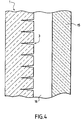
- FIG. 4 represents a part of a vertical section of a double insulating glazing in which the panel 1 according to the invention has been inserted.
- the double insulating glazing consists of transparent panel 1 according to the invention and a glass sheet 15, the panel 1 and the glass sheet 15 being separated from each other by an air knife 16 and united at their periphery through a profiled frame here not shown on the figure and known to those skilled in the art.
- the grooves 3 of the panel 1 are in contact with the air knife 16.
Landscapes
- Engineering & Computer Science (AREA)
- Architecture (AREA)
- Structural Engineering (AREA)
- General Engineering & Computer Science (AREA)
- Sustainable Development (AREA)
- Civil Engineering (AREA)
- Life Sciences & Earth Sciences (AREA)
- Securing Of Glass Panes Or The Like (AREA)
- Panels For Use In Building Construction (AREA)
- Laminated Bodies (AREA)
- Joining Of Glass To Other Materials (AREA)
- Finishing Walls (AREA)
- Devices Affording Protection Of Roads Or Walls For Sound Insulation (AREA)
Claims (9)
- Transparente Platte, die vorgesehen ist, insbesondere in die Fensteröffnung eines Gebäudes eingebaut zu werden, und es ermöglicht, die natürlich einfallenden Lichtstrahlen derart neu auszurichten, dass die Helligkeit in dem Gebäude vergleichmäßigt wird, welche mindestens eine Scheibe umfasst, die auf wenigstens einem Teil ihrer Dicke Rillen aufweist, die in Verwendungsposition horizontal und zueinander parallel angeordnet sind, dadurch gekennzeichnet, dass die Scheibe aus Glas besteht und die Rillen für das Auge unsichtbar und durch Erzeugung von Schlitzen mit einem Laser herausgeschnitten sind.
- Platte nach dem vorhergehenden Anspruch, dadurch gekennzeichnet, dass die Rillen im Wesentlichen senkrecht zur Ebene der Glasscheibe verlaufen.
- Platte nach einem dem vorhergehenden Ansprüche, dadurch gekennzeichnet, dass die Rillen gleichmäßig auf der Oberfläche der Glasscheibe verteilt sind.
- Platte nach einem dem vorhergehenden Ansprüche, dadurch gekennzeichnet, dass sie aus einem Verbund besteht, und dass die Tiefe der Rillen gleich der Dicke der Glasscheibe ist.
- Platte nach einem dem vorhergehenden Ansprüche, dadurch gekennzeichnet, dass sie aus einem Verbund besteht, der zwei Glasscheiben, wovon eine die Rillen enthält, und eine Zwischenfolie zwischen den zwei Glasscheiben umfasst.
- Platte nach Anspruch 4 oder 5, dadurch gekennzeichnet, dass die Zwischenfolie eine Polyvinylbutyralfolie ist, und dass eine die Rillen enthaltende Scheibe weniger dick als eine andere Scheibe ohne Rillen ist.
- Platte nach einem dem vorhergehenden Ansprüche, dadurch gekennzeichnet, dass das Verhältnis von Tiefe der Rillen zu Abstand zwischen zwei davon 0,5 bis 2 und vorzugsweise 1 bis 2 beträgt.
- Mehrscheiben-Isolierglas, das eine Luftfüllung enthält, dadurch gekennzeichnet, dass es eine Platte nach einem der vorhergehenden Ansprüche umfasst.
- Isolierglas nach dem vorhergehenden Anspruch, dadurch gekennzeichnet, dass die Fläche der die Rillen aufweisenden Platte sich mit der Luftfüllung in Berührung befindet.
Applications Claiming Priority (2)
| Application Number | Priority Date | Filing Date | Title |
|---|---|---|---|
| FR9807275 | 1998-06-10 | ||
| FR9807275A FR2779755B1 (fr) | 1998-06-10 | 1998-06-10 | Panneau transparent pour batiment ameliorant la luminosite naturelle a l'interieur du batiment |
Publications (2)
| Publication Number | Publication Date |
|---|---|
| EP0964112A1 EP0964112A1 (de) | 1999-12-15 |
| EP0964112B1 true EP0964112B1 (de) | 2004-01-21 |
Family
ID=9527212
Family Applications (1)
| Application Number | Title | Priority Date | Filing Date |
|---|---|---|---|
| EP99401403A Expired - Lifetime EP0964112B1 (de) | 1998-06-10 | 1999-06-10 | Lichtdurchlässiges Paneel für Gebäude, das die natürliche Helligkeit innerhalb des Gebäudes verbessert |
Country Status (6)
| Country | Link |
|---|---|
| EP (1) | EP0964112B1 (de) |
| AT (1) | ATE258257T1 (de) |
| DE (1) | DE69914256T2 (de) |
| ES (1) | ES2213990T3 (de) |
| FR (1) | FR2779755B1 (de) |
| PT (1) | PT964112E (de) |
Families Citing this family (1)
| Publication number | Priority date | Publication date | Assignee | Title |
|---|---|---|---|---|
| CN112659055A (zh) * | 2020-12-15 | 2021-04-16 | 南京凡芽智能设备有限公司 | 一种建筑玻璃幕墙制作加工方法 |
Family Cites Families (7)
| Publication number | Priority date | Publication date | Assignee | Title |
|---|---|---|---|---|
| IL65514A (en) * | 1982-04-18 | 1986-10-31 | Yitzchak Bar Yonah | Selectively light transmitting panel for buildings |
| NZ224424A (en) * | 1987-11-06 | 1990-12-21 | Ian Robert Edmonds | Light deflecting window panel: parallel cuts in transparent material by laser |
| JP3217385B2 (ja) * | 1991-02-21 | 2001-10-09 | 株式会社小坂研究所 | ガラスパネルの割断方法 |
| DE4134955A1 (de) * | 1991-10-23 | 1993-04-29 | Helmut Frank Ottomar P Mueller | Lichtleitvorrichtung |
| RU2024441C1 (ru) * | 1992-04-02 | 1994-12-15 | Владимир Степанович Кондратенко | Способ резки неметаллических материалов |
| DE4218215A1 (de) * | 1992-06-03 | 1993-12-09 | Ver Glaswerke Gmbh | Glasbaustein mit diffuser Lichtstreuung |
| US5880886A (en) * | 1993-05-04 | 1999-03-09 | Milner; Peter James | Optical component suitable for use in glazing |
-
1998
- 1998-06-10 FR FR9807275A patent/FR2779755B1/fr not_active Expired - Lifetime
-
1999
- 1999-06-10 ES ES99401403T patent/ES2213990T3/es not_active Expired - Lifetime
- 1999-06-10 PT PT99401403T patent/PT964112E/pt unknown
- 1999-06-10 AT AT99401403T patent/ATE258257T1/de active
- 1999-06-10 DE DE1999614256 patent/DE69914256T2/de not_active Expired - Lifetime
- 1999-06-10 EP EP99401403A patent/EP0964112B1/de not_active Expired - Lifetime
Also Published As
| Publication number | Publication date |
|---|---|
| ES2213990T3 (es) | 2004-09-01 |
| FR2779755A1 (fr) | 1999-12-17 |
| PT964112E (pt) | 2004-06-30 |
| DE69914256T2 (de) | 2004-11-18 |
| EP0964112A1 (de) | 1999-12-15 |
| ATE258257T1 (de) | 2004-02-15 |
| DE69914256D1 (de) | 2004-02-26 |
| FR2779755B1 (fr) | 2000-07-21 |
Similar Documents
| Publication | Publication Date | Title |
|---|---|---|
| EP3600884B1 (de) | Leuchtverglasung | |
| CA2266922C (fr) | Dispositif lumineux eclaire par la tranche | |
| EP2045515B1 (de) | Vorrichtung zur Beleuchtung oder Signalisierung für Kraftfahrzeuge | |
| CA2870104A1 (fr) | Vitrage eclairant avec deflecteur incorpore | |
| LU86377A1 (fr) | Vitrage transparent | |
| FR3034501A1 (fr) | Vitrage lumineux pour batiment, mobilier, vehicule de transport en commun | |
| FR2955915A1 (fr) | Vitrage multiple lumineux a diodes electroluminescentes | |
| FR2932307A1 (fr) | Dispositif d'affichage d'une image video sur un edifice | |
| FR2961609A1 (fr) | Dispositif a proprietes optiques et/ou energetiques electrocommandables | |
| GB2240576A (en) | Daylight-deflecting panel | |
| EP1654912A1 (de) | Leuchtelement mit mindestens einem substrat und einer lichtemittierenden beschichtung | |
| FR3069241B1 (fr) | Materiau comprenant un empilement a proprietes thermiques | |
| WO2023237839A1 (fr) | Vitrage lumineux feuilleté comprenant un revêtement fonctionnel | |
| EP0838628B1 (de) | Kraftfahrzeug- Scheinwerfer mit einem Lichtleiter | |
| EP2945917B1 (de) | Texturiertes glassubstrat für ein gebäude | |
| FR2964176A1 (fr) | Panneau decoratif et eclairant a diodes electroluminescentes | |
| WO2007057456A1 (fr) | Panneau émetteur de radiations lumineuses | |
| EP0964112A1 (de) | Lichtdurchlässiges Paneel für Gebäude, das die natürliche Helligkeit innerhalb des Gebäudes verbessert | |
| WO2012028813A1 (fr) | Vitrage multiple eclairant a diodes electroluminescentes | |
| FR2542063A1 (fr) | Dispositif d'eclairage anti-eblouissant | |
| EP0878661B1 (de) | Glaselement zur Raumbeleuchtung mit Tageslicht | |
| AU601634B2 (en) | A window panel for improved daylighting of room interiors | |
| WO2011070287A1 (fr) | Élément notamment pour façade comprenant une vitre et des diodes électroluminescentes | |
| WO2023247876A1 (fr) | Structure vitree eclairante | |
| EP0230854A1 (de) | Durchsichtige Platte als Teil eines Raumes in einem architektonischen Bau |
Legal Events
| Date | Code | Title | Description |
|---|---|---|---|
| PUAI | Public reference made under article 153(3) epc to a published international application that has entered the european phase |
Free format text: ORIGINAL CODE: 0009012 |
|
| AK | Designated contracting states |
Kind code of ref document: A1 Designated state(s): AT BE CH DE DK ES FI FR GB GR IE IT LI LU NL PT SE |
|
| AX | Request for extension of the european patent |
Free format text: AL;LT;LV;MK;RO;SI |
|
| 17P | Request for examination filed |
Effective date: 20000526 |
|
| AKX | Designation fees paid |
Free format text: AT BE CH DE DK ES FI LI |
|
| RBV | Designated contracting states (corrected) |
Designated state(s): AT BE CH DE DK ES FI FR GB GR IE IT LI LU NL PT SE |
|
| RAP1 | Party data changed (applicant data changed or rights of an application transferred) |
Owner name: SAINT-GOBAIN GLASS FRANCE |
|
| 17Q | First examination report despatched |
Effective date: 20020729 |
|
| GRAP | Despatch of communication of intention to grant a patent |
Free format text: ORIGINAL CODE: EPIDOSNIGR1 |
|
| GRAS | Grant fee paid |
Free format text: ORIGINAL CODE: EPIDOSNIGR3 |
|
| GRAA | (expected) grant |
Free format text: ORIGINAL CODE: 0009210 |
|
| AK | Designated contracting states |
Kind code of ref document: B1 Designated state(s): AT BE CH DE DK ES FI FR GB GR IE IT LI LU NL PT SE |
|
| PG25 | Lapsed in a contracting state [announced via postgrant information from national office to epo] |
Ref country code: IE Free format text: LAPSE BECAUSE OF FAILURE TO SUBMIT A TRANSLATION OF THE DESCRIPTION OR TO PAY THE FEE WITHIN THE PRESCRIBED TIME-LIMIT Effective date: 20040121 Ref country code: FI Free format text: LAPSE BECAUSE OF FAILURE TO SUBMIT A TRANSLATION OF THE DESCRIPTION OR TO PAY THE FEE WITHIN THE PRESCRIBED TIME-LIMIT Effective date: 20040121 |
|
| REG | Reference to a national code |
Ref country code: GB Ref legal event code: FG4D Free format text: NOT ENGLISH |
|
| REG | Reference to a national code |
Ref country code: CH Ref legal event code: EP |
|
| REG | Reference to a national code |
Ref country code: IE Ref legal event code: FG4D Free format text: FRENCH |
|
| REF | Corresponds to: |
Ref document number: 69914256 Country of ref document: DE Date of ref document: 20040226 Kind code of ref document: P |
|
| PG25 | Lapsed in a contracting state [announced via postgrant information from national office to epo] |
Ref country code: GR Free format text: LAPSE BECAUSE OF FAILURE TO SUBMIT A TRANSLATION OF THE DESCRIPTION OR TO PAY THE FEE WITHIN THE PRESCRIBED TIME-LIMIT Effective date: 20040421 Ref country code: DK Free format text: LAPSE BECAUSE OF FAILURE TO SUBMIT A TRANSLATION OF THE DESCRIPTION OR TO PAY THE FEE WITHIN THE PRESCRIBED TIME-LIMIT Effective date: 20040421 |
|
| REG | Reference to a national code |
Ref country code: SE Ref legal event code: TRGR |
|
| GBT | Gb: translation of ep patent filed (gb section 77(6)(a)/1977) |
Effective date: 20040423 |
|
| PG25 | Lapsed in a contracting state [announced via postgrant information from national office to epo] |
Ref country code: LI Free format text: LAPSE BECAUSE OF NON-PAYMENT OF DUE FEES Effective date: 20040630 Ref country code: CH Free format text: LAPSE BECAUSE OF NON-PAYMENT OF DUE FEES Effective date: 20040630 |
|
| REG | Reference to a national code |
Ref country code: PT Ref legal event code: SC4A Free format text: AVAILABILITY OF NATIONAL TRANSLATION Effective date: 20040414 |
|
| REG | Reference to a national code |
Ref country code: IE Ref legal event code: FD4D |
|
| REG | Reference to a national code |
Ref country code: ES Ref legal event code: FG2A Ref document number: 2213990 Country of ref document: ES Kind code of ref document: T3 |
|
| PLBE | No opposition filed within time limit |
Free format text: ORIGINAL CODE: 0009261 |
|
| STAA | Information on the status of an ep patent application or granted ep patent |
Free format text: STATUS: NO OPPOSITION FILED WITHIN TIME LIMIT |
|
| 26N | No opposition filed |
Effective date: 20041022 |
|
| REG | Reference to a national code |
Ref country code: CH Ref legal event code: PL |
|
| PG25 | Lapsed in a contracting state [announced via postgrant information from national office to epo] |
Ref country code: LU Free format text: LAPSE BECAUSE OF NON-PAYMENT OF DUE FEES Effective date: 20140610 |
|
| REG | Reference to a national code |
Ref country code: FR Ref legal event code: PLFP Year of fee payment: 18 |
|
| REG | Reference to a national code |
Ref country code: FR Ref legal event code: PLFP Year of fee payment: 19 |
|
| REG | Reference to a national code |
Ref country code: FR Ref legal event code: PLFP Year of fee payment: 20 |
|
| PGFP | Annual fee paid to national office [announced via postgrant information from national office to epo] |
Ref country code: NL Payment date: 20180613 Year of fee payment: 20 Ref country code: PT Payment date: 20180604 Year of fee payment: 20 Ref country code: DE Payment date: 20180530 Year of fee payment: 20 Ref country code: LU Payment date: 20180625 Year of fee payment: 20 |
|
| PGFP | Annual fee paid to national office [announced via postgrant information from national office to epo] |
Ref country code: AT Payment date: 20180525 Year of fee payment: 20 Ref country code: FR Payment date: 20180625 Year of fee payment: 20 Ref country code: BE Payment date: 20180626 Year of fee payment: 20 |
|
| PGFP | Annual fee paid to national office [announced via postgrant information from national office to epo] |
Ref country code: SE Payment date: 20180612 Year of fee payment: 20 |
|
| PGFP | Annual fee paid to national office [announced via postgrant information from national office to epo] |
Ref country code: GB Payment date: 20180606 Year of fee payment: 20 Ref country code: ES Payment date: 20180702 Year of fee payment: 20 Ref country code: IT Payment date: 20180625 Year of fee payment: 20 |
|
| REG | Reference to a national code |
Ref country code: DE Ref legal event code: R071 Ref document number: 69914256 Country of ref document: DE |
|
| REG | Reference to a national code |
Ref country code: NL Ref legal event code: MK Effective date: 20190609 |
|
| REG | Reference to a national code |
Ref country code: GB Ref legal event code: PE20 Expiry date: 20190609 Ref country code: BE Ref legal event code: MK Effective date: 20190610 |
|
| REG | Reference to a national code |
Ref country code: AT Ref legal event code: MK07 Ref document number: 258257 Country of ref document: AT Kind code of ref document: T Effective date: 20190610 |
|
| REG | Reference to a national code |
Ref country code: SE Ref legal event code: EUG |
|
| PG25 | Lapsed in a contracting state [announced via postgrant information from national office to epo] |
Ref country code: PT Free format text: LAPSE BECAUSE OF EXPIRATION OF PROTECTION Effective date: 20190621 |
|
| PG25 | Lapsed in a contracting state [announced via postgrant information from national office to epo] |
Ref country code: LU Free format text: LAPSE BECAUSE OF NON-PAYMENT OF DUE FEES Effective date: 20140610 Ref country code: GB Free format text: LAPSE BECAUSE OF EXPIRATION OF PROTECTION Effective date: 20190609 |
|
| PGRI | Patent reinstated in contracting state [announced from national office to epo] |
Ref country code: LU Effective date: 20150619 |
|
| REG | Reference to a national code |
Ref country code: ES Ref legal event code: FD2A Effective date: 20200903 |
|
| PG25 | Lapsed in a contracting state [announced via postgrant information from national office to epo] |
Ref country code: ES Free format text: LAPSE BECAUSE OF EXPIRATION OF PROTECTION Effective date: 20190611 |