EP0964188A2 - Faltenbalg - Google Patents
Faltenbalg Download PDFInfo
- Publication number
- EP0964188A2 EP0964188A2 EP99110843A EP99110843A EP0964188A2 EP 0964188 A2 EP0964188 A2 EP 0964188A2 EP 99110843 A EP99110843 A EP 99110843A EP 99110843 A EP99110843 A EP 99110843A EP 0964188 A2 EP0964188 A2 EP 0964188A2
- Authority
- EP
- European Patent Office
- Prior art keywords
- collar
- bellows according
- wall
- bellows
- radially
- Prior art date
- Legal status (The legal status is an assumption and is not a legal conclusion. Google has not performed a legal analysis and makes no representation as to the accuracy of the status listed.)
- Granted
Links
- 238000000071 blow moulding Methods 0.000 claims description 2
- 229920001169 thermoplastic Polymers 0.000 claims 1
- 230000015572 biosynthetic process Effects 0.000 description 1
- 238000011161 development Methods 0.000 description 1
- 230000018109 developmental process Effects 0.000 description 1
- 230000000694 effects Effects 0.000 description 1
- 238000007373 indentation Methods 0.000 description 1
- 230000036316 preload Effects 0.000 description 1
- 238000007789 sealing Methods 0.000 description 1
- 238000007493 shaping process Methods 0.000 description 1
- 239000012815 thermoplastic material Substances 0.000 description 1
Images

Classifications
-
- F—MECHANICAL ENGINEERING; LIGHTING; HEATING; WEAPONS; BLASTING
- F16—ENGINEERING ELEMENTS AND UNITS; GENERAL MEASURES FOR PRODUCING AND MAINTAINING EFFECTIVE FUNCTIONING OF MACHINES OR INSTALLATIONS; THERMAL INSULATION IN GENERAL
- F16J—PISTONS; CYLINDERS; SEALINGS
- F16J3/00—Diaphragms; Bellows; Bellows pistons
- F16J3/04—Bellows
- F16J3/041—Non-metallic bellows
- F16J3/042—Fastening details
Definitions
- the invention relates to a by blow molding a tubular blank bellows formed thermoplastic material according to the preamble of Claim 1.
- the present invention has for its object to provide a bellows whose fastening collar only secure internal fastening in a connecting piece through constructive design without any additional effort.
- the radial depth advantageously greater - and preferably at least twice as large - as their axial width.
- the radial one Depth of the ring grooves is expediently at least equal to the wall thickness of the Fastening collar.
- a circumferential ring groove on the free end of the fastening collar facing side of the locking lug immediately next to this is designed so that that of its side walls, which runs away from the free fret end, with the free wall end facing side wall of the latch coincides; i.e. this Sidewall is a common part of the latch and said ring groove. Further is it is advantageous to the fastening collar between this ring groove and the free end of the collar cone-shaped - that is, tapering - so that he can insert the Fastening collar in the recess of the associated fastening piece according to Art a delay ramp relieved.
- Another circumferential annular groove is at the free end of the fastening collar opposite side of the locking lug advantageously arranged so that - starting from Foot area of the locking lug, up to which the radial is in the assembled state of the bellows inwardly projecting locking edge of the connecting piece extends - radially in the direction of Bellows axis is molded.
- the outer contour of the fastening collar preferably corresponds to said one Foot area of the locking lug of the inner contour of the locking lug here in the assembled state of the Bellows engaging catch edge of the connecting piece, so that a positive Parenthesis results. It is also expedient to adjust the outer diameter of the locking lug slightly larger than the clear width of the recess of the associated connection piece form, so that the locking lug during assembly under radial preload behind the Locking edge of the connecting piece comes to rest on the inner wall.
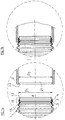
- FIGS. 1a and 1b show the end region of a bellows according to the invention together with an associated connection piece separately or in the assembled state
- FIG. 2 shows the same fastening collar
- FIG. 3 shows a modified embodiment on an enlarged scale.
- FIG. 1a shows at least one axial end of an inventive Bellows 1 with a fastening collar 1.1, which extends from the free end 1.2 in Direction of the first fold 1.5 of the fold area of the bellows and extends into one Corresponding recess 2.1 of a connecting piece 2 can be inserted and in this is fixable.
- This waist band has a circumferential locking lug 3 which is known per se on, the radial formation of the bellows wall directed from the inside to the outside is generated and in the axial longitudinal section approximately U-shaped with approximately radially aligned Legs is formed.
- one circumferential annular groove is formed approximately radially from the outside inwards into the flange wall, and on the side of the locking lug facing the free end 1.2 of the fastening collar 3 so that the relevant end wall 3.1 of the locking lug 3 as a whole with the one facing it Wall 4.1 of the annular groove 4 coincides and that on the other side of the latch 3 there circumferential annular groove 5 is arranged so that it is only below the foot area 3.2 of the locking lug 3 extends approximately radially from the outside inwards.
- the end of the collar 1.2 is a radially tapering cone-shaped ramp 1.4 shaped so that it slides easily over the locking edge 2.2 in the cylindrical Can insert recess 2.1 of the associated connector 2.
- the fastening collar is then pushed so far into the recess 2.1 that the locking edge 2.2 Engages behind locking lug 3 and up to the foot area 3.2 (see FIG. 2) above the annular groove 5 - preferably positively - engages, as shown in Figure 1b.
- Another ring groove 6 can, for example, be provided after the annular groove 5 (FIG. 3).
- FIG. 1a Another advantageous embodiment of the present invention is that the outer diameter D 1 of the locking lug 3 before the bellows is assembled (FIG. 1a) is slightly larger than the slight width D 2 of the recess 2.1 of the connecting piece 2. This has the consequence that the latch 3 after assembly (Fig. 1b) engages under tension in the recess 2.1 of the connecting piece 2, whereby the fixation of the latch 3 is strengthened and its sealing effect is improved.
Landscapes
- Engineering & Computer Science (AREA)
- General Engineering & Computer Science (AREA)
- Mechanical Engineering (AREA)
- Diaphragms And Bellows (AREA)
Abstract
Description
Claims (9)
- Durch Blasformung eines schlauchförmigen Rohlings aus thermoplastischem Kunststoff gebildeter Faltenbalg (1), der an mindestens einem seiner axialen Enden einen in eine zylindrische Ausnehmung (2.1) eines Anschlußstutzens (2) fromschlüssig einsteckbaren und in dieser von innen her verrastbaren Befestigungsbund (1.1) aufweist, wobei an den Befestigungsbund (1.1) mindestens eine radial nach außen gerichtete Rastnase (3) angeformt ist, die mit einer an der Innenwand der Ausnehmung (2.1) angeordneten radial nach innen vorspringenden Rastkante (2.2) zusammenwirkt,
dadurch gekennzeichnet,
daß die Rastnase (3) als umlaufende, radial nach außen gerichtete, im axialen Längsschnitt etwa U-förmige Ausformung der Bundwandung (1.3) mit annähernd radial verlaufenden Seitenwänden gebildet ist und daß zu ihr parallel, unmittelbar benachbart mindestens eine umlaufende etwa radial von außen nach innen in die Bundwandung (1.3) eingeformte, axial schmale Ringnut (4, 5, 6) angeordnet ist. - Faltenbalg nach Anspruch 1, dadurch gekennzeichnet, daß die radiale Tiefe (T) der Ringnut(en) (4, 5, 6) größer als ihre axiale Breite (B) ist.
- Faltenbalg nach Anspruch 2, dadurch gekennzeichnet, daß die radiale Tiefe (T) der Ringnut(en) (4, 5, 6) mindestens doppelt so groß wie ihre axiale Breite (B) ist.
- Faltenbalg nach einem der Ansprüche 1 bis 3, dadurch gekennzeichnet, daß die radiale Tiefe (T) der Ringnut(en) (4, 5, 6) mindestens gleich der Wandstärke (W) der Bundwandung (1.3) ist.
- Faltenbalg nach einem der Ansprüche 1 bis 4, dadurch gekennzeichnet, daß an der dem freien Ende (1.2) des Befestigungsbundes (1.1) zugewandten Seite der Rastnase (3) eine umlaufende Ringnut (4) so angeordnet ist, daß ihre dem freien Bundende (1.2) abgewandte Seitenwand (4.1) mit der dem freien Bundende (1.2) zugewandten Seitenwand (3.1) der Rastnase (3) zusammenfällt.
- Faltenbalg nach einem der Ansprüche 1 bis 5, dadurch gekennzeichnet, daß sich der Befestigungsbund (1.1) zwischen der umlaufenden Ringnut (4) und dem freien Bundende (1.2) - eine kegelmantelförmige Aufschubrampe (1.4) bildend - radial verjüngt.
- Faltenbalg nach einem der Ansprüche 1 bis 6, dadurch gekennzeichnet, daß an der dem freien Ende (1.2) des Befestigungsbundes (1.1) abgewandten Seite der Rastnase (3) eine umlaufende Ringnut (5) so angeordnet ist, daß sie sich vom Fußbereich (3.2) der Rastnase (3) radial nach innen erstreckt.
- Faltenbalg nach einem der Ansprüche 1 bis 7, dadurch gekennzeichnet, daß die Außenkontur des Befestigungsbundes (1.1) am Fußbereich (3.2) der Rastnase (3) der Innenkontur der Rastkante (2.2) des Anschlußstutzens (2) entspricht.
- Faltenbalg nach einem der Ansprüche 1 bis 8, dadurch gekennzeichnet, daß der Außendurchmesser (D1) der Rastnase (3) geringfügig größer ist als die lichte Weite (D2) der Ausnehmung (2.1) des Anschlußstutzens (2).
Applications Claiming Priority (2)
| Application Number | Priority Date | Filing Date | Title |
|---|---|---|---|
| DE19826344 | 1998-06-12 | ||
| DE19826344A DE19826344C1 (de) | 1998-06-12 | 1998-06-12 | Faltenbalg |
Publications (3)
| Publication Number | Publication Date |
|---|---|
| EP0964188A2 true EP0964188A2 (de) | 1999-12-15 |
| EP0964188A3 EP0964188A3 (de) | 2000-10-25 |
| EP0964188B1 EP0964188B1 (de) | 2004-09-08 |
Family
ID=7870762
Family Applications (1)
| Application Number | Title | Priority Date | Filing Date |
|---|---|---|---|
| EP99110843A Expired - Lifetime EP0964188B1 (de) | 1998-06-12 | 1999-06-07 | Faltenbalg |
Country Status (3)
| Country | Link |
|---|---|
| EP (1) | EP0964188B1 (de) |
| DE (2) | DE19826344C1 (de) |
| ES (1) | ES2229582T3 (de) |
Citations (2)
| Publication number | Priority date | Publication date | Assignee | Title |
|---|---|---|---|---|
| EP0375873A2 (de) | 1988-12-27 | 1990-07-04 | Continental Aktiengesellschaft | Innenbefestigung von Faltenbälgen |
| EP0299850B1 (de) | 1987-07-06 | 1991-05-29 | Automobiles Peugeot | Balgdichtung |
Family Cites Families (4)
| Publication number | Priority date | Publication date | Assignee | Title |
|---|---|---|---|---|
| FR2165022A7 (de) * | 1971-12-13 | 1973-08-03 | Pont A Mousson | |
| IT1207810B (it) * | 1987-06-12 | 1989-06-01 | Trw Italia Spa | Cuffia di protezione a soffietto particolarmente per meccanismi sterzanti di autoveicoli. |
| GB2287071A (en) * | 1994-02-24 | 1995-09-06 | Draftex Ind Ltd | Attachment of protective bellows |
| GB2287074A (en) * | 1994-02-24 | 1995-09-06 | Draftex Ind Ltd | End fixing of protective bellows |
-
1998
- 1998-06-12 DE DE19826344A patent/DE19826344C1/de not_active Expired - Fee Related
-
1999
- 1999-06-07 ES ES99110843T patent/ES2229582T3/es not_active Expired - Lifetime
- 1999-06-07 DE DE59910428T patent/DE59910428D1/de not_active Expired - Lifetime
- 1999-06-07 EP EP99110843A patent/EP0964188B1/de not_active Expired - Lifetime
Patent Citations (2)
| Publication number | Priority date | Publication date | Assignee | Title |
|---|---|---|---|---|
| EP0299850B1 (de) | 1987-07-06 | 1991-05-29 | Automobiles Peugeot | Balgdichtung |
| EP0375873A2 (de) | 1988-12-27 | 1990-07-04 | Continental Aktiengesellschaft | Innenbefestigung von Faltenbälgen |
Also Published As
| Publication number | Publication date |
|---|---|
| EP0964188B1 (de) | 2004-09-08 |
| DE19826344C1 (de) | 1999-08-26 |
| DE59910428D1 (de) | 2004-10-14 |
| ES2229582T3 (es) | 2005-04-16 |
| EP0964188A3 (de) | 2000-10-25 |
Similar Documents
| Publication | Publication Date | Title |
|---|---|---|
| DE69417441T2 (de) | Vorrichtung zum herstellen von verbindungen | |
| DE69415534T2 (de) | Wiederverwendbares siegel für einen stab | |
| EP2304303B1 (de) | Pressfitting für ein rohr, insbesondere kunststoffrohr oder kunststoff-metall-verbundrohr | |
| EP0465896A1 (de) | Verbindungselement für Wellrohre und Schläuche | |
| DE19804719C1 (de) | Anschlußarmatur mit axial vorstehendem Befestigungsvorsprung | |
| DE3925245A1 (de) | Flexible, kuppelbare, mit einer faltung versehene leitung | |
| EP1152497A2 (de) | Rundsteckverbinder | |
| DE69401652T2 (de) | Schnellkupplung für rohre oder schläuche | |
| DE2906317A1 (de) | Rohrverbindungsteil und mit diesem hergestellte rohrverbindung | |
| DE69704909T2 (de) | Zwischenstück zum Reflektoreinbau auf ein Auflagelement eines Scheinwerfers | |
| DE4403584A1 (de) | Kugelzapfen eines Kugelgelenks für Kraftfahrzeuge | |
| DE8629478U1 (de) | Kabelschloß | |
| EP0549860A1 (de) | Vorrichtung zum gegenseitigen Verbinden von zwei Leitungen, insbesondere Kraftstoffleitungen | |
| EP0631081B1 (de) | Anschlussvorrichtung für Rohrleitungen mit geschlitztem Klemmring | |
| DE3345903C2 (de) | ||
| DE20206730U1 (de) | Kupplungsmuffe für die Verbindung eines Saugschlauchs mit einem Gehäuse | |
| EP0964188B1 (de) | Faltenbalg | |
| EP0004067B1 (de) | Wickelträger mit parallel zu seiner Achse verlaufenden Tragelementen | |
| DE19630225A1 (de) | Rohrsystem, insbesondere zur Anwendung in einer Gerüstkonstruktion, sowie Rohre für ein Rohrsystem | |
| EP3434953B1 (de) | Sicherungsring, abgasrohrsystem mit sicherungsring | |
| DE8205016U1 (de) | Kupplung fuer druckleitungen | |
| DE102007036349A1 (de) | Montageeinheit, Befestigereinheit und Verfahren zur Herstellung einer Montageeinheit | |
| DE3426579C2 (de) | ||
| EP0458126A2 (de) | Selbstsichernder Sperrbolzen | |
| EP2982893B1 (de) | Rohrklemmanordnung |
Legal Events
| Date | Code | Title | Description |
|---|---|---|---|
| PUAI | Public reference made under article 153(3) epc to a published international application that has entered the european phase |
Free format text: ORIGINAL CODE: 0009012 |
|
| AK | Designated contracting states |
Kind code of ref document: A2 Designated state(s): DE ES FR IT |
|
| AX | Request for extension of the european patent |
Free format text: AL;LT;LV;MK;RO;SI |
|
| PUAL | Search report despatched |
Free format text: ORIGINAL CODE: 0009013 |
|
| AK | Designated contracting states |
Kind code of ref document: A3 Designated state(s): AT BE CH CY DE DK ES FI FR GB GR IE IT LI LU MC NL PT SE |
|
| AX | Request for extension of the european patent |
Free format text: AL;LT;LV;MK;RO;SI |
|
| 17P | Request for examination filed |
Effective date: 20010425 |
|
| AKX | Designation fees paid |
Free format text: DE ES FR IT |
|
| GRAP | Despatch of communication of intention to grant a patent |
Free format text: ORIGINAL CODE: EPIDOSNIGR1 |
|
| GRAS | Grant fee paid |
Free format text: ORIGINAL CODE: EPIDOSNIGR3 |
|
| GRAA | (expected) grant |
Free format text: ORIGINAL CODE: 0009210 |
|
| AK | Designated contracting states |
Kind code of ref document: B1 Designated state(s): DE ES FR IT |
|
| REF | Corresponds to: |
Ref document number: 59910428 Country of ref document: DE Date of ref document: 20041014 Kind code of ref document: P |
|
| REG | Reference to a national code |
Ref country code: ES Ref legal event code: FG2A Ref document number: 2229582 Country of ref document: ES Kind code of ref document: T3 |
|
| ET | Fr: translation filed | ||
| PLBE | No opposition filed within time limit |
Free format text: ORIGINAL CODE: 0009261 |
|
| STAA | Information on the status of an ep patent application or granted ep patent |
Free format text: STATUS: NO OPPOSITION FILED WITHIN TIME LIMIT |
|
| 26N | No opposition filed |
Effective date: 20050609 |
|
| PGFP | Annual fee paid to national office [announced via postgrant information from national office to epo] |
Ref country code: ES Payment date: 20090623 Year of fee payment: 11 |
|
| PGFP | Annual fee paid to national office [announced via postgrant information from national office to epo] |
Ref country code: IT Payment date: 20090624 Year of fee payment: 11 Ref country code: FR Payment date: 20090615 Year of fee payment: 11 |
|
| REG | Reference to a national code |
Ref country code: FR Ref legal event code: ST Effective date: 20110228 |
|
| PG25 | Lapsed in a contracting state [announced via postgrant information from national office to epo] |
Ref country code: IT Free format text: LAPSE BECAUSE OF NON-PAYMENT OF DUE FEES Effective date: 20100607 |
|
| PG25 | Lapsed in a contracting state [announced via postgrant information from national office to epo] |
Ref country code: FR Free format text: LAPSE BECAUSE OF NON-PAYMENT OF DUE FEES Effective date: 20100630 |
|
| REG | Reference to a national code |
Ref country code: ES Ref legal event code: FD2A Effective date: 20110715 |
|
| PG25 | Lapsed in a contracting state [announced via postgrant information from national office to epo] |
Ref country code: ES Free format text: LAPSE BECAUSE OF NON-PAYMENT OF DUE FEES Effective date: 20110705 |
|
| PG25 | Lapsed in a contracting state [announced via postgrant information from national office to epo] |
Ref country code: ES Free format text: LAPSE BECAUSE OF NON-PAYMENT OF DUE FEES Effective date: 20100608 |
|
| PGFP | Annual fee paid to national office [announced via postgrant information from national office to epo] |
Ref country code: DE Payment date: 20180630 Year of fee payment: 20 |
|
| REG | Reference to a national code |
Ref country code: DE Ref legal event code: R071 Ref document number: 59910428 Country of ref document: DE |