EP0964203A1 - Gas burner - Google Patents
Gas burner Download PDFInfo
- Publication number
- EP0964203A1 EP0964203A1 EP98830358A EP98830358A EP0964203A1 EP 0964203 A1 EP0964203 A1 EP 0964203A1 EP 98830358 A EP98830358 A EP 98830358A EP 98830358 A EP98830358 A EP 98830358A EP 0964203 A1 EP0964203 A1 EP 0964203A1
- Authority
- EP
- European Patent Office
- Prior art keywords
- burner
- plate
- burner according
- hole
- elastic
- Prior art date
- Legal status (The legal status is an assumption and is not a legal conclusion. Google has not performed a legal analysis and makes no representation as to the accuracy of the status listed.)
- Withdrawn
Links
- 239000000463 material Substances 0.000 claims description 13
- 239000002196 Pyroceram Substances 0.000 claims description 10
- 238000010411 cooking Methods 0.000 description 9
- 239000000919 ceramic Substances 0.000 description 2
- 238000006073 displacement reaction Methods 0.000 description 2
- 239000011521 glass Substances 0.000 description 2
- 230000000452 restraining effect Effects 0.000 description 2
- 238000001816 cooling Methods 0.000 description 1
- 239000003292 glue Substances 0.000 description 1
- 238000010438 heat treatment Methods 0.000 description 1
- 238000009434 installation Methods 0.000 description 1
- 239000007788 liquid Substances 0.000 description 1
- 238000012423 maintenance Methods 0.000 description 1
- 239000002184 metal Substances 0.000 description 1
- 239000007769 metal material Substances 0.000 description 1
- 238000000034 method Methods 0.000 description 1
- 239000002245 particle Substances 0.000 description 1
- 230000035515 penetration Effects 0.000 description 1
- 230000001105 regulatory effect Effects 0.000 description 1
- 239000002210 silicon-based material Substances 0.000 description 1
Images

Classifications
-
- F—MECHANICAL ENGINEERING; LIGHTING; HEATING; WEAPONS; BLASTING
- F23—COMBUSTION APPARATUS; COMBUSTION PROCESSES
- F23D—BURNERS
- F23D14/00—Burners for combustion of a gas, e.g. of a gas stored under pressure as a liquid
- F23D14/02—Premix gas burners, i.e. in which gaseous fuel is mixed with combustion air upstream of the combustion zone
- F23D14/04—Premix gas burners, i.e. in which gaseous fuel is mixed with combustion air upstream of the combustion zone induction type, e.g. Bunsen burner
- F23D14/06—Premix gas burners, i.e. in which gaseous fuel is mixed with combustion air upstream of the combustion zone induction type, e.g. Bunsen burner with radial outlets at the burner head
-
- F—MECHANICAL ENGINEERING; LIGHTING; HEATING; WEAPONS; BLASTING
- F24—HEATING; RANGES; VENTILATING
- F24C—DOMESTIC STOVES OR RANGES ; DETAILS OF DOMESTIC STOVES OR RANGES, OF GENERAL APPLICATION
- F24C3/00—Stoves or ranges for gaseous fuels
- F24C3/08—Arrangement or mounting of burners
- F24C3/085—Arrangement or mounting of burners on ranges
Definitions
- the present invention refers to gas burners for domestic appliances, particularly susceptible to use in hobs provided with plates made of pyroceram or other brittle material having holes in correspondence with the burners.
- the use of gas burners with such cooking plates requires holes in the cooking plate suitable for housing the burners, in such a way that the feeder heads of the burners remain in a raised position above the plate.
- hobs a serious drawback of joining materials such as pyroceram and metal materials in hobs is the mutual interference which is generated between the plate and the burners due to their different coefficients of thermal expansion and different heating/cooling times. In a normal thermal cycle in the use of the burner, this could cause great internal stress in the brittle material were there not a certain gap between the burner and the plate and were the burner not free to move with respect to the plate. Therefore, in order to solve this problem, which can lead to frequent breakage of the brittle material, and to make the hob safe even should the plate break, recent embodiments of hobs comprise a box-type frame beneath the pyroceram plate, provided with support elements for the burners in correspondence with the holes obtained in said plate.
- the gas burners are mounted using elastic means on the support elements of the frame so that they can slide along their axis, while the holes in the plate are suitable outsized with respect to the size of each burner, to allow reduced transversal movement of the latter. Moreover, there are matching elements on the side walls of each burner which fit into the lower surface of the plate in order to keep each burner in position, opposing the upward thrust exerted by the elastic means.
- the European patent application No. 0.727.619 in the name of SCHOTT GLASWERKE provides the use of flat springs on the lower wall of the box-type frame in order to support the gas burners in correspondence with the holes in the upper plate made of pyroceram.
- the United States patent No. 5.313.929 in the name of SCHOTT GLASWERKE, illustrates, for example, the use in cooking plates made of brittle materials of a first seal interposed between the burner and the upper surface of the plate and a second seal interposed between a support integral with the burner and the lower surface of the same plate.
- a further drawback of the above embodiments is that the seal cannot be easily fitted between the burner and the edge of the hole in the plate so as to ensure that the seal is completely tight since the force exerted by the elastic means makes this operation difficult.
- a scope of the present invention is to solve the above mentioned problems by supplying a gas burner suitable for use in hobs with a plate made of brittle material such as pyroceram with holes obtained in it, which is easy to install and does not require that the plate be fixed in place.
- a further scope of the present invention is to supply a gas burner which allows for the easy fitting in an optimal position of a tight seal between the edge of each hole in the plate and the respective burner.
- the gas burner according to the invention is particularly suitable for use in hobs with an upper plate made of brittle material with at least one hole for housing the burner, and comprises a burner body and a removable feeder head.
- the burner body is supported at the hole by elastic fixing means and moreover has means for centering it with respect to the plate. These centering means allow the burner to move along its axis with respect to the plate, but prevent it from rotating with respect to said axis.
- the elastic fixing means comprise an elastic element set against an opposing flange which define a housing suited to elastically restrain the edge of the hole in the plate made of brittle material.
- the centering means may be connected to a box-type frame placed beneath the plate and comprise at least one pivot integral with the body of the burner and suited to fitting into the corresponding hole in said frame, in such a way that the burner is free to slide along its axis.
- the elastic fixing means are connected to the body of the burner by means of registrable means of restraint.
- said means of restraint comprise a threaded screw and a bracket integral with the body of the burner.
- the burner which as a whole is marked 15, according to a preferred embodiment of the present invention, is mounted on a cooking plate 1 made of pyroceram or other brittle material, in correspondence with a hole obtained in said plate 1 in order to house it.
- a box-type frame 2 Beneath the plate 1 there is a box-type frame 2 which, in traditional embodiments, serves to support the burners.
- the burner 15 is moreover surrounded by a support grill 14 for domestic cooking utensils.
- the burner 15 is also provided, see figure 2, with a spark plug 12 and a thermocouple 13. As illustrated in figures 2, 3 and 4, the burner 15 comprises a body of the burner 4 and a removable feeder head 3 fitted to the body of the burner 4.
- brackets 7a and 7b On the upper surface of the body of the burner 4 there are two brackets 7a and 7b which are cut into the body 4 and are diametrically opposed, each with a threaded hole to house two corresponding restraining screws 8a and 8b. Between each bracket 7a and 7b and each corresponding screw 8a and 8b, there is a circular flange 6 and a Belleville washer 5 which surround the body of said burner 4 and have holes for the screws 8a and 8b to fit into.
- the Belleville washer 5 and the circular flange 6 define together a housing suited to restraining the free edge of the hole in the plate 1. In particular, the Belleville washer 5 exerts an opposing action with respect to the circular flange 6 which determines the elastic fixing of the body of the burner 4 on the plate 1.
- the distance between the washer 5 and the flange 6 may be regulated by means of the screws 7a and 7b, as a function of the thickness of the plate 1 and the conformation of the washer 5 and the flange 6.
- the body of the burner 4 comprises moreover a seal 11, preferably made of silicon material, interposed between the Belleville washer 5 and the flange 6.
- the action of the washer 5 on the seal 11 is such as to keep said seal 11 in constant contact with the plate 1 so as to ensure an optimum seal even in the case of transversal or axial displacement of the body 4.
- the Belleville washer 5 and the circular flange 6 have circular holes to house the spark plug 12 and the thermocouple 13.
- the screws 9a and 9b are also filled into two corresponding openings to be found on a projecting part 10 of the bottom of the box-type frame 2.
- the screws 9a and 9b serve principally to centre the body of the burner 4 on the frame 2, and therefore with respect to the plate 1, preventing the body of the burner 4 from rotating on its axis.
- the distance between the heads of the screws 9a and 9b and the bottom wall of the body of the burner 4 defines moreover the maximum axial displacement possible of said body of the burner 4.
- the burner 15 is able to move axially and to a limited extent transversally, with respect to the pyroceram plate 1, while still keeping the seal 11 interposed between the body of the burner 4 and the edge of the hole in said plate 1, thus ensuring an optimum seal.
- the installation of the burner 15 on the plate 1 is facilitated by the fact that there are no forces exerting an upward thrust on the plate 1, but only relative forces between the plate 1 and the burner 15. This makes it possible to simply position the cooking plate 1 on supports without any need for fixing said plate 1 definitively to a housing.
- the mounting of the burner 15 is not hampered by the elastic elements.
Landscapes
- Engineering & Computer Science (AREA)
- Chemical & Material Sciences (AREA)
- Combustion & Propulsion (AREA)
- Mechanical Engineering (AREA)
- General Engineering & Computer Science (AREA)
- Gas Burners (AREA)
Abstract
A gas burner (15) for domestic appliances of the type comprising a
body (4) of the burner and a feeder head (3) for use in hobs with a top
plate (1) with at least one hole for housing said burner. The body of
the burner is supported elastically by elastic fixing means (5,6) at the
edge of said hole and comprises means (9a,9b) for centering it with
respect to the plate. These centering means allow for axial movement of
the body of the burner with respect to the plate.
Description
- The present invention refers to gas burners for domestic appliances, particularly susceptible to use in hobs provided with plates made of pyroceram or other brittle material having holes in correspondence with the burners.
- There is increasingly widespread use of ceramic or glass material, and especially pyroceram, in cooking plates for domestic cookers due to the ease of maintenance as well as to aesthetic reasons.
- According to a known technique, the use of gas burners with such cooking plates requires holes in the cooking plate suitable for housing the burners, in such a way that the feeder heads of the burners remain in a raised position above the plate.
- However, when cooking plates made of brittle material such as ceramic, glass or pyroceram are joined with traditional gas burners, generally made of metal, certain measures must be taken in order to avoid dangerous breakage of the plate itself.
- In fact, a serious drawback of joining materials such as pyroceram and metal materials in hobs is the mutual interference which is generated between the plate and the burners due to their different coefficients of thermal expansion and different heating/cooling times. In a normal thermal cycle in the use of the burner, this could cause great internal stress in the brittle material were there not a certain gap between the burner and the plate and were the burner not free to move with respect to the plate. Therefore, in order to solve this problem, which can lead to frequent breakage of the brittle material, and to make the hob safe even should the plate break, recent embodiments of hobs comprise a box-type frame beneath the pyroceram plate, provided with support elements for the burners in correspondence with the holes obtained in said plate. The gas burners are mounted using elastic means on the support elements of the frame so that they can slide along their axis, while the holes in the plate are suitable outsized with respect to the size of each burner, to allow reduced transversal movement of the latter. Moreover, there are matching elements on the side walls of each burner which fit into the lower surface of the plate in order to keep each burner in position, opposing the upward thrust exerted by the elastic means.
- The European patent application No. 0.727.619 in the name of SCHOTT GLASWERKE, for example, provides the use of flat springs on the lower wall of the box-type frame in order to support the gas burners in correspondence with the holes in the upper plate made of pyroceram.
- In order to avoid the penetration of liquids or extraneous particles between the burners and the plate and their deposit inside the box-type frame, it is also known to interpose a tight seal, that may be elastically strained, between the edge of each hole in the plate and the body of the burner housed in it, or, in any case, between the burner and the plate.
- The United States patent No. 5.313.929, in the name of SCHOTT GLASWERKE, illustrates, for example, the use in cooking plates made of brittle materials of a first seal interposed between the burner and the upper surface of the plate and a second seal interposed between a support integral with the burner and the lower surface of the same plate.
- These embodiments however, present the drawback of not being easy to assemble, since the interposition of thrusting elastic means between the bottom frame and the cooking plate makes it difficult to insert the burners into the respective holes.
- Moreover, it is necessary to fix the plate, for example using silicone-base glues, to a supporting housing, so as to prevent the action of the elastic means on the burners and that of the burners on the plate by means of the above mentioned matching elements, pushing the plate upwards and out of its housing.
- A further drawback of the above embodiments is that the seal cannot be easily fitted between the burner and the edge of the hole in the plate so as to ensure that the seal is completely tight since the force exerted by the elastic means makes this operation difficult.
- A scope of the present invention is to solve the above mentioned problems by supplying a gas burner suitable for use in hobs with a plate made of brittle material such as pyroceram with holes obtained in it, which is easy to install and does not require that the plate be fixed in place.
- A further scope of the present invention is to supply a gas burner which allows for the easy fitting in an optimal position of a tight seal between the edge of each hole in the plate and the respective burner.
- These scopes are achieved by the gas burner for domestic appliances suitable for use in hobs with an upper plate with at least one hole for housing the burner and a lower box-type frame, as claimed in the main claim.
- The gas burner according to the invention is particularly suitable for use in hobs with an upper plate made of brittle material with at least one hole for housing the burner, and comprises a burner body and a removable feeder head. The burner body is supported at the hole by elastic fixing means and moreover has means for centering it with respect to the plate. These centering means allow the burner to move along its axis with respect to the plate, but prevent it from rotating with respect to said axis.
- According to a peculiar aspect of the present invention, the elastic fixing means comprise an elastic element set against an opposing flange which define a housing suited to elastically restrain the edge of the hole in the plate made of brittle material.
- According to another aspect of the present invention, the centering means may be connected to a box-type frame placed beneath the plate and comprise at least one pivot integral with the body of the burner and suited to fitting into the corresponding hole in said frame, in such a way that the burner is free to slide along its axis.
- In a particular embodiment of the present invention, the elastic fixing means are connected to the body of the burner by means of registrable means of restraint.
- According to a preferred embodiment of the present invention, said means of restraint comprise a threaded screw and a bracket integral with the body of the burner.
- A preferred embodiment of the invention will be shown in the appended figures, in order to illustrate the invention but not intended to be limitative thereof, wherein:
- figure 1 is a side view of a gas burner used in a hob with a plate made of brittle material, according to the invention;
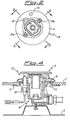
- figure 2 is a top view of the body of the burner in figure 1;
- figure 3 is an A-A section view of figure 2 of the burner according to the invention; and
- figure 4 is a B-B section view of figure 2 of the same burner.
-
- With reference to figures 1 and 3, the burner, which as a whole is marked 15, according to a preferred embodiment of the present invention, is mounted on a
cooking plate 1 made of pyroceram or other brittle material, in correspondence with a hole obtained in saidplate 1 in order to house it. Beneath theplate 1 there is a box-type frame 2 which, in traditional embodiments, serves to support the burners. Theburner 15 is moreover surrounded by asupport grill 14 for domestic cooking utensils. - The
burner 15 is also provided, see figure 2, with aspark plug 12 and athermocouple 13. As illustrated in figures 2, 3 and 4, theburner 15 comprises a body of theburner 4 and a removable feeder head 3 fitted to the body of theburner 4. - On the upper surface of the body of the
burner 4 there are twobrackets 7a and 7b which are cut into thebody 4 and are diametrically opposed, each with a threaded hole to house twocorresponding restraining screws bracket 7a and 7b and eachcorresponding screw circular flange 6 and a Bellevillewasher 5 which surround the body of saidburner 4 and have holes for thescrews circular flange 6 define together a housing suited to restraining the free edge of the hole in theplate 1. In particular, the Bellevillewasher 5 exerts an opposing action with respect to thecircular flange 6 which determines the elastic fixing of the body of theburner 4 on theplate 1. - The distance between the
washer 5 and theflange 6 may be regulated by means of thescrews 7a and 7b, as a function of the thickness of theplate 1 and the conformation of thewasher 5 and theflange 6. - The body of the
burner 4 comprises moreover aseal 11, preferably made of silicon material, interposed between the Bellevillewasher 5 and theflange 6. The action of thewasher 5 on theseal 11 is such as to keep saidseal 11 in constant contact with theplate 1 so as to ensure an optimum seal even in the case of transversal or axial displacement of thebody 4. - With particular reference to figures 2 and 4, the Belleville washer 5 and the
circular flange 6 have circular holes to house thespark plug 12 and thethermocouple 13. At the bottom wall of the body of theburner 4, there are twointernal threads screws 9a and 9b. Thescrews 9a and 9b are also filled into two corresponding openings to be found on a projectingpart 10 of the bottom of the box-type frame 2. - The
screws 9a and 9b serve principally to centre the body of theburner 4 on theframe 2, and therefore with respect to theplate 1, preventing the body of theburner 4 from rotating on its axis. The distance between the heads of thescrews 9a and 9b and the bottom wall of the body of theburner 4 defines moreover the maximum axial displacement possible of said body of theburner 4. According to this embodiment, theburner 15 is able to move axially and to a limited extent transversally, with respect to thepyroceram plate 1, while still keeping theseal 11 interposed between the body of theburner 4 and the edge of the hole insaid plate 1, thus ensuring an optimum seal. - Moreover, the installation of the
burner 15 on theplate 1 is facilitated by the fact that there are no forces exerting an upward thrust on theplate 1, but only relative forces between theplate 1 and theburner 15. This makes it possible to simply position thecooking plate 1 on supports without any need for fixing saidplate 1 definitively to a housing. - Finally, the mounting of the
burner 15 is not hampered by the elastic elements. In fact, it is possible to advantageously position the edges of the hole in theplate 1 in the housing defined by the Bellevillewasher 5 and theflange 6, maintaining, due to thescrew washer 5 and theflange 6. Only subsequently, is it possible to tighten thescrews brackets 7a and 7b, pressing thewasher 5 and theflange 6 together so that thewasher 5 may exert the desired opposing action on theflange 6 and therefore the body of theburner 4 be fixed elastically to theplate 1.
Claims (11)
- A gas burner for domestic appliances of the type comprising a body of the burner and a feeder head for use in hobs with a top plate with at least one hole for housing said burner, characterized in that said body of the burner is supported elastically by elastic fixing means at the edge of said hole and comprises centering means of said body of the burner with respect to said top plate, said centering means allowing for axial movement of said body of the burner with respect to said plate.
- A burner according to claim 1 characterized in that said elastic fixing means comprise at least one elastic element set against at least one opposing flange.
- A burner according to either of the preceding claims, characterized in that said elastic fixing means are connected to said body of the burner by registrable means of restraint.
- A burner according to claim 3, characterized in that said registrable means of restraint comprise at least one screw and at least one bracket with a threaded hole for housing said screw.
- A burner according to any of the preceding claims characterized in that the burner comprises at least one seal element which acts on the edge of said hole in said plate and connected to said burner by said elastic fixing means.
- A burner according to claims 2 and 5 characterized in that said at least one seal element is interposed between said elastic element and said opposing flange.
- A burner according to any of the claims from 2 to 6, characterized in that said at least one elastic element is a flat spring or a Belleville washer.
- A burner according to any of the preceding claims, characterized in that said centering means are mounted on a box-type frame located beneath said plate.
- A burner according to claim 8, characterized in that said centering means comprise at least one pivot.
- A burner according to claim 9, characterized in that said at least one pivot comprises a threaded part to cooperate with a corresponding internal thread in the lower part of said body of the burner and a screw head axially fitted against said threaded part.
- The use of a burner according to any of the preceding claims for use with plates made of pyroceram or other brittle material.
Priority Applications (1)
| Application Number | Priority Date | Filing Date | Title |
|---|---|---|---|
| EP98830358A EP0964203A1 (en) | 1998-06-09 | 1998-06-09 | Gas burner |
Applications Claiming Priority (1)
| Application Number | Priority Date | Filing Date | Title |
|---|---|---|---|
| EP98830358A EP0964203A1 (en) | 1998-06-09 | 1998-06-09 | Gas burner |
Publications (1)
| Publication Number | Publication Date |
|---|---|
| EP0964203A1 true EP0964203A1 (en) | 1999-12-15 |
Family
ID=8236680
Family Applications (1)
| Application Number | Title | Priority Date | Filing Date |
|---|---|---|---|
| EP98830358A Withdrawn EP0964203A1 (en) | 1998-06-09 | 1998-06-09 | Gas burner |
Country Status (1)
| Country | Link |
|---|---|
| EP (1) | EP0964203A1 (en) |
Cited By (15)
| Publication number | Priority date | Publication date | Assignee | Title |
|---|---|---|---|---|
| EP0955500A3 (en) * | 1998-05-02 | 2000-06-28 | Schott Glas | Mounting device for an atmospheric gas burner in an opening of a glass or glass-ceramic cooking hob and hob using such a device |
| DE19931686A1 (en) * | 1999-07-08 | 2001-01-11 | Agt Gas Technology Gmbh | Gas burners for cooking points of gas oven has top side of burner lid with vertical annular projection open upwards for peg-shaped projection that projects downwards on grid |
| US6589046B2 (en) * | 2001-08-21 | 2003-07-08 | Uwe Harneit | Gas burner for outdoor cooking |
| EP2295868A2 (en) | 2009-09-09 | 2011-03-16 | BSH Bosch und Siemens Hausgeräte GmbH | Gas range and gas hob with associated gas range |
| ES2390715A1 (en) * | 2009-09-09 | 2012-11-15 | Bsh Electrodomésticos España, S.A. | Gas cooking field and gas kitchen with gas cooking field of such type (Machine-translation by Google Translate, not legally binding) |
| ITTO20111190A1 (en) * | 2011-12-22 | 2013-06-23 | Indesit Co Spa | COOKTOP, IN PARTICULAR FOR HOUSEHOLD USE |
| EP2607789A3 (en) * | 2011-12-22 | 2013-09-11 | Indesit Company S.p.A. | A cooking top, in particular for household use |
| EP2816291A1 (en) | 2013-06-19 | 2014-12-24 | Electrolux Appliances Aktiebolag | Cooking appliance, especially domestic cooking appliance |
| EP2743589A3 (en) * | 2012-12-12 | 2015-06-24 | BSH Hausgeräte GmbH | Cooking appliance with burner |
| CN106322445A (en) * | 2015-07-09 | 2017-01-11 | 博西华电器(江苏)有限公司 | Gas stove and assembly thereof |
| EP2166289A3 (en) * | 2008-09-22 | 2017-12-06 | BSH Hausgeräte GmbH | Gas hob |
| EP2295867A3 (en) * | 2009-09-09 | 2017-12-06 | BSH Hausgeräte GmbH | Gas range and gas stove with associated gas range |
| US20180073730A1 (en) * | 2015-03-31 | 2018-03-15 | BSH Hausgeräte GmbH | Gas burner and gas cooktop |
| IT201700064553A1 (en) * | 2017-06-12 | 2018-12-12 | Defendi Italy Srl | GAS BURNER FOR COOKING APPLIANCES |
| CN113339850A (en) * | 2021-06-15 | 2021-09-03 | 中山市樱雪集团有限公司 | Gas stove bottom shell |
Citations (3)
| Publication number | Priority date | Publication date | Assignee | Title |
|---|---|---|---|---|
| EP0536619A1 (en) * | 1991-10-09 | 1993-04-14 | Schott Glaswerke | Mounting of at least one gas burner in a body of brittle material, for instance in a cooking hob |
| EP0727619A2 (en) | 1995-02-17 | 1996-08-21 | Schott Glaswerke | Arrangement for feeding primary air to an atmospheric gas burner over a glass ceramic cooking plate |
| DE29717322U1 (en) * | 1997-09-27 | 1997-12-04 | Schott Glaswerke, 55122 Mainz | Arrangement of an atmospheric gas burner in a hob with a glass ceramic hob |
-
1998
- 1998-06-09 EP EP98830358A patent/EP0964203A1/en not_active Withdrawn
Patent Citations (4)
| Publication number | Priority date | Publication date | Assignee | Title |
|---|---|---|---|---|
| EP0536619A1 (en) * | 1991-10-09 | 1993-04-14 | Schott Glaswerke | Mounting of at least one gas burner in a body of brittle material, for instance in a cooking hob |
| US5313929A (en) | 1991-10-09 | 1994-05-24 | Schott Glaswerke | Arrangement of at least one gas burner in a molded part of a brittle-friable material for example for cooking units |
| EP0727619A2 (en) | 1995-02-17 | 1996-08-21 | Schott Glaswerke | Arrangement for feeding primary air to an atmospheric gas burner over a glass ceramic cooking plate |
| DE29717322U1 (en) * | 1997-09-27 | 1997-12-04 | Schott Glaswerke, 55122 Mainz | Arrangement of an atmospheric gas burner in a hob with a glass ceramic hob |
Cited By (21)
| Publication number | Priority date | Publication date | Assignee | Title |
|---|---|---|---|---|
| EP0955500A3 (en) * | 1998-05-02 | 2000-06-28 | Schott Glas | Mounting device for an atmospheric gas burner in an opening of a glass or glass-ceramic cooking hob and hob using such a device |
| DE19931686A1 (en) * | 1999-07-08 | 2001-01-11 | Agt Gas Technology Gmbh | Gas burners for cooking points of gas oven has top side of burner lid with vertical annular projection open upwards for peg-shaped projection that projects downwards on grid |
| US6328556B1 (en) | 1999-07-08 | 2001-12-11 | Isphording Germany Gmbh | Gas burner for stove |
| US6589046B2 (en) * | 2001-08-21 | 2003-07-08 | Uwe Harneit | Gas burner for outdoor cooking |
| EP2166289A3 (en) * | 2008-09-22 | 2017-12-06 | BSH Hausgeräte GmbH | Gas hob |
| EP2295868A2 (en) | 2009-09-09 | 2011-03-16 | BSH Bosch und Siemens Hausgeräte GmbH | Gas range and gas hob with associated gas range |
| ES2390715A1 (en) * | 2009-09-09 | 2012-11-15 | Bsh Electrodomésticos España, S.A. | Gas cooking field and gas kitchen with gas cooking field of such type (Machine-translation by Google Translate, not legally binding) |
| EP2295867A3 (en) * | 2009-09-09 | 2017-12-06 | BSH Hausgeräte GmbH | Gas range and gas stove with associated gas range |
| ITTO20111190A1 (en) * | 2011-12-22 | 2013-06-23 | Indesit Co Spa | COOKTOP, IN PARTICULAR FOR HOUSEHOLD USE |
| EP2607789A3 (en) * | 2011-12-22 | 2013-09-11 | Indesit Company S.p.A. | A cooking top, in particular for household use |
| EP2743589A3 (en) * | 2012-12-12 | 2015-06-24 | BSH Hausgeräte GmbH | Cooking appliance with burner |
| EP2816291A1 (en) | 2013-06-19 | 2014-12-24 | Electrolux Appliances Aktiebolag | Cooking appliance, especially domestic cooking appliance |
| EP3278025B1 (en) * | 2015-03-31 | 2020-05-06 | BSH Hausgeräte GmbH | Gas burner and gas cooktop |
| US20180073730A1 (en) * | 2015-03-31 | 2018-03-15 | BSH Hausgeräte GmbH | Gas burner and gas cooktop |
| US10655845B2 (en) | 2015-03-31 | 2020-05-19 | BSH Hausgeräte GmbH | Gas burner and gas cooktop |
| CN106322445A (en) * | 2015-07-09 | 2017-01-11 | 博西华电器(江苏)有限公司 | Gas stove and assembly thereof |
| CN106322445B (en) * | 2015-07-09 | 2019-12-20 | 博西华电器(江苏)有限公司 | Gas stove and assembly thereof |
| WO2018229623A1 (en) * | 2017-06-12 | 2018-12-20 | Defendi Italy S.R.L. | A gas burner for cooking appliances |
| IT201700064553A1 (en) * | 2017-06-12 | 2018-12-12 | Defendi Italy Srl | GAS BURNER FOR COOKING APPLIANCES |
| US11499712B2 (en) | 2017-06-12 | 2022-11-15 | Defendi Italy S.R.L. | Gas burner for cooking appliances |
| CN113339850A (en) * | 2021-06-15 | 2021-09-03 | 中山市樱雪集团有限公司 | Gas stove bottom shell |
Similar Documents
| Publication | Publication Date | Title |
|---|---|---|
| EP0964203A1 (en) | Gas burner | |
| US5046477A (en) | Gas cook-top with glass top | |
| CA1128594A (en) | Food warmer with a heating element assembly mount | |
| US6209534B1 (en) | Cooking device with a gas burner mounted in a glass-ceramic molded body | |
| US6817355B1 (en) | Gas burner mounting assembly for a cooking appliance having a ceramic-based cooktop | |
| AU2009267457A1 (en) | A one-piece fastening element for a cooking hob and a cooking hob with one-piece fastening elements | |
| US6120282A (en) | Glass-ceramic plate and its manufacturing process | |
| CA2736853C (en) | Cooktop control panel mounting assembly | |
| US5859410A (en) | Mounting system for radiant cooktop heating elements | |
| KR20040038627A (en) | Grate | |
| US4608962A (en) | Glass countertop range mounting | |
| US8080768B2 (en) | Arrangement for a cooktop and a worktop | |
| CA2447108C (en) | One-piece burner element/switch support for a cooktop | |
| KR100267949B1 (en) | Handling device | |
| EP1005254A3 (en) | Cooking hob with positioning element for a radiant element | |
| EP3224545B1 (en) | Burner module provided with heat shield and bush, cooker or hob provided therewith and method for manufacture thereof | |
| JPH0510906U (en) | Mounting structure for heat appliances | |
| CN113294812A (en) | Combustor installation frame and integrated kitchen | |
| KR102585506B1 (en) | Cooking device with vibration and noise reduction structure | |
| WO2019042672A1 (en) | A cooktop comprising a burner housing | |
| CN219063545U (en) | Kitchen range and panel-free kitchen range assembly | |
| CN219868014U (en) | Kitchen range mounting structure and kitchen range | |
| EP4100682B1 (en) | Gas cooktop with a thermal protector | |
| EP2798276B1 (en) | A cooker | |
| EP0945683A2 (en) | Cooking hob with snap-on supporting grates |
Legal Events
| Date | Code | Title | Description |
|---|---|---|---|
| PUAI | Public reference made under article 153(3) epc to a published international application that has entered the european phase |
Free format text: ORIGINAL CODE: 0009012 |
|
| AK | Designated contracting states |
Kind code of ref document: A1 Designated state(s): AT BE CH CY DE DK ES FI FR GB GR IE IT LI LU MC NL PT SE |
|
| AX | Request for extension of the european patent |
Free format text: AL;LT;LV;MK;RO;SI |
|
| AKX | Designation fees paid | ||
| REG | Reference to a national code |
Ref country code: DE Ref legal event code: 8566 |
|
| STAA | Information on the status of an ep patent application or granted ep patent |
Free format text: STATUS: THE APPLICATION IS DEEMED TO BE WITHDRAWN |
|
| 18D | Application deemed to be withdrawn |
Effective date: 20000616 |