EP0964205A2 - Einrichtung zum Befestigen von Auskleidungsplatten - Google Patents
Einrichtung zum Befestigen von Auskleidungsplatten Download PDFInfo
- Publication number
- EP0964205A2 EP0964205A2 EP99110737A EP99110737A EP0964205A2 EP 0964205 A2 EP0964205 A2 EP 0964205A2 EP 99110737 A EP99110737 A EP 99110737A EP 99110737 A EP99110737 A EP 99110737A EP 0964205 A2 EP0964205 A2 EP 0964205A2
- Authority
- EP
- European Patent Office
- Prior art keywords
- tongues
- stop edge
- lining plate
- projections
- anchor pin
- Prior art date
- Legal status (The legal status is an assumption and is not a legal conclusion. Google has not performed a legal analysis and makes no representation as to the accuracy of the status listed.)
- Withdrawn
Links
- 210000002105 tongue Anatomy 0.000 claims abstract description 28
- 229910010293 ceramic material Inorganic materials 0.000 claims description 7
- 239000011214 refractory ceramic Substances 0.000 claims description 6
- 150000001875 compounds Chemical class 0.000 claims description 5
- 238000004056 waste incineration Methods 0.000 claims description 3
- 239000000919 ceramic Substances 0.000 claims description 2
- 238000000465 moulding Methods 0.000 claims description 2
- 238000005253 cladding Methods 0.000 abstract description 3
- 238000002485 combustion reaction Methods 0.000 description 6
- 230000002950 deficient Effects 0.000 description 3
- 239000002131 composite material Substances 0.000 description 2
- 239000000463 material Substances 0.000 description 2
- 238000003892 spreading Methods 0.000 description 2
- 229910000639 Spring steel Inorganic materials 0.000 description 1
- 230000007797 corrosion Effects 0.000 description 1
- 238000005260 corrosion Methods 0.000 description 1
- 230000000694 effects Effects 0.000 description 1
- 230000005489 elastic deformation Effects 0.000 description 1
- 239000002657 fibrous material Substances 0.000 description 1
- 238000003780 insertion Methods 0.000 description 1
- 230000037431 insertion Effects 0.000 description 1
- 239000011810 insulating material Substances 0.000 description 1
- 238000004519 manufacturing process Methods 0.000 description 1
- 239000002184 metal Substances 0.000 description 1
- 238000009827 uniform distribution Methods 0.000 description 1
Images


Classifications
-
- F—MECHANICAL ENGINEERING; LIGHTING; HEATING; WEAPONS; BLASTING
- F22—STEAM GENERATION
- F22B—METHODS OF STEAM GENERATION; STEAM BOILERS
- F22B37/00—Component parts or details of steam boilers
- F22B37/02—Component parts or details of steam boilers applicable to more than one kind or type of steam boiler
- F22B37/10—Water tubes; Accessories therefor
- F22B37/107—Protection of water tubes
- F22B37/108—Protection of water tube walls
-
- F—MECHANICAL ENGINEERING; LIGHTING; HEATING; WEAPONS; BLASTING
- F23—COMBUSTION APPARATUS; COMBUSTION PROCESSES
- F23M—CASINGS, LININGS, WALLS OR DOORS SPECIALLY ADAPTED FOR COMBUSTION CHAMBERS, e.g. FIREBRIDGES; DEVICES FOR DEFLECTING AIR, FLAMES OR COMBUSTION PRODUCTS IN COMBUSTION CHAMBERS; SAFETY ARRANGEMENTS SPECIALLY ADAPTED FOR COMBUSTION APPARATUS; DETAILS OF COMBUSTION CHAMBERS, NOT OTHERWISE PROVIDED FOR
- F23M5/00—Casings; Linings; Walls
- F23M5/04—Supports for linings
-
- F—MECHANICAL ENGINEERING; LIGHTING; HEATING; WEAPONS; BLASTING
- F23—COMBUSTION APPARATUS; COMBUSTION PROCESSES
- F23M—CASINGS, LININGS, WALLS OR DOORS SPECIALLY ADAPTED FOR COMBUSTION CHAMBERS, e.g. FIREBRIDGES; DEVICES FOR DEFLECTING AIR, FLAMES OR COMBUSTION PRODUCTS IN COMBUSTION CHAMBERS; SAFETY ARRANGEMENTS SPECIALLY ADAPTED FOR COMBUSTION APPARATUS; DETAILS OF COMBUSTION CHAMBERS, NOT OTHERWISE PROVIDED FOR
- F23M2900/00—Special features of, or arrangements for combustion chambers
- F23M2900/05004—Special materials for walls or lining
Definitions
- the invention relates to a device for attaching lining panels refractory ceramic material on a metallic wall, especially for a waste incineration plant, with metallic, slotted on the wall Anchor pins are attached that support the liner panels.
- the object of the invention is to provide a device of the type mentioned propose that simplifies the attachment of the lining panels.
- the above object is for a device of the type mentioned Art solved in that the anchor pin forms at least two resilient tongues and that radial projections are designed on the tongues, which behind one with the Lining plate in connection with the stop edge like a push button are snapped.
- the Lining plate with an opening forming the stop edge on the Anchor pin inserted and then pressed, the radial projections of the tongues Snap positively behind the stop edge.
- the tongues swing due to their elasticity. It is not necessary to use the anchor pin spreading a tool. Because the location of the projections on the tongues is established, it is also ensured that the lining plates in the desired orientation.
- the replacement of a defective lining plate is comparatively easy. This is removed from the anchor pin or broken away, after which a new one Snap the lining plate onto the exposed anchor pin.
- a cap on the ends of the tongues fireproof ceramic material plugged into an insulating compound can be embedded.
- a particularly safe corrosion protection of the anchor pin is achieved in a preferred embodiment of the invention in that the Lining plate is attached to a molding, which is one the ends of the tongues has receiving and forming the stop edge. Through the Dimensioning of the cavity in relation to the tongues is preferably done simultaneously also reaches a depth stop for the tongues, which improves the position of the Lining panel further improved.
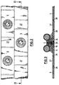
- a combustion furnace for example a waste incineration plant, has one metallic tube wall (1) with water-carrying tubes (2) and connecting them Web (3) or fins on to the combustion chamber (4) are on the Pipe wall (1) lining plates (5) made of refractory ceramic material, in particular SiC material. The surface of the lining plate 5 can be wavy. Between this and the pipe wall (1) is an insulating and Compensation layer (6), for example made of ceramic fiber material.
- Anchor pins (7) made of metal, for example, are distributed on one of the webs (3) Spring steel, welded on.
- the anchor pin (7) has a round or rectangular one Cross-section. It has a longitudinal slot (8) next to the elastic one Tongues (9,10) exist.
- the anchor pin (7) can also be slit two or more times be, whereby there are correspondingly more resilient tongues.
- the Lining plate (5) has a conical recess (19), the Pipe wall (1) facing smaller opening forms a stop edge (20).
- Anchor pin (7) happens approximately as follows:
- the lining plate (5) with its opening forming the stop edge (20) put on the ends (13, 14) of the anchor pin (7) in the direction of the arrow (M), the ends (13, 14) easily fitting into the opening. To make this easier
- the opening can then be attached to the stop edge (20) with a Insertion bevel (21) may be provided. Then it is in the direction of arrow (M) Pressure is exerted on the lining plate (5). It slides under spring elastic Deformation of the tongues (9, 10) of the stop edge (20) on the front slopes (15.16). When he has overcome the front slopes (15, 16), he glides to the rear bevels (17,18) further, the tongues (9,10) resilient snap open.
- the lining plate (5) is now shown in FIG. 1 Position held. In order for the stop edge (20) to lie flat against the To achieve rear slopes (17, 18), the angle of the rear slopes (17, 18) the angle of the conical recess (19).
- the projections (11, 12) project radially beyond the cross section of the anchor pin (7) close to the web (3).
- the cross section of the anchor pin (7) close to the web (3) can also be as large or larger than the cross section in the area in which the front bevels (15, 16) into the pass over the rear slopes (17, 18).
- Recess (19) is aligned with the surface (5.1) of the lining plate (5).
- Compensating bore (26) may be provided.
- Cap (25) Through the seated in the insulating compound (24) Cap (25) is the anchor pin (7) against that in the combustion chamber (4) prevailing corrosive atmosphere and against the temperatures prevailing there, protected, for example, about 1200 ° C.
- an anchor pin (7) attached lining panels (5) arranged in rows overlapping. Between are two lining plates (5) attached to anchor pins (7) Intermediate plates (27) are provided, not on anchor pins, but thereby are held that they and the adjacent lining plates (5) stepped Have edges (28, 29), the stepped edges (29) of the Lining plates (5) the stepped edges (28) of the intermediate plates (27) overlap the combustion chamber (see Fig. 3). It is a single one Replacing defective lining plates (5) in a particularly simple way possible. To replace a destroyed lining plate (5), this is from their anchor pin (7) removed, for example broken down.
- Molded part (30) made of refractory ceramic material attached which is a special has low porosity, especially almost 0% porosity, and high strength owns.
- the molded part (30) can be fixed on the lining plate (5) by that it is in the manufacture of the lining plate (5) in the mass forming it is pressed in, a positive connection being produced via conical surfaces (31).
- the molded part (30) has a cavity (32) in which, following an opening (33) there is a rounded extension (34). According to this are the Projections (11,12) of the tongues (9,10) shaped.
- the lining plate (5) with its molded part (30) in the direction of the arrow (M) on the front slopes (15, 16) of the tongues (9, 10). This deform resiliently when passing through the opening (33) and then snap with their projections (11, 12) into the extension (34) of the Cavity (32).
- the tongues (9, 10) are found on the one hand on the bottom (35) of the Hollow (32) a stop and on the other hand find the rear bevels (17, 18) in the cavity (32) a stop.
- the lining plate (5) is thereby on Anchor pin (7) attached.
- the anchor pin (7) is in against the corrosive atmosphere of the combustion chamber (4) protected because it is opposite the combustion chamber (4) by the Lining plate (5) itself and covered by the molded part (30).
Landscapes
- Engineering & Computer Science (AREA)
- Mechanical Engineering (AREA)
- General Engineering & Computer Science (AREA)
- Physics & Mathematics (AREA)
- Thermal Sciences (AREA)
- Chemical & Material Sciences (AREA)
- Combustion & Propulsion (AREA)
- Furnace Housings, Linings, Walls, And Ceilings (AREA)
- Connection Of Plates (AREA)
Abstract
Description
hinteren Schrägen(17,18) übergehen.
Claims (11)
- Einrichtung zum Befestigen von Auskleidungsplatten aus feuerfestem keramischem Material an einer metallischen Wand, insbesondere einer Müllverbrennungsanlage, wobei an der Wand metallische, geschlitzte Ankerstifte befestigt sind, die die Auskleidungsplatten tragen,
dadurch gekennzeichnet,
daß der Ankerstift (7) wenigstens zwei federelastische Zungen (9,10) bildet und daß an den Zungen (9,10) radiale Vorsprünge (11,12) gestaltet sind, die hinter einen mit der Auskleidungsplatte (5) in Verbindung stehenden Anschlagrand (20) druckknopfartig geschnappt sind. - Einrichtung nach Anspruch 1,
dadurch gekennzeichnet,
daß die Vorsprünge (11,12) vordere Schrägen (15,16) bilden, die unter federelastischem Verschwenken der Zungen (9,10) in eine den Anschlagrand (20) bildende Öffnung der Auskleidungsplatte (5) einschiebbar sind. - Einrichtung nach Anspruch 1 oder 2,
dadurch gekennzeichnet,
daß die Vorsprünge (11,12) hintere Schrägen (17,18) bilden, die an den Anschlagrand (20) geschnappt sind. - Einrichtung nach einem der vorhergehenden Ansprüche,
dadurch gekennzeichnet,
daß auf die Enden (13,14) der Zungen (9,10) eine Kappe (25) aus feuerfestem keramischem Material aufgesetzt ist. - Einrichtung nach Anspruch 4,
dadurch gekennzeichnet,
daß die Kappe (25) in einer konischen, den Anschlagrand (20) bildenden Vertiefung (19) der Auskleidungsplatte (5) liegt. - Einrichtung nach Anspruch 5,
dadurch gekennzeichnet,
daß die Kappe (25) mittels Isoliermasse (24) in der Vertiefung (19) eingebettet ist. - Einrichtung nach einem der vorhergehenden Ansprüche 1 bis 3,
dadurch gekennzeichnet,
daß an der Auskleidungsplatte (5) ein Formteil (30) befestigt ist, das eine die Vorsprünge (11,12) der Zungen (9,10) aufnehmende und den Anschlagrand (20) bildende Höhlung (32) aufweist. - Einrichtung nach Anspruch 7,
dadurch gekennzeichnet,
daß das keramische Formteil (30) eine Porosität von etwa 0% aufweist. - Einrichtung nach einem der vorhergehenden Ansprüche 6 bis 8,
dadurch gekennzeichnet,
daß die Höhlung (32) mit ihrem Boden (35) einen Tiefenanschlag für die Zungen (9,10) bildet. - Einrichtung nach einem der vorhergehenden Ansprüche,
dadurch gekennzeichnet,
daß der Anschlagrand (20) und/oder die an diesen geschnappten Vorsprüge (11,12) einen runden oder rechteckigen Querschnitt bilden. - Einrichtung nach einem der vorhergehenden Ansprüche,
dadurch gekennzeichnet,
daß der Ankerstift (7) wenigstens eine Vertiefung (22) aufweist, in die der Anschlagrand (20) einrastet.
Applications Claiming Priority (2)
| Application Number | Priority Date | Filing Date | Title |
|---|---|---|---|
| DE19825546A DE19825546C1 (de) | 1998-06-08 | 1998-06-08 | Einrichtung zum Befestigen von Auskleidungsplatten |
| DE19825546 | 1998-06-08 |
Publications (2)
| Publication Number | Publication Date |
|---|---|
| EP0964205A2 true EP0964205A2 (de) | 1999-12-15 |
| EP0964205A3 EP0964205A3 (de) | 2000-11-02 |
Family
ID=7870277
Family Applications (1)
| Application Number | Title | Priority Date | Filing Date |
|---|---|---|---|
| EP99110737A Withdrawn EP0964205A3 (de) | 1998-06-08 | 1999-06-04 | Einrichtung zum Befestigen von Auskleidungsplatten |
Country Status (3)
| Country | Link |
|---|---|
| EP (1) | EP0964205A3 (de) |
| CN (1) | CN1239764A (de) |
| DE (1) | DE19825546C1 (de) |
Cited By (3)
| Publication number | Priority date | Publication date | Assignee | Title |
|---|---|---|---|---|
| US6837015B2 (en) | 2001-11-14 | 2005-01-04 | Mitsubishi Heavy Industries, Ltd. | Installation method of fireproof structure for protecting water pipes |
| SG109991A1 (en) * | 2001-11-08 | 2005-04-28 | Mitsubishi Heavy Ind Ltd | Fireproof structure and installation method for protecting water pipes |
| EP1701122A3 (de) * | 2005-03-11 | 2006-12-06 | Plibrico G.m.b.H. | Feuerfestplatte sowie Verfahren zu deren Herstellung |
Families Citing this family (7)
| Publication number | Priority date | Publication date | Assignee | Title |
|---|---|---|---|---|
| KR100361768B1 (ko) * | 1997-11-28 | 2002-11-22 | 미쯔비시 헤비 인더스트리즈 리미티드 | 수관 보호용 내화 구조체와 그 조립방법 |
| EP1236954A1 (de) * | 2001-03-02 | 2002-09-04 | Karrena GmbH | Platten an Kesselrohrwänden |
| FR2840672B1 (fr) * | 2002-06-07 | 2004-12-24 | Lafarge Refractories | Systeme d'accrochage d'un materiau refractaire non faconne sur une paroi tubulaire de chaudiere |
| EP2236928A1 (de) * | 2009-03-17 | 2010-10-06 | Siemens Aktiengesellschaft | Hitzeschildelement eines Hitzeschildes |
| CN106164590B (zh) * | 2014-03-03 | 2019-11-26 | 安萨尔多能源公司 | 燃气轮机组件的燃烧室和用于燃气轮机组件的燃烧室的绝热砖的支撑构件 |
| DE102018200926A1 (de) * | 2018-01-22 | 2019-07-25 | Siemens Aktiengesellschaft | Bauteil zur Positionierung eines Hitzeschildelementes |
| CN110985818A (zh) * | 2019-11-27 | 2020-04-10 | 广东省工业设备安装有限公司 | 一种一体化复合风管的加固钉及加固方法 |
Family Cites Families (8)
| Publication number | Priority date | Publication date | Assignee | Title |
|---|---|---|---|---|
| DE566927C (de) * | 1930-11-18 | 1932-12-24 | Franz Hof | Feuerraumhaengedecke |
| US2413425A (en) * | 1944-09-07 | 1946-12-31 | Plibrico Jointless Firebrick C | Anchor extension means |
| DE1173734B (de) * | 1962-10-11 | 1964-07-09 | Siemens Ag | Brennkammer, insbesondere fuer Gasturbinen, mit einer aus feuerfesten Steinen aufgebauten Auskleidung |
| GB8912889D0 (en) * | 1989-06-05 | 1989-07-26 | Williamson Cliff Limited | Refractory lining of furnaces |
| DE9017334U1 (de) * | 1990-12-20 | 1991-03-07 | K + K Ofenbau GmbH, 4040 Neuss | Brennkammer-Wandabkleidung |
| GB2265411A (en) * | 1992-03-26 | 1993-09-29 | Swintex | Quick release toggle; barrier system |
| DE19502730A1 (de) * | 1995-01-28 | 1996-08-01 | Abb Management Ag | Keramische Auskleidung |
| DE19611532C1 (de) * | 1996-03-23 | 1997-06-12 | Didier Werke Ag | Feuerraumwandung |
-
1998
- 1998-06-08 DE DE19825546A patent/DE19825546C1/de not_active Expired - Fee Related
-
1999
- 1999-06-04 EP EP99110737A patent/EP0964205A3/de not_active Withdrawn
- 1999-06-08 CN CN 99108326 patent/CN1239764A/zh active Pending
Cited By (5)
| Publication number | Priority date | Publication date | Assignee | Title |
|---|---|---|---|---|
| SG109991A1 (en) * | 2001-11-08 | 2005-04-28 | Mitsubishi Heavy Ind Ltd | Fireproof structure and installation method for protecting water pipes |
| US7204061B2 (en) | 2001-11-08 | 2007-04-17 | Mitsubishi Heavy Industries, Ltd. | Fireproof structure and installation method for protecting water pipes |
| US6837015B2 (en) | 2001-11-14 | 2005-01-04 | Mitsubishi Heavy Industries, Ltd. | Installation method of fireproof structure for protecting water pipes |
| SG109999A1 (en) * | 2001-11-14 | 2005-04-28 | Mitsubishi Heavy Ind Ltd | Installation method of fireproof structure for protecting water pipes |
| EP1701122A3 (de) * | 2005-03-11 | 2006-12-06 | Plibrico G.m.b.H. | Feuerfestplatte sowie Verfahren zu deren Herstellung |
Also Published As
| Publication number | Publication date |
|---|---|
| DE19825546C1 (de) | 1999-08-26 |
| EP0964205A3 (de) | 2000-11-02 |
| CN1239764A (zh) | 1999-12-29 |
Similar Documents
| Publication | Publication Date | Title |
|---|---|---|
| DE2718170C3 (de) | Befestigungsclip für verkleidete Abdeckplatten, insbesondere für Kraftfahrzeuge | |
| EP1211137B1 (de) | Verbindungselement | |
| DE19825546C1 (de) | Einrichtung zum Befestigen von Auskleidungsplatten | |
| EP0641939A1 (de) | Verbindungselement | |
| DE10231203A1 (de) | Targetträgeranordnung | |
| DE20104406U1 (de) | Kraftfahrzeugsichtscheibenspritzwasserzuführanordnung | |
| EP0287973B1 (de) | Hinterlüftete Fassadenverkleidung | |
| EP0280107A1 (de) | Wasser/Luft-Kühler | |
| EP0611855B1 (de) | Anordnung zum Verbinden zweier Rohrabschnitte des keramischen Innenrohres eines Schornsteins | |
| EP0479011B1 (de) | Lüfterhaube zur Befestigung an dem Kühler einer Brennkraftmaschine | |
| DE29921227U1 (de) | Linearverbinder aus Kunststoff für Abstandhalterrahmen von Mehrscheibenisoliergläsern | |
| EP0939270A1 (de) | Strahlrohranordnung | |
| DE3415370A1 (de) | Luftausblasduese einer anlage zur raumbelueftung | |
| DE102007037566A1 (de) | Vorgehängte Plattenkonstruktion | |
| DE29508292U1 (de) | Befehlsgerät | |
| DE29808857U1 (de) | Steckdosenleiste | |
| DE19608941C2 (de) | Bügellagerung mit Rasteinrichtung für einen Farbroller oder dergleichen | |
| DE20207685U1 (de) | Halter | |
| DE29918002U1 (de) | Linearverbinder aus Kunststoff für Abstandhalterprofile von Mehrscheibenisoliergläsern | |
| EP0963496A1 (de) | Fassaden-befestigungsvorrichtung | |
| EP2055856A2 (de) | Dachkonstruktion | |
| EP1838987A1 (de) | Anschlussvorrichtung für medienleitungen | |
| DE10137842A1 (de) | Bauteil zur Aufnahme in ein Karosserieteil, insbesondere Leuchte | |
| EP4348115A1 (de) | Haltevorrichtung zur halterung eines keramischen ankersteins an einer ofenwand, ein eine solche haltevorrichtung umfassender ofen sowie ein verfahren zur befestigung einer solchen haltevorrichtung an einer ofenwand | |
| DE102009039390A1 (de) | Korrosionsschutzkörper |
Legal Events
| Date | Code | Title | Description |
|---|---|---|---|
| PUAI | Public reference made under article 153(3) epc to a published international application that has entered the european phase |
Free format text: ORIGINAL CODE: 0009012 |
|
| AK | Designated contracting states |
Kind code of ref document: A2 Designated state(s): AT BE CH CY DE DK ES FI FR GB GR IE IT LI LU MC NL PT SE |
|
| AX | Request for extension of the european patent |
Free format text: AL;LT;LV;MK;RO;SI |
|
| PUAL | Search report despatched |
Free format text: ORIGINAL CODE: 0009013 |
|
| AK | Designated contracting states |
Kind code of ref document: A3 Designated state(s): AT BE CH CY DE DK ES FI FR GB GR IE IT LI LU MC NL PT SE |
|
| AX | Request for extension of the european patent |
Free format text: AL;LT;LV;MK;RO;SI |
|
| AKX | Designation fees paid | ||
| STAA | Information on the status of an ep patent application or granted ep patent |
Free format text: STATUS: THE APPLICATION IS DEEMED TO BE WITHDRAWN |
|
| 18D | Application deemed to be withdrawn |
Effective date: 20010503 |
|
| REG | Reference to a national code |
Ref country code: DE Ref legal event code: 8566 |