EP0964213A2 - Verfahren und Vorrichtung zum Verhindern des Austritts eines Kältemittels aus einem Kühlraum - Google Patents
Verfahren und Vorrichtung zum Verhindern des Austritts eines Kältemittels aus einem Kühlraum Download PDFInfo
- Publication number
- EP0964213A2 EP0964213A2 EP99500094A EP99500094A EP0964213A2 EP 0964213 A2 EP0964213 A2 EP 0964213A2 EP 99500094 A EP99500094 A EP 99500094A EP 99500094 A EP99500094 A EP 99500094A EP 0964213 A2 EP0964213 A2 EP 0964213A2
- Authority
- EP
- European Patent Office
- Prior art keywords
- port
- enclosure
- vapor
- refrigerant fluid
- refrigeration
- Prior art date
- Legal status (The legal status is an assumption and is not a legal conclusion. Google has not performed a legal analysis and makes no representation as to the accuracy of the status listed.)
- Granted
Links
- 238000005057 refrigeration Methods 0.000 title claims abstract description 130
- 238000000034 method Methods 0.000 title claims abstract description 44
- 239000003507 refrigerant Substances 0.000 title claims description 45
- 239000012530 fluid Substances 0.000 title claims description 37
- 230000014759 maintenance of location Effects 0.000 title description 4
- 238000011084 recovery Methods 0.000 claims description 27
- 238000012544 monitoring process Methods 0.000 claims description 11
- 230000007704 transition Effects 0.000 claims description 6
- 230000008878 coupling Effects 0.000 claims 1
- 238000010168 coupling process Methods 0.000 claims 1
- 238000005859 coupling reaction Methods 0.000 claims 1
- 230000009471 action Effects 0.000 abstract description 4
- 230000005574 cross-species transmission Effects 0.000 description 21
- 239000007789 gas Substances 0.000 description 16
- 238000001764 infiltration Methods 0.000 description 16
- 230000008595 infiltration Effects 0.000 description 16
- 230000000694 effects Effects 0.000 description 14
- 238000002347 injection Methods 0.000 description 14
- 239000007924 injection Substances 0.000 description 14
- 238000013461 design Methods 0.000 description 9
- 238000002955 isolation Methods 0.000 description 9
- 238000004064 recycling Methods 0.000 description 9
- 230000008901 benefit Effects 0.000 description 8
- 238000000605 extraction Methods 0.000 description 8
- 230000003068 static effect Effects 0.000 description 8
- 238000012360 testing method Methods 0.000 description 8
- 230000008859 change Effects 0.000 description 6
- 230000007423 decrease Effects 0.000 description 6
- 230000004888 barrier function Effects 0.000 description 5
- 238000004140 cleaning Methods 0.000 description 5
- 238000001816 cooling Methods 0.000 description 5
- 238000012937 correction Methods 0.000 description 5
- 230000006870 function Effects 0.000 description 5
- 230000001419 dependent effect Effects 0.000 description 4
- 238000010790 dilution Methods 0.000 description 4
- 239000012895 dilution Substances 0.000 description 4
- 238000010586 diagram Methods 0.000 description 3
- 230000002028 premature Effects 0.000 description 3
- 230000009467 reduction Effects 0.000 description 3
- 238000011144 upstream manufacturing Methods 0.000 description 3
- XLYOFNOQVPJJNP-UHFFFAOYSA-N water Chemical compound O XLYOFNOQVPJJNP-UHFFFAOYSA-N 0.000 description 3
- IJGRMHOSHXDMSA-UHFFFAOYSA-N Atomic nitrogen Chemical compound N#N IJGRMHOSHXDMSA-UHFFFAOYSA-N 0.000 description 2
- CURLTUGMZLYLDI-UHFFFAOYSA-N Carbon dioxide Chemical compound O=C=O CURLTUGMZLYLDI-UHFFFAOYSA-N 0.000 description 2
- 238000013459 approach Methods 0.000 description 2
- 238000009530 blood pressure measurement Methods 0.000 description 2
- 230000003750 conditioning effect Effects 0.000 description 2
- 239000000356 contaminant Substances 0.000 description 2
- 238000011109 contamination Methods 0.000 description 2
- 230000003247 decreasing effect Effects 0.000 description 2
- 238000007710 freezing Methods 0.000 description 2
- 230000008014 freezing Effects 0.000 description 2
- 230000005484 gravity Effects 0.000 description 2
- 230000006872 improvement Effects 0.000 description 2
- 239000007788 liquid Substances 0.000 description 2
- 238000005259 measurement Methods 0.000 description 2
- 238000012986 modification Methods 0.000 description 2
- 230000004048 modification Effects 0.000 description 2
- 238000013517 stratification Methods 0.000 description 2
- 230000002411 adverse Effects 0.000 description 1
- 238000000429 assembly Methods 0.000 description 1
- 230000000712 assembly Effects 0.000 description 1
- 230000015572 biosynthetic process Effects 0.000 description 1
- 238000007664 blowing Methods 0.000 description 1
- 229910002092 carbon dioxide Inorganic materials 0.000 description 1
- 239000001569 carbon dioxide Substances 0.000 description 1
- 238000004891 communication Methods 0.000 description 1
- 230000001276 controlling effect Effects 0.000 description 1
- 238000011161 development Methods 0.000 description 1
- 238000007865 diluting Methods 0.000 description 1
- 238000003780 insertion Methods 0.000 description 1
- 230000037431 insertion Effects 0.000 description 1
- 238000009434 installation Methods 0.000 description 1
- 238000012423 maintenance Methods 0.000 description 1
- 238000004519 manufacturing process Methods 0.000 description 1
- 230000007246 mechanism Effects 0.000 description 1
- 238000002156 mixing Methods 0.000 description 1
- 238000012806 monitoring device Methods 0.000 description 1
- 229910052757 nitrogen Inorganic materials 0.000 description 1
- 230000037361 pathway Effects 0.000 description 1
- 230000000737 periodic effect Effects 0.000 description 1
- 230000008569 process Effects 0.000 description 1
- 230000001105 regulatory effect Effects 0.000 description 1
- 238000007789 sealing Methods 0.000 description 1
- 239000000243 solution Substances 0.000 description 1
- 238000010257 thawing Methods 0.000 description 1
- 230000032258 transport Effects 0.000 description 1
- 230000008016 vaporization Effects 0.000 description 1
- 230000000007 visual effect Effects 0.000 description 1
Images


Classifications
-
- F—MECHANICAL ENGINEERING; LIGHTING; HEATING; WEAPONS; BLASTING
- F25—REFRIGERATION OR COOLING; COMBINED HEATING AND REFRIGERATION SYSTEMS; HEAT PUMP SYSTEMS; MANUFACTURE OR STORAGE OF ICE; LIQUEFACTION SOLIDIFICATION OF GASES
- F25D—REFRIGERATORS; COLD ROOMS; ICE-BOXES; COOLING OR FREEZING APPARATUS NOT OTHERWISE PROVIDED FOR
- F25D29/00—Arrangement or mounting of control or safety devices
- F25D29/001—Arrangement or mounting of control or safety devices for cryogenic fluid systems
-
- F—MECHANICAL ENGINEERING; LIGHTING; HEATING; WEAPONS; BLASTING
- F25—REFRIGERATION OR COOLING; COMBINED HEATING AND REFRIGERATION SYSTEMS; HEAT PUMP SYSTEMS; MANUFACTURE OR STORAGE OF ICE; LIQUEFACTION SOLIDIFICATION OF GASES
- F25B—REFRIGERATION MACHINES, PLANTS OR SYSTEMS; COMBINED HEATING AND REFRIGERATION SYSTEMS; HEAT PUMP SYSTEMS
- F25B1/00—Compression machines, plants or systems with non-reversible cycle
-
- F—MECHANICAL ENGINEERING; LIGHTING; HEATING; WEAPONS; BLASTING
- F25—REFRIGERATION OR COOLING; COMBINED HEATING AND REFRIGERATION SYSTEMS; HEAT PUMP SYSTEMS; MANUFACTURE OR STORAGE OF ICE; LIQUEFACTION SOLIDIFICATION OF GASES
- F25D—REFRIGERATORS; COLD ROOMS; ICE-BOXES; COOLING OR FREEZING APPARATUS NOT OTHERWISE PROVIDED FOR
- F25D3/00—Devices using other cold materials; Devices using cold-storage bodies
- F25D3/10—Devices using other cold materials; Devices using cold-storage bodies using liquefied gases, e.g. liquid air
- F25D3/11—Devices using other cold materials; Devices using cold-storage bodies using liquefied gases, e.g. liquid air with conveyors carrying articles to be cooled through the cooling space
Definitions
- This invention relates to a method and apparatus for improving the overall efficiency of a refrigeration enclosure and, more particularly, to an improved method and apparatus for retaining a refrigerant fluid within the refrigeration enclosure.
- the refrigerant is a cryogenic fluid that is vaporized during the refrigeration process.
- air manages to enter the refrigeration enclosure through ports which allow product to pass into and out of the enclosure.
- the air is much warmer and contains a considerable amount of moisture relative to the environment inside the enclosure.
- the moist air can be thought of as a contaminant in the sense that it reduces the purity level of the vapor inside the enclosure.
- Refrigeration efficiency is defined as the quantity of heat removed from a product being cooled, compared to the amount of refrigeration being expended by the cryogen.
- Cooling of air instead of product decreases the cooling potential of the refrigerant, and hence decreases refrigeration efficiency.
- freezing of the water vapor can potentially lead to a damaging build-up of ice inside the enclosure. Ice build-up can become severe enough to require a stop in the production line of the product being cooled, to allow for a thawing period.
- the cooling potential of the refrigerant is reduced or lost during this thaw cycle. The net result is a higher cost in operation.
- the best approach is to start with the purest stream possible from the source, which in this case is a refrigeration enclosure.
- the economics associated with recycling a refrigerant are greatly impacted by relatively small changes in the purity of the vapor inside the enclosure. Hence, the greatest economic advantage is achieved when air infiltration is minimized.
- a tunnel refrigeration enclosure has an entrance port to allow product to enter the enclosure, an exit port to allow product to leave the enclosure, and a flat conveyor in-between.
- a spiral refrigeration enclosure has similar porting, except that the ports are at different heights relative to the base of the refrigeration enclosure. Inside the enclosure, the conveyor follows a spiral or helical pattern between the ports.
- U.S. Patent No. 3,728,869 to Schmidt describes the recycling of cryogenic vapors from an enclosure (primarily a spiral refrigerator).
- the pressure within the refrigeration enclosure is kept above atmospheric pressure to minimize air and other contaminant infiltration, and pressure and gravitational effects cause a flow thereof from each refrigeration port.
- the exiting vapor is collected in adjacent vestibules or spillover boxes in such a manner as to form a vapor barrier above the vestibule. Air infiltration is prevented by a vapor dam.
- Vapor is removed from the bottom of a vestibule by a piping network driven by a blower system. Control of vapor removal is through motorized on/off dampers in the ducting leading away from the vestibules.
- U.S. Patent No. 4,356,707 to Tyree et al. describes several refrigeration enclosure designs which utilize both mechanical and cryogenic refrigeration.
- a spiral refrigeration enclosure using a cryogenic refrigerant is described wherein diluting chambers are positioned adjacent the refrigeration ports. The concern at a lower port is to minimize outflow of the denser-than-air cryogen vapor from the refrigeration enclosure.
- a chamber adjacent to the lower port includes several baffles and a blower system operated at a constant frequency. Vapor is retarded from leaving the refrigeration enclosure by sucking a portion of the vapor from a dilution chamber and redirecting it back into the enclosure. The remaining portion of the vapor exits through the refrigeration enclosure opening and dilutes any air trying to enter the enclosure. Side vanes, manually positioned, are used to balance flow across a conveyor belt.
- Variable fan speed control has been employed in the prior art as a means to prevent premature spillover of cryogenic vapor from a refrigeration enclosure or to prevent air from entering.
- U.S. Patents 4,528,819 (Klee) and 4,800,728 (Klee) the concern is how to prevent loss of cryogen vapor from a refrigeration enclosure or air infiltrating into the enclosure.
- a temperature sensor is used to indicate whether cryogenic vapor is leaving the enclosure or air is entering the enclosure. Coupled to the temperature sensor is a blower system.
- the blower is on the exhaust line of the refrigeration enclosure.
- U.S. Patent No. 4,800,728, the blower mechanism is internal to the refrigeration enclosure and is part of the circulation system.
- U.S. Patent No. 4,947,654 (Sink et al.) describes atmosphere control within spiral refrigerators and tunnel refrigerators.
- the blower or blowers of the dilution system are no longer operated at a fixed frequency, but control of the blower system is now coupled to the cryogen injection rate.
- the primary sensing device can be either a temperature sensor inside the enclosure or a pressure sensor in the liquid supply line that feeds the cryogen injectors.
- the exit port can have a similar system to prevent air infiltration by letting a small amount of vapor exit through the port.
- Similar means are discussed for minimizing air infiltration and reducing the premature loss of vapor from the refrigerator.
- U.S. Patent No. 4,955,206 discusses a variable speed control method for maintaining the environment within a refrigerator.
- maintenance of the internal environment is enhanced by the addition of a photocell transmitter and receiver sensor system located outside the entrance port and a baffle-linkage scheme surrounding one of the internal axial fans.
- the sensor system provides control information based upon how much vapor is leaving the refrigerator. If an excessively high level of vapor is escaping, the baffle-linkage system directs flow away from the port. If the opposite is true, the baffle-linkage responds by directing vapor toward the port.
- the dilution blower system is coupled to the photocell sensing system and is not dependent on the injection rate. In both refrigerator configurations, the blower systems have either variable or single speed drives.
- U.S. Patent No. 5,186,008 (Appolonia et al.) discusses a method for controlling an amount of vapor extracted from an enclosure as part of a recycle effort.
- the locations of suction are at an upper vestibule and at the bottom of the refrigeration enclosure.
- the amount of vapor leaving the enclosure is a constant ratio relative to the injection rate.
- the remaining portion of vapor resulting from injected cryogen exits through the entrance and exit ports.
- Sufficient suction needs to be applied at the upper vestibule to minimize gravitational effects on the vapor flow leaving through the lower port and to prevent air infiltration in the upper port.
- the pressure in the upper vestibule region is required to be the lowest pressure relative to the refrigeration enclosure and the surrounding atmosphere.
- Control apparatus incorporating the invention is installed inside a refrigeration enclosure, adjacent to a port, preferably at the lowermost port. If the enclosure contains multiple ports at similar height, then each port has a form of the control apparatus attached to it.
- the control apparatus adjusts a flow of vapor leaving the interior of the enclosure.
- the control apparatus includes a duct assembly and a blower system.
- the bottom portion of the duct assembly is a tunnel enclosure through which a conveyor belt passes. Connected to an inside edge of the tunnel enclosure is a duct that extends upward from the conveyor belt.
- a blower system for this duct either sucks vapor away from the conveyor belt or blows vapor from the enclosure interior toward the belt. Regardless of the flow direction, a vapor curtain forms inside the tunnel enclosure and represents a transitional region, from all vapor to all air. To assist the formation of the vapor curtain, a further suction duct assembly is connected to the outer edge of the tunnel and spans the conveyor belt. This duct draws the exiting vapor toward the top of the tunnel enclosure. Hence, a major portion of the vapor gets directed back into the refrigeration enclosure while a small amount of vapor leaves the enclosure to prevent air contamination. A gas analyzer is used to measure the vapor concentration level in the tunnel.
- Control of the blower for the duct assembly is based on vapor concentrations in the tunnel enclosures adjacent to each port. At regular intervals, the vapor concentration level at each port is measured. A microprocessor compares the measured concentration levels and alters the blower motor frequency in such a manner as to minimize the difference in concentration levels at each port.
- a vapor curtain balance is established.
- a relatively high purity vapor stream can be withdrawn from the enclosure through a third port without affecting the vapor curtain balance of the refrigeration enclosure.
- Internal blowers within the enclosure can advantageously provide circulation and mixing of the vapor throughout the enclosure to minimize stratification of the vapor and permit removal of a high purity vapor stream from any point within the refrigeration enclosure.
- Figure 1 is a schematic view of a refrigeration enclosure with a spiral conveyor, which refrigeration enclosure incorporates the invention hereof.
- FIG. 2 is a schematic view of a refrigeration enclosure with a spiral conveyor and center cage fan, which refrigeration enclosure incorporates the invention hereof.
- Figures 3, 4 and 5 depict a detailed view of a tunnel/ducting arrangement positioned at a first port of the refrigeration enclosure of Figure 1 with and without exit baffles.
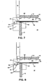
- Figures 6, 7 and 8 depict a detailed view of a tunnel/ducting arrangement positioned at a second port of the refrigeration enclosure of Figure 1 with and without exit baffles.
- Figure 9 is a schematic block diagram of control apparatus for the invention incorporated in the refrigeration enclosure of Figure 1.
- Figure 10 is a schematic illustration of exhaust ducting from a refrigeration enclosure to a refrigeration unit, wherein the exhaust ducting is controlled to maintain a desired refrigerant concentration in the refrigeration enclosure and the ducting.
- Figure 11 is a schematic block diagram of control apparatus for the exhaust ducting from the refrigeration enclosure of Figure 10.
- Figure 12 is a schematic view of a tunnel refrigeration enclosure which incorporates the invention hereof.
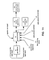
- Figure 13 is a schematic block diagram of control apparatus for the invention incorporated in the tunnel refrigeration enclosure of Figure 12.
- Figure 14 is a detailed view of a modified tunnel/ducting arrangement for the spiral refrigeration enclosure of Figure 1.
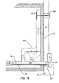
- Figure 15 is a schematic view of a first alternative embodiment of a tunnel/ducting arrangement at a refrigeration enclosure port.
- Figure 16 is a schematic view of a second alternative embodiment of a tunnel/ducting arrangement at a refrigeration enclosure port.
- Figure 17 is a schematic view of a third alternative embodiment of a tunnel/ducting arrangement at a refrigeration enclosure port.
- a refrigeration enclosure 10 includes insulated walls, base, top and an interior volume 12.
- One or more circulating fans 13 are positioned about interior volume 12.
- a conveyor belt 16 having a helical or spiral pattern, transports product through refrigeration enclosure 10.
- the product to be cooled passes through a lower port 14 and exits refrigeration enclosure 10 through an upper port 15 or vice versa. While the following discussion is specific to a spiral refrigeration enclosure, other refrigeration designs such as a tunnel configuration can utilize the invention.
- a set of injectors and associated piping (not shown) deliver a cryogenic fluid (e.g. carbon dioxide, nitrogen, etc.) into the volume 12.
- the refrigeration control system is temperature based and provides a signal to a modulating valve on the incoming cryogenic feed line to deliver the amount of cryogen fluid necessary to reach a given temperature within the enclosure.
- refrigeration enclosure 10 includes a duct assembly 17 at inlet port 14.
- Duct assembly 17 provides a means to suck refrigerant vapor away from conveyor belt 16.
- Duct assembly 17 spans conveyor belt 16.
- Inlet port 14 of enclosure 10 couples to a low clearance outer tunnel 20 and an under-the-belt flat plate 35.
- the upper run of conveyor belt 16 passes over flat plate 35 and through outer tunnel 20 while the lower run of belt 16 does not.
- Baffle 32 lies between the upper and lower runs of conveyor belt 16 to prevent premature egress of vapor from the enclosure.
- Duct assembly 17 opens into interior volume 12 at aperture 21, which is the leading edge of an inner tunnel 22.
- At the junction of tunnels 20, 22 is a vertical duct 23.
- the bottom edge of vertical duct 23 has the lowest clearance relative to the conveyor belt.
- Outer tunnel 20 connects to vertical duct 23 slightly above the bottom edge to establish a small retention cavity along the top of outer tunnel 20.
- the retention cavity functions to dilute the air that gets into outer tunnel 20 to minimize air contamination reaching the interior of enclosure 10.
- Under-the-belt plate 35 extends from slightly beyond the enclosure 10 to at least slightly beyond vertical duct 23 so that plate 35 extends to the extreme edge of tunnel 20, and to about the edge of tunnel 22.
- the second end of vertical duct 23 attaches to a ninety degree bend 24, which allows a transition in the width of the ducting.
- Attached to the second end of bend 24 is a horizontal duct 25 which spans belt 16 but is wider than vertical duct 23.
- Horizontal duct 25 terminates at a plate 34 having dimensions similar to horizontal duct 25. Plate 34 includes openings to accommodate fans 26. It is preferred that two, multiple bladed, center hub blower fans 26 be mounted side by side.
- Fans 26 are driven by motors 27 externally mounted to refrigeration enclosure 10.
- the vapor that exits horizontal duct 25 impacts the enclosure wall in region 28 and is dispersed into interior 12. Baffles can be used to direct the vapor flow upwards (relative to horizontal duct 25), downwards, or sideways back into interior volume 12.
- the present embodiment sucks refrigerant vapor away from conveyor belt 16, as indicated by the arrows in Figure 3.
- a small portion of the vapor leaves enclosure 10 through outer tunnel 20, while the major portion of the vapor is redirected into interior volume 12 of enclosure 10.
- the vapor that escapes through lower port 14 is collected in a spillover box 31.
- Spillover box 31 is cleared by an exhaust system schematically represented by external vertical duct 33. In this fashion, vapor is exhausted out of the room containing enclosure 10 and away from personnel.
- a spillover baffle 38 within spillover box 31 under the lower run of conveyor belt 16, that extends horizontally from the outside wall of enclosure 10 to slightly beyond conveyor belt roller 29 and then vertically to slightly below the upper run of conveyor belt 16.
- Spillover baffle 38 collects vapor escaping from inlet port 14 to create a further barrier against the outflow of vapor.
- spillover box 31 contains a spillover baffle 42 that extends along the contour of the lower run of conveyor belt 16 and around conveyor belt roller 29 to slightly below the upper run of conveyor belt 16.
- a roller baffle 41 is located adjacent to conveyor belt roller 29 in between the upper and lower runs of conveyor belt 16. Roller baffle 41 and spillover baffle 42 create further barriers against the outflow of vapor.
- Outlet port 15 of refrigeration enclosure 10 is also locally modified by additional duct work (see Figure 6).
- Outlet port 15, like inlet port 14, has a tunnel-shaped enclosure 49 formed by several interconnecting pieces to impede air entering and vapor escaping.
- An under-the-belt plate 50 begins just forward of conveyor belt roller 59 and extends into refrigeration enclosure 10.
- Tunnel side pieces (not shown) begin at the edge of the refrigeration wall and extend into the enclosure.
- the interior edge of under-the-belt plate 50 and the interior edge of the side pieces should form a common edge inside the enclosure 10.
- Top 51 of tunnel 49 is the refrigeration enclosure ceiling.
- a vertically positioned baffle 52 that spans conveyor belt 16 is also affixed to refrigeration ceiling 51. The clearance between baffle 52 and conveyor belt 16 is determined by the product being cooled and preferably is adjustable.
- Baffle 52 should be contained by the sides of tunnel 49, but does not have to be located at the interior edges of the side pieces.
- outlet port 15 is determined by the height of over-the-belt pickup unit 53. Like the vertically positioned baffle 52, the clearance of over-the-belt pickup unit 53 off conveyor belt 16 is determined by the product to be cooled. With this tunnel configuration, a retention cavity is formed similar to the one in outer tunnel 20 near lower port 14. Additional baffles 54 are placed between the upper and lower layers of conveyor belt 16 to minimize the inlet of air and the outlet of vapor. A spillover box 55 collects the vapor exiting from outlet port 15 and is exhausted via duct 56.
- a spillover baffle 57 is located within spillover box 55 under the lower run of conveyor belt 16 extending horizontally from the outside wall of enclosure 10 to slightly beyond conveyor belt roller 59 and then vertically to slightly below the upper run of conveyor belt 16. Spillover baffle 57 collects vapor exiting from outlet port 15 creating a further barrier against the outflow of vapor.
- spillover box 55 contains a spillover baffle 62 that extends along the contour of the lower run of conveyor belt 16 and around conveyor belt roller 59 to slightly below the upper run of conveyor belt 16.
- a roller baffle 61 is located adjacent to conveyor belt roller 59 in between the upper and lower runs of conveyor belt 16. Roller baffle 61 and spillover baffle 62 create further barriers against the outflow of vapor.
- both ports (14 and 15) have an over-the-belt pick-up unit (30 and 53).
- Each over-the-belt pickup unit (30 and 53) has a positive seal to adjacent tunnels (20 and 49) as depicted in Figures 3 and 6.
- Suction for over-the-belt pickup unit (30 and 53) is provided by the exhaust system, here shown as external ducts 33 and 56.
- the function of this pickup unit is two-fold. First, it minimizes the amount of air that enters into a tunnel. Second, it tends to cause any exiting cryogenic vapor to raise off of conveyor belt 16 and combats the effect of gravity on the vapor. By keeping the vapor level as high as possible in a tunnel, any air that enters a tunnel is diluted. In addition, an over-the-belt pickup unit has been found to minimize vapor stratification inside a tunnel.
- a control procedure for refrigeration enclosure 10 is based on monitoring vapor concentrations near each of ports 14 and 15.
- the sensing system includes gas analyzers to monitor the vapor concentration in each tunnel configuration. Therefore, outer tunnel 20 has a sensor port 40 and upper tunnel 49 has a sensor port 60. In general, the preferred sensor location is inboard from the leading edge of the over-the-belt pickup units 30 and 53.
- the control procedure is based on the difference in cryogenic gas concentrations between the two tunnels. For comparison purposes, it is preferred to use a single analyzer for monitoring both locations. Therefore, an appropriate network of pipe/tubing, automatically controlled valves and a timing device are required (not shown).
- Figure 9 illustrates a microprocessor 81 which provides a means to control the timing of the valves as required to obtain acceptable readings from each location using gas analyzer 80.
- An algorithm based primarily on the difference in concentrations in each tunnel provides a frequency setting signal to variable speed drive 82, which drives fan motors 27. The algorithm optimizes frequency control to the extent that a minimum is achieved in the difference in concentrations. A predetermined setpoint pattern is not used. Essentially, the correction to the frequency of variable speed drive 82 is based on the magnitude of the difference in concentrations. The larger the difference, the greater the correction to the frequency level.
- the algorithm essentially has two modes: a near steady state condition or non-steady state.
- the control algorithm is an endless loop that does the following: collects vapor concentration samples from each tunnel following a predetermined time interval, compares the samples collected, and corrects fan frequency based on the difference in the samples.
- the fan frequency is corrected as a function of the rate of change of the injection rate and/or the rate of change of the refrigeration enclosure temperature.
- Duct assembly 17 establishes a vapor curtain in outer tunnel 20.
- the term vapor curtain is defined here to mean a vapor front where transition occurs from all vapor (concentration level of interior volume 12) to all air. The thickness of this front is not critical, except that it needs to be contained in outer tunnel 20. If the front resides outside port 14, then blower motors 27 are not rotating fast enough. If no vapor front forms in tunnel 20, then the motors 27 are rotating too fast.
- the key to maintaining a high purity level inside enclosure 10 is the establishment of a vapor curtain or front in outer tunnel 20. This is only successful if the upper outlet port 15 and the lower inlet port 14 are in gaseous communication with each other. When a vapor curtain forms in tunnel 20, a vapor front is also formed in tunnel 49.
- the present invention permits withdrawal of a high purity vapor stream, assuming a vapor curtain balance system is in place and operating.
- the internal blower system (fan units 13 or center cage fan unit 11), provides a well mixed environment. Since a thoroughly mixed environment is contained within the enclosure 10, a high purity vapor stream can be withdrawn from interior volume 12 anywhere on or within enclosure 10. Accordingly, the high purity vapor stream may be withdrawn from any location including, for example, at or near an exterior wall of enclosure 10, at or near ports 14 or 15, and at or near the center of interior volume 12. Such a high purity vapor stream may be removed as a controlled exhaust, and then liquefied and reintroduced into enclosure 10.
- a withdrawal port 101 includes ducting 102 that is sealed to the insulated ceiling of enclosure 10.
- a plate 100 is located below the lower end of duct 102 to protect the duct during cleaning of the enclosure.
- the opposite end of duct 102 is connected to an isolation valve 103.
- Additional ducting 104 is connected to the opposite end of isolation valve 103.
- the downstream end of duct 104 connects to a blower housing 105, which is driven by a motor 106.
- the duct assembly extending from withdrawal port 101 to blower housing 105 will contain a vapor having a subatmospheric pressure and therefore, proper sealing of the ductwork is required.
- additional ducting 107 Connected to the outlet of blower housing 105 is additional ducting 107 which terminates at an isolation valve 108.
- isolation valve 108 is a refrigeration system 120 to liquefy the vapor stream for recycling purposes.
- Ducting 107 downstream of blower housing 105 contains a number of devices including a static pressure sensing location 110, a temperature indicator 111, a gas flow metering device 113, and a modulating valve 109. Modulating valve 109 is required to permit, when necessary, a portion or all of the vapor stream to be diverted away from refrigeration system 120. Static pressures are used to monitor the operational characteristics of blower housing 105 (via readings from pressure sensor 115 in ductwork 104 upstream of blower housing 105 and from pressure sensor 110 in ductwork 107 downstream of blower housing 105). Upstream of blower housing 105 is a gas analyzer 112.
- Extraction of vapor from enclosure 10 is precisely controlled and is dependent on the control system for the vapor curtain balance system.
- control of the extraction of a vapor stream (recovery line blower motor frequency) from enclosure 10 is based on a comparison in gas concentrations inside the tunnels (20 and 49) and vapor stream in the recovery line ductwork 104.
- the tunnel concentration value can be either an average value of the monitored concentrations at each sensor (40 and 60) or a single measurement taken at either sensor.
- the underlying principal of the control procedure is to maintain the highest concentrations in the recovery line, and, secondarily, to maximize the flow of extracted vapor without collapsing the vapor fronts that are established in the tunnels.
- Testing has shown that control of the recovery line blower motor frequency can be achieved with considerable difference in the concentration values, on the order of 10 percent to 50 percent.
- the control procedure monitors the concentrations and maintains the difference between the concentrations within a predetermined maximum offset value.
- the correction to the blower frequency is based on the magnitude of the difference in concentrations and how close the maximum offset value is being satisfied. A decrease in a tunnel gas concentration will obviously occur before the recovery line concentration decreases. Furthermore, a significant reduction in the injection rate is used to indicate that the concentration level in enclosure 10 is expected to decrease.
- Mode one has first isolation valve 103 on the recovery line closed. This condition is the same as if the recovery line was not attached to the enclosure.
- the recovery line control system is essentially idle.
- microprocessor 81 provides control signals to modulating valve 109 and to variable speed drive 130, which operates the blower motor 106 at the correct frequency.
- Mode two has first isolation valve 103 open, but second isolation valve 108 closed.
- the recovery line behaves like an exhaust line, as all vapor leaving through withdrawal port 101 exits the recovery line through modulating valve 109. This condition will occur if there is a sudden problem with refrigeration system 120. By quickly redirecting the flow, impact on the environment of interior volume 12 is kept to a minimum.
- Mode three the typical mode of operation, occurs when both isolation valves 103 and 108 are open. In this mode, vapor is withdrawn from enclosure 10 and is sent to refrigeration system 120. Again, the objective of the control procedure is to maximize the vapor concentration level in the recovery line.
- the recovery line control procedure is dependent on the vapor curtain control procedure.
- the vapor balance curtain scheme essentially balances the refrigeration to provide a fixed loss of vapor out of refrigeration enclosure ports 14 and 15. The remaining portion of vapor exits enclosure 10 through the recovery line. If the extraction rate from enclosure 10 is too great, the vapor balance system indicates an upset by an increase in air infiltration since too much vapor is being removed. If the extraction rate is too low, the recovery line system is not optimized and flow through blower housing 105 needs to be increased. If the flow in the recovery line meets the capacity of the refrigeration system, refrigeration system 120 is maximized and any excess vapor flows through ports 14 and 15 providing additional support to the vapor curtains.
- a tunnel refrigeration enclosure operates in a similar manner to a spiral refrigeration enclosure to maintain the interior environment at high vapor concentrations.
- the main difference is that tunnel enclosure ports are typically at the same height relative to the base of the refrigeration enclosure. As a result, gravitational effects are not as prevalent in a tunnel refrigeration enclosure as they are in a spiral arrangement.
- the present invention controls the inlet of air into the tunnel refrigeration enclosure by allowing at least a small portion of vapor to leave each tunnel port.
- a tunnel refrigeration enclosure 200 is shown in Figure 12.
- product enters enclosure 200 through port 201 and exits the refrigeration enclosure through port 202.
- Product is transported through enclosure 200 on a conveyor belt 203.
- a cryogenic fluid enters the refrigeration enclosure via an injection system 204.
- the amount of cryogen being delivered inside enclosure 200 is based on a temperature control method in conjunction with a modulating valve on the injection line and is known to those skilled in the art.
- Additional ducting and blower systems are provided adjacent to each refrigeration port to control and minimize air infiltration into the refrigeration enclosure and uncontrolled outlet of vapor from enclosure 200.
- the principle involved is similar to the method employed for the spiral refrigeration enclosure described above.
- a ductwork configuration and multiple fans 210, each driven by its own motor 211 are positioned.
- Vapor is directed as shown by arrow 212. Vapor is drawn into duct assembly 213, which has at least one bend.
- Duct assembly 213 can have multiple bends, and must span the width of conveyor belt 203. The bottom portion of duct assembly 213 directs this vapor to impact upon vapor trying to leave enclosure 200 through the enclosure port.
- a vapor to air front forms in tunnel enclosure 214 or just beyond the tunnel.
- Tunnel enclosure 214 rests on a base plate 216 to control how the vapor exits the port.
- an over-the-belt pickup unit 231 which aids in minimizing air infiltration.
- the pickup unit 231 is of similar design to the unit 30 used on the spiral enclosure. Vapor exiting from inlet port 201 is collected in a spillover box 217 and is exhausted via duct 230.
- a gas sensor 215 is used to monitor vapor concentration inside tunnel 214. Gas sensor 215 is preferably located on the inside of the leading edge of over-the-belt pickup unit 231.
- a similar configuration is required at outlet port 202.
- Adjacent to opening 202 are positioned ductwork and multiple fans 220, each driven by its own motor 221. Vapor is directed as shown by arrow 222. Vapor is drawn into duct assembly 223, which has at least one bend. Duct assembly 223 can have multiple bends, and spans the width of conveyor belt 203. The bottom portion of duct assembly 223 directs this vapor to impact upon vapor trying to leave enclosure 200 through outlet port 202.
- transition tunnel 224 rests on a base plate 226 to control how the vapor exits the port.
- a gas sensor 225 is used to monitor vapor concentration inside tunnel 224. At the edge of tunnel 224 is an over-the-belt pickup unit 241. The vapor exiting from outlet port 202 is collected in spillover box 227 and is exhausted via duct 240.
- a microprocessor-based device 281 provides a means to control timing of valves of a piping network (not shown) to obtain acceptable readings from each location, using a single gas analyzer 280.
- the control algorithm is based on the difference in concentrations in each tunnel as discussed above with respect to the spiral refrigeration enclosure. The difference in tunnel concentrations is to be minimized to maximize the concentration inside enclosure 200. Since both tunnel ports 201 and 202 include a duct apparatus, one blower system is operated at a fixed frequency while a second blower system has a controlled variable frequency. The fixed frequency blower system simulates the gravity head that naturally occurs in a spiral refrigeration enclosure. By measuring the difference in the port concentrations 215 and 225, the variable speed blower is adjusted accordingly.
- the frequency of the blower will be increased. If sensor 215 reads a lower concentration relative to sensor 225, the frequency of the blower will be decreased.
- the size of the correction to the variable speed blower system is based on the magnitude of the difference in concentrations. The larger the difference, the greater the correction to the blower motor frequency.
- the tunnel enclosure algorithm essentially has two modes.
- the control algorithm is an endless loop that does the following: collects vapor concentration samples from each tunnel following a predetermined time interval, compares the samples collected, and corrects blower frequency based on the difference in the samples.
- the blower frequency is corrected as a function of the rate of change of the injection rate and/or the rate of change of the refrigeration enclosure temperature.
- the extraction of vapor from enclosure 200 for recycling purposes is similar to the method used with a spiral refrigeration enclosure.
- the key objective, as with the spiral enclosure, is to maintain high purity levels within the enclosure. Hence, both vapor curtains need to be operational to successfully extract a high purity vapor stream from enclosure 200.
- the withdrawal port for recovery line 250 can be located anywhere on enclosure 200, with the top or bottom surface of enclosure 200 being preferred.
- the operation of the recovery line system discussed earlier for spiral enclosures is identical for tunnel refrigeration enclosures. On Figure 12, this scheme has been designated by isolation valve 103, corresponding to the initial valve of the recovery line system as shown in Figure 10.
- a number of alternative configurations may be employed to meet the objective to minimize air infiltration and uncontrolled outlet of vapor.
- the following embodiments pertain primarily to spiral refrigeration enclosures, but can also be incorporated into other enclosures, such as tunnels.
- the discussion initially considers alternative designs for ductwork 17 adjacent to input port 14.
- Alternative duct geometries and control methods are then presented, followed by alternatives for the extraction of a vapor stream from an enclosure.
- a major objective of duct assembly 17 is to establish a uniform vapor flow pattern across the width of conveyor belt 16.
- the means to develop a vapor curtain requires the use of axial fans, in which the vapor flows through the blades in a direction parallel to the shaft axis of the fan motor.
- axial fans induce considerable swirl into the flow entering, passing through, and exiting duct assembly 17.
- Straightening vanes, baffles, and curvature or shape of the duct can minimize the swirl effect on the flow along the conveyor belt in outer tunnel 20 adjacent to port 14.
- a centrally placed baffle was inserted into horizontal duct 25 (see Figure 3) to minimize the upstream effects of the axial fans when implementing the suction method.
- the baffle extended from top to bottom of duct 25 and split the duct into two smaller rectangular ducts. Testing with and without the baffle indicated that its effect on the flow was marginal, but certainly did not produce a negative effect.
- a horizontal baffle spanning the duct and placed at the shaft height was also investigated. Like the vertical baffle, the effect on the flow in outer tunnel 20 was minimal. Similar baffling can be inserted into vertical duct 23. Again, the purpose is to disrupt the large-scale vortical flow pattern observed to form in the duct assembly. Two or more vanes can be placed inside vertical duct 23 to act as flow straighteners.
- baffle solution has been used as blockage to impede vapor pickup off the conveyor belt in an attempt to tune specific flow regions inside outer tunnel 20 to achieve a balanced flow.
- cost considerations and cleaning issues were strong enough factors to render the baffle solution less preferred.
- FIG. 14 While preferred embodiments are shown in Figures 3, 4 and 5, an alternative design to achieve lift off suction is shown in Figure 14.
- the primary difference between the two designs is the duct configuration at inlet feed 21 and the flow coming from fan outlet 28.
- the design of Figure 14 has an angular baffle 300 replacing inner tunnel 22 and part of vertical duct 23.
- inner tunnel 22 has been moved further into enclosure 10 along the conveyor belt pathway and remains the leading edge of the inlet to the duct assembly.
- a gap 303 exists between the trailing edge of inner tunnel 22 and the leading edge of angular baffle 300.
- the under-the-belt plate 35 has been extended to yield a common edge with inner tunnel 22.
- gap 303 exists only in the horizontal plane parallel to the conveyor belt path.
- the side wall height of inner tunnel 22 has been extended to join the side wall defined by the termination of angular baffle 300.
- inner tunnel 22 acts as a conditioning tunnel for the vapor trying to leave the enclosure along conveyor belt 16.
- the vapor that is sucked up the ductwork leaves the fan region through ducting 301 and is directed to interior volume 12 of enclosure 10.
- angular baffle 300 may contain ports with covers that can be adjusted to allow different suction patterns to develop.
- the ports may or may not be equally spaced across the span of the conveyor belt and are used to balance the flow in outer tunnel 20.
- Linkage can be connected to the ports to provide manual or motorized adjustment, without requiring access to the interior of the enclosure.
- the preferred configuration includes two fans and two motors for a spiral refrigeration enclosure.
- the fans are axial and have a multiple bladed pattern and a large center hub.
- the preferred blade style is centrifugal.
- axial fans are used for this invention.
- testing was completed with one larger two bladed fan.
- the associated duct work was modified to handle the larger opening required and is shown schematically in Figure 15.
- testing revealed that limitations due to the duct/shaft geometry produced an inward flow along the motor shaft originating at the discharge of the fan. This adverse flow condition was minimized by installing a circular disk on the motor shaft to inhibit inward flow.
- a single, two bladed fan would be expected to be an acceptable alternative to the two fan approach when utilizing the preferred duct geometry.
- the major disadvantage with an internal duct design as depicted in Figure 15 involves cleaning and an ability to verify the duct integrity prior to cooling refrigeration enclosure 10 on a consistent basis.
- the cleaning issues can be readily addressed by installing a major portion of duct assembly 501 external to the enclosure.
- duct 501 functions the same way as the one shown in Figure 15. While cleaning concerns are reduced, the external portion of the duct presents different issues.
- the wall of the duct needs to be insulated or refrigeration efficiency of the enclosure decreases.
- duct 501 can potentially be on the suction side of the fan and the susceptibility to air infiltration increases.
- the motors are positioned most favorably when they are closest to the conveyor belt.
- the duct assembly has to be of sufficient height to minimize the swirl effect from the fan(s) on the flow inside tunnel 20.
- a further embodiment of the invention blows vapor along the conveyor belt as opposed to sucking vapor away from the conveyor belt, as previously discussed.
- two possible duct geometries are shown.
- the key to making the method successful is to push sufficient vapor down duct 601 to block the vapor trying to exit through lower port 14 due to gravitational effects.
- multiple bends in duct 602 are preferred to minimize swirl in the flow adjacent to conveyor belt 16.
- a flat adjustable plate 605 forms the top of outer tunnel 20.
- An important parameter appears to be the extent of insertion of flat plate 605.
- the height of the upper leading edge of duct 601 (602) from the conveyor below also influences the development of the vapor curtain.
- the preferred control method is a self regulating system based on the difference in concentration in the tunnels that are adjacent to each of the refrigeration enclosure ports.
- the placement of the gas monitoring device needs to be a sufficient distance away from a port to prevent periodic room air currents from influencing control of the vapor curtain balance system.
- pressure sensors can be used to give an indication of how well the vapor curtain is forming.
- Pressure control is based upon static pressure within the refrigeration enclosure compared against a setpoint pressure. The setpoint is empirically established for a given temperature within the enclosure. Blower speed is adjusted as necessary to maintain the desired setpoint pressure for the selected enclosure temperature.
- pressure control it is preferred that measurements of static pressure are made in two locations and a differential pressure is calculated for comparison with the setpoint pressure. Static pressure measurements are made at or near the vapor curtain. Referring to Figure 3, static pressure is preferably measured in duct 17 at locations 18 and 19.
- This invention also permits the vapor curtain to be manually controlled by an operator.
- the operator becomes equivalent to the microprocessor and takes action based upon reading the difference in vapor concentrations measured in each tunnel.
- An experienced operator can set the controls for the vapor curtain based on visual indicators inside the tunnels, such as streamers or vapor cloud (formed by condensing moisture of the infiltrating air meeting the exiting vapor stream inside the outer tunnel).
- the operator will adjust the frequency signal of a variable speed drive, which is connected to the blower motors.
- the disadvantage of manual control is that an operator is required whenever the enclosure is running.
- Control of the vapor being removed from the enclosure is also automatically controlled based on maximizing the vapor concentration in the recovery line and the enclosure.
- alternate indicators can also be used.
- the flow rate inside the recovery line can be measured and used to control the frequency drive for the recovery line blower system based on a fixed loss of vapor through the refrigeration ports.
- differential static pressure can be used as an indication of how well the blower is operating. The advantage in using pressure measurement is that the reading is static and is therefore, less susceptible to freezing.
- the frequency drive for the recovery line blower system can also be operated in a manual mode. As with vapor curtain manual control, the operator will base decisions on the indicator method being utilized to sense and control the flow activity inside the recovery line.
- An alternative control method to achieve high vapor concentrations in tunnel configuration 200 is as follows. First, duct assemblies 213 and 223 are modified from the shape shown in Figure 12 by adding additional curvature to the duct assembly. For this case, the vapor to air front forms in outer tunnels 214 and 224. The second change is to replace the fixed frequency blower system with a controlled, variable frequency drive system. Now, both blower systems are controlled by microprocessor 281. However, the frequency of blower systems 211 and 221 may or may not be running at the same frequency.
- control is based principally on an overpressure-like condition in enclosure 200 due to the vaporizing liquid refrigerant, rather than maintaining a difference in concentrations in the tunnels adjacent to each port, per se.
- both tunnels are monitored and corrective action is taken when vapor concentrations change. For example, if vapor concentration is decreasing in the tunnels, the frequency of both blower systems is increased.
- This control method is more expensive than the method described with respect to the preferred configuration since additional ducting and a possible second variable speed frequency drive are required.
- Vapor purity levels in a refrigeration enclosure is kept relatively high, as air does not readily enter the enclosure. Low air entrainment into the enclosure yields a more efficient operation since refrigeration is not being expended in cooling the incoming air. Moreover, low air infiltration into an enclosure permits a vapor stream having high purity level to be extracted from the enclosure in a controlled manner for recycling purposes.
- One aspect of this invention is the improvement gained through the installation of the control apparatus incorporating the invention near a port of the refrigeration enclosure, preferably at the lowermost port.
- the means to redirect the vapor trying to leave the enclosure has been improved.
- the prior art has utilized fans and ducting to redirect vapor back into the interior of the enclosure, but these systems had limitations in that the exiting vapor flow was manually controlled through use of sliding vanes. The net result was an uneven flow pattern for the vapor stream exiting the refrigeration through the conveyor port. Such a condition required higher flow rates to prevent air infiltration.
- This invention employs a duct assembly and fan system that draws vapor smoothly away from the enclosure port and redirects it to the interior of the enclosure. As mentioned above, a small amount of vapor leaves through the enclosure port to prevent air infiltration. The reduced vapor flow rates through the enclosure ports become important when the enclosure is part of a recycling system.
- blower frequency has been tied to injection rate.
- One limitation to this method is lack of control when there is no injection that results in a subsequent loss of the refrigeration capacity.
- blower frequency is tied to a system based on sensing a visible vapor cloud, control becomes dependent on the local relative humidity level. Rooms with low humidity and dry products to be cooled would not have effective control. Temperature sensing has been successfully used in maintaining vapor balance control, so this option is not available per se. None of the mentioned control schemes communicate information from both refrigeration enclosure ports to provide an indication of inflow of air or an outflow of vapor.
- the present invention employs a control system utilizing gas analyzers to provide an indication of how well vapor is being contained in the enclosure by monitoring concentrations at both ports. Moreover, the present invention does not have a setpoint based control scheme or a predetermined pattern for the blower frequency. Instead, the blower system responds to purity levels inside the enclosure to achieve optimum frequency.
- the present invention further improves on known systems for the recycling of cryogenic vapors.
- Prior art methods require the generation of sufficient suction pressure at the upper vestibule, which is to be at a pressure level below the lowest pressure in the refrigeration enclosure as well as below atmospheric pressure. Testing of such methods have shown that the amount of makeup air taken from the room is considerable with such a method.
- the economic advantage of the present invention is that the controlled extraction of a vapor rich stream does not require large amounts of makeup air and in fact, should reduce the amount of makeup air required in recycle applications. This reduction in makeup air is a cost advantage.
- control scheme of the present invention for recycle applications provide an additional advantage.
- the amount of vapor withdrawn for recycling purposes is a constant times the injection rate. This implies that the vapor losses from the enclosure fluctuate at a constant times the injection rate. Hence, the vapor losses from the enclosure vary with injection rate.
- the vapor losses from an enclosure are essentially fixed at some value for a given application. Therefore, the flow of the vapor stream being recycled is not a fixed ratio of the injection rate.
- the advantage of this control method is more flexibility to define the acceptable range of gas concentrations for a recycle system to be economically feasible.
Landscapes
- Engineering & Computer Science (AREA)
- Physics & Mathematics (AREA)
- Mechanical Engineering (AREA)
- Thermal Sciences (AREA)
- General Engineering & Computer Science (AREA)
- Chemical & Material Sciences (AREA)
- Combustion & Propulsion (AREA)
- Devices That Are Associated With Refrigeration Equipment (AREA)
- Ventilation (AREA)
Applications Claiming Priority (2)
| Application Number | Priority Date | Filing Date | Title |
|---|---|---|---|
| US09/092,933 US5966946A (en) | 1998-06-08 | 1998-06-08 | Method and apparatus for retention of a refrigerant fluid in a refrigeration enclosure |
| US92933 | 1998-06-08 |
Publications (3)
| Publication Number | Publication Date |
|---|---|
| EP0964213A2 true EP0964213A2 (de) | 1999-12-15 |
| EP0964213A3 EP0964213A3 (de) | 2000-04-19 |
| EP0964213B1 EP0964213B1 (de) | 2003-04-16 |
Family
ID=22235851
Family Applications (1)
| Application Number | Title | Priority Date | Filing Date |
|---|---|---|---|
| EP99500094A Expired - Lifetime EP0964213B1 (de) | 1998-06-08 | 1999-06-07 | Verfahren und Vorrichtung zum Verhindern des Austritts eines Kältemittels aus einem Kühlraum |
Country Status (9)
| Country | Link |
|---|---|
| US (1) | US5966946A (de) |
| EP (1) | EP0964213B1 (de) |
| KR (1) | KR100404346B1 (de) |
| CN (1) | CN1161581C (de) |
| BR (1) | BR9901787A (de) |
| CA (1) | CA2274417C (de) |
| ES (1) | ES2195532T3 (de) |
| ID (1) | ID23256A (de) |
| MY (1) | MY115411A (de) |
Families Citing this family (26)
| Publication number | Priority date | Publication date | Assignee | Title |
|---|---|---|---|---|
| US20090019869A1 (en) * | 2007-07-19 | 2009-01-22 | Girard John M | System and method for vapor control in cryogenic freezers |
| US20090090112A1 (en) * | 2007-09-06 | 2009-04-09 | John Martin Girard | System and method for cryogenic enhancement to mechanical freezers |
| US20090064690A1 (en) * | 2007-09-06 | 2009-03-12 | John Martin Girard | System and method for cryogenic enhancement to mechanical freezers |
| EP2321608A4 (de) * | 2008-09-08 | 2013-03-06 | Carrier Corp | Entwurf für ein mikrokanal-wärmetauschermodul zur reduzierung von wassereinschliessungen |
| US9453661B2 (en) * | 2013-03-12 | 2016-09-27 | Haier US Appliance Solutions, Inc | Control system for a dual evaporator refrigeration system |
| CN104501490B (zh) * | 2014-12-04 | 2017-01-11 | 王琰 | 隧道型液氮速冻机 |
| CN104697263B (zh) * | 2015-03-10 | 2017-03-08 | 王琰 | 自预冷式液氮隧道速冻机 |
| FR3037134A1 (fr) * | 2015-06-03 | 2016-12-09 | Air Liquide | Doubles hottes d'extraction de gaz froids equipant un tunnel de surgelation |
| US20170292764A1 (en) * | 2016-04-12 | 2017-10-12 | Michael D. Newman | Cryogenic exhaust control system and freezer having same |
| EP4732889A2 (de) | 2017-06-07 | 2026-04-29 | Supira Medical, Inc. | Vorrichtungen, systeme und verfahren zur bewegung intravaskulärer flüssigkeiten |
| DK3444547T3 (da) * | 2017-08-18 | 2022-10-31 | Linde Gmbh | Fødevarefryser og tilsvarende fremgangsmåde til udblæsning af frysegas |
| US11511103B2 (en) | 2017-11-13 | 2022-11-29 | Shifamed Holdings, Llc | Intravascular fluid movement devices, systems, and methods of use |
| JP7410034B2 (ja) | 2018-02-01 | 2024-01-09 | シファメド・ホールディングス・エルエルシー | 血管内血液ポンプならびに使用および製造の方法 |
| WO2020028537A1 (en) | 2018-07-31 | 2020-02-06 | Shifamed Holdings, Llc | Intravascaular blood pumps and methods of use |
| WO2020073047A1 (en) | 2018-10-05 | 2020-04-09 | Shifamed Holdings, Llc | Intravascular blood pumps and methods of use |
| WO2021011473A1 (en) | 2019-07-12 | 2021-01-21 | Shifamed Holdings, Llc | Intravascular blood pumps and methods of manufacture and use |
| US11654275B2 (en) | 2019-07-22 | 2023-05-23 | Shifamed Holdings, Llc | Intravascular blood pumps with struts and methods of use and manufacture |
| EP4010046A4 (de) | 2019-08-07 | 2023-08-30 | Calomeni, Michael | Katheterblutpumpen und zusammenklappbare pumpengehäuse |
| EP4034192B1 (de) | 2019-09-25 | 2025-12-24 | Supira Medical, Inc. | Intravaskuläre blutpumpensysteme und verfahren zur verwendung und steuerung davon |
| EP4034221B1 (de) | 2019-09-25 | 2024-11-13 | Shifamed Holdings, LLC | Katheterblutpumpen und zusammenklappbare pumpengehäuse |
| WO2021062260A1 (en) | 2019-09-25 | 2021-04-01 | Shifamed Holdings, Llc | Catheter blood pumps and collapsible blood conduits |
| EP4072650A4 (de) | 2019-12-11 | 2024-01-10 | Shifamed Holdings, LLC | Absteigende aorten- und hohlvenenblutpumpen |
| US12599758B2 (en) | 2019-12-19 | 2026-04-14 | Shifamed Holdings, Llc | Intravascular blood pumps, motors, and fluid control |
| CN114061182A (zh) | 2020-07-31 | 2022-02-18 | 开利公司 | 管道组件和制冷系统 |
| EP4269892B1 (de) * | 2022-04-28 | 2025-06-04 | Weiss Technik GmbH | Prüfkammer und verfahren |
| CN115077172A (zh) * | 2022-07-01 | 2022-09-20 | 宁德市星光食品有限公司 | 一种双螺旋速冻机 |
Citations (7)
| Publication number | Priority date | Publication date | Assignee | Title |
|---|---|---|---|---|
| US3728869A (en) | 1971-12-27 | 1973-04-24 | H Schmidt | Coolant system for heat removal apparatus |
| US4356707A (en) | 1980-04-28 | 1982-11-02 | Liquid Carbonic Corporation | Cryogenic cabinet freezer |
| US4528819A (en) | 1984-05-08 | 1985-07-16 | Air Products And Chemicals, Inc. | Exhaust control for cryogenic freezer |
| US4800728A (en) | 1987-09-18 | 1989-01-31 | Air Products And Chemicals, Inc. | Method and apparatus for gas flow control in a cryogenic freezer |
| US4947654A (en) | 1989-11-30 | 1990-08-14 | Liquid Carbonic Corporation | Liquid cryogen freezer with improved vapor balance control |
| US4955206A (en) | 1989-11-30 | 1990-09-11 | Liquid Carbonic Corporation | Liquid cryogen freezer with improved vapor balance control |
| US5186008A (en) | 1991-11-25 | 1993-02-16 | The Boc Group, Inc. | Cryogenic freezer apparatus and method |
Family Cites Families (10)
| Publication number | Priority date | Publication date | Assignee | Title |
|---|---|---|---|---|
| US3412573A (en) * | 1966-09-21 | 1968-11-26 | Richard S. Pauliukonis | Cryogenic quick freezing apparatus |
| US3701263A (en) * | 1970-05-18 | 1972-10-31 | Barrett Arthur L | Direct contact food freezing |
| US3733848A (en) * | 1971-08-09 | 1973-05-22 | Airco Inc | Freezing system |
| US3914953A (en) * | 1974-05-01 | 1975-10-28 | Air Prod & Chem | Cryogenic fragmentation freezer |
| US4276753A (en) * | 1980-05-19 | 1981-07-07 | Formax, Inc. | Cryogenic freezing tunnel control system |
| US4739623A (en) * | 1987-06-11 | 1988-04-26 | Liquid Carbonic Corporation | Liquid cryogen freezer and method of operating same |
| US4866946A (en) * | 1988-08-05 | 1989-09-19 | Air Products And Chemicals, Inc. | Spiral cryogenic freezer |
| US5605049A (en) * | 1991-09-13 | 1997-02-25 | Air Products And Chemicals, Inc. | Exhaust system for a cryogenic freezer |
| GB9402840D0 (en) * | 1994-02-15 | 1994-04-06 | Air Prod & Chem | Tunnel freezer |
| US5460015A (en) * | 1994-04-28 | 1995-10-24 | Liquid Carbonic Corporation | Freezer with imperforate conveyor belt |
-
1998
- 1998-06-08 US US09/092,933 patent/US5966946A/en not_active Expired - Lifetime
-
1999
- 1999-05-11 ID IDP990436D patent/ID23256A/id unknown
- 1999-06-07 MY MYPI99002299A patent/MY115411A/en unknown
- 1999-06-07 BR BR9901787-3A patent/BR9901787A/pt not_active IP Right Cessation
- 1999-06-07 CN CNB991083091A patent/CN1161581C/zh not_active Expired - Fee Related
- 1999-06-07 KR KR10-1999-0020946A patent/KR100404346B1/ko not_active Expired - Fee Related
- 1999-06-07 CA CA002274417A patent/CA2274417C/en not_active Expired - Fee Related
- 1999-06-07 ES ES99500094T patent/ES2195532T3/es not_active Expired - Lifetime
- 1999-06-07 EP EP99500094A patent/EP0964213B1/de not_active Expired - Lifetime
Patent Citations (7)
| Publication number | Priority date | Publication date | Assignee | Title |
|---|---|---|---|---|
| US3728869A (en) | 1971-12-27 | 1973-04-24 | H Schmidt | Coolant system for heat removal apparatus |
| US4356707A (en) | 1980-04-28 | 1982-11-02 | Liquid Carbonic Corporation | Cryogenic cabinet freezer |
| US4528819A (en) | 1984-05-08 | 1985-07-16 | Air Products And Chemicals, Inc. | Exhaust control for cryogenic freezer |
| US4800728A (en) | 1987-09-18 | 1989-01-31 | Air Products And Chemicals, Inc. | Method and apparatus for gas flow control in a cryogenic freezer |
| US4947654A (en) | 1989-11-30 | 1990-08-14 | Liquid Carbonic Corporation | Liquid cryogen freezer with improved vapor balance control |
| US4955206A (en) | 1989-11-30 | 1990-09-11 | Liquid Carbonic Corporation | Liquid cryogen freezer with improved vapor balance control |
| US5186008A (en) | 1991-11-25 | 1993-02-16 | The Boc Group, Inc. | Cryogenic freezer apparatus and method |
Also Published As
| Publication number | Publication date |
|---|---|
| BR9901787A (pt) | 2000-01-04 |
| CN1238446A (zh) | 1999-12-15 |
| CA2274417C (en) | 2003-03-18 |
| KR20000005980A (ko) | 2000-01-25 |
| MY115411A (en) | 2003-05-31 |
| EP0964213A3 (de) | 2000-04-19 |
| ES2195532T3 (es) | 2003-12-01 |
| ID23256A (id) | 2000-04-05 |
| KR100404346B1 (ko) | 2003-11-03 |
| EP0964213B1 (de) | 2003-04-16 |
| US5966946A (en) | 1999-10-19 |
| CN1161581C (zh) | 2004-08-11 |
| CA2274417A1 (en) | 1999-12-08 |
Similar Documents
| Publication | Publication Date | Title |
|---|---|---|
| EP0964213B1 (de) | Verfahren und Vorrichtung zum Verhindern des Austritts eines Kältemittels aus einem Kühlraum | |
| EP1118824B1 (de) | Gerät zum Kühlen und Gefrieren von Waren | |
| US4866946A (en) | Spiral cryogenic freezer | |
| US9228780B2 (en) | Method and apparatus for controlling cooling temperature and pressure in wood veneer jet dryers | |
| EP0667503B1 (de) | Gefriertunnel | |
| CN110645645A (zh) | 一种防结露除湿装置的控制方法 | |
| US20200046000A1 (en) | Apparatus and method for chilling or freezing | |
| KR102236475B1 (ko) | 식품 냉각 컨베이어 장치 | |
| CN1210247A (zh) | 冰箱冷藏室的冷气供应装置 | |
| RU2042093C1 (ru) | Установка для сушки пиломатериалов | |
| US4813245A (en) | High efficiency linear freezer | |
| WO2011043669A2 (en) | Air curtain device and method for realizing a horizontal air curtain with additional airflow | |
| CN107356033A (zh) | 具有保鲜功能的卧式风冷冷藏柜 | |
| CN113532019A (zh) | 一种酒柜 | |
| CA2331119C (en) | Modular apparatus for cooling and freezing of a food product on a moving substrate | |
| CN218163820U (zh) | 一种出菇房地下送风系统 | |
| CN211626037U (zh) | 一种乳胶烘干机出料吸风冷却结构 | |
| JPH09138071A (ja) | 電池プレートの乾燥装置及び方法 | |
| US20180103661A1 (en) | Apparatus and method for freezer gas control | |
| JP3695368B2 (ja) | 換気装置 | |
| JPH0278877A (ja) | コンテナ用冷凍装置の配置構造 | |
| JPH06313613A (ja) | 空気調和機 | |
| CN110419573A (zh) | 空调机组 | |
| JPH11221004A (ja) | 冷凍パン生地処理装置 |
Legal Events
| Date | Code | Title | Description |
|---|---|---|---|
| PUAI | Public reference made under article 153(3) epc to a published international application that has entered the european phase |
Free format text: ORIGINAL CODE: 0009012 |
|
| AK | Designated contracting states |
Kind code of ref document: A2 Designated state(s): ES IT |
|
| AX | Request for extension of the european patent |
Free format text: AL;LT;LV;MK;RO;SI |
|
| PUAL | Search report despatched |
Free format text: ORIGINAL CODE: 0009013 |
|
| AK | Designated contracting states |
Kind code of ref document: A3 Designated state(s): AT BE CH CY DE DK ES FI FR GB GR IE IT LI LU MC NL PT SE |
|
| AX | Request for extension of the european patent |
Free format text: AL;LT;LV;MK;RO;SI |
|
| 17P | Request for examination filed |
Effective date: 20000515 |
|
| AKX | Designation fees paid |
Free format text: ES IT |
|
| GRAH | Despatch of communication of intention to grant a patent |
Free format text: ORIGINAL CODE: EPIDOS IGRA |
|
| GRAH | Despatch of communication of intention to grant a patent |
Free format text: ORIGINAL CODE: EPIDOS IGRA |
|
| GRAA | (expected) grant |
Free format text: ORIGINAL CODE: 0009210 |
|
| AK | Designated contracting states |
Designated state(s): ES IT |
|
| PLBE | No opposition filed within time limit |
Free format text: ORIGINAL CODE: 0009261 |
|
| STAA | Information on the status of an ep patent application or granted ep patent |
Free format text: STATUS: NO OPPOSITION FILED WITHIN TIME LIMIT |
|
| 26N | No opposition filed |
Effective date: 20040119 |
|
| PGFP | Annual fee paid to national office [announced via postgrant information from national office to epo] |
Ref country code: ES Payment date: 20050708 Year of fee payment: 7 |
|
| PG25 | Lapsed in a contracting state [announced via postgrant information from national office to epo] |
Ref country code: ES Free format text: LAPSE BECAUSE OF NON-PAYMENT OF DUE FEES Effective date: 20060608 |
|
| PGFP | Annual fee paid to national office [announced via postgrant information from national office to epo] |
Ref country code: IT Payment date: 20060630 Year of fee payment: 8 |
|
| REG | Reference to a national code |
Ref country code: ES Ref legal event code: FD2A Effective date: 20060608 |
|
| PG25 | Lapsed in a contracting state [announced via postgrant information from national office to epo] |
Ref country code: IT Free format text: LAPSE BECAUSE OF NON-PAYMENT OF DUE FEES Effective date: 20070607 |