EP0964220A2 - Stangenmagazin - Google Patents
Stangenmagazin Download PDFInfo
- Publication number
- EP0964220A2 EP0964220A2 EP99111227A EP99111227A EP0964220A2 EP 0964220 A2 EP0964220 A2 EP 0964220A2 EP 99111227 A EP99111227 A EP 99111227A EP 99111227 A EP99111227 A EP 99111227A EP 0964220 A2 EP0964220 A2 EP 0964220A2
- Authority
- EP
- European Patent Office
- Prior art keywords
- magazine
- plate
- side wall
- plastic
- slot
- Prior art date
- Legal status (The legal status is an assumption and is not a legal conclusion. Google has not performed a legal analysis and makes no representation as to the accuracy of the status listed.)
- Granted
Links
- 229920003023 plastic Polymers 0.000 claims abstract description 20
- 239000012780 transparent material Substances 0.000 claims abstract description 3
- 239000000463 material Substances 0.000 claims description 4
- 230000002093 peripheral effect Effects 0.000 claims description 3
- 239000002184 metal Substances 0.000 description 4
- 238000005266 casting Methods 0.000 description 2
- 239000002131 composite material Substances 0.000 description 2
- 230000000295 complement effect Effects 0.000 description 1
- 239000003292 glue Substances 0.000 description 1
- 238000002347 injection Methods 0.000 description 1
- 239000007924 injection Substances 0.000 description 1
- 239000005336 safety glass Substances 0.000 description 1
Images
Classifications
-
- F—MECHANICAL ENGINEERING; LIGHTING; HEATING; WEAPONS; BLASTING
- F41—WEAPONS
- F41A—FUNCTIONAL FEATURES OR DETAILS COMMON TO BOTH SMALLARMS AND ORDNANCE, e.g. CANNONS; MOUNTINGS FOR SMALLARMS OR ORDNANCE
- F41A9/00—Feeding or loading of ammunition; Magazines; Guiding means for the extracting of cartridges
- F41A9/61—Magazines
- F41A9/64—Magazines for unbelted ammunition
- F41A9/65—Box magazines having a cartridge follower
-
- F—MECHANICAL ENGINEERING; LIGHTING; HEATING; WEAPONS; BLASTING
- F41—WEAPONS
- F41A—FUNCTIONAL FEATURES OR DETAILS COMMON TO BOTH SMALLARMS AND ORDNANCE, e.g. CANNONS; MOUNTINGS FOR SMALLARMS OR ORDNANCE
- F41A9/00—Feeding or loading of ammunition; Magazines; Guiding means for the extracting of cartridges
- F41A9/61—Magazines
- F41A9/62—Magazines having means for indicating the number of cartridges left in the magazine, e.g. last-round indicators
Definitions
- the invention relates to a rod magazine, preferably made of Plastic, as the applicant for submachine guns, Rapid fire rifles or the like.
- the object of the invention based, a rod magazine, especially for rapid firearms, to create the state of charge of the shooter easily can recognize.
- Sheet metal can also be selected as the magazine material. But then should be chosen a sufficiently strong sheet or the edge of the Slot are bordered so that the slot the strength of the Magazine wall not affected.
- the attachment of the transparent plate made of plastic, if necessary also made of safety glass or another transparent Material, in the slot and not glued to it, enables a largely paragraph-free inner surface of the magazine, so that the delivery of the cartridges is not affected becomes.
- the feeder itself can have a recess that runs smoothly over the plate.
- the slot itself can have any suitable shape. He can also be round. Several such slots are also conceivable. However, the slot is preferably elongated and extends parallel to the vertical extension of the rod magazine as well as a substantial part of the height of the magazine. With curved Magazines can also have a curved slot.
- the clear plate can be on the inside of the magazine easily withstand as far as they transport the cartridges and the Movement of the feeder is not hindered. This can lead to inclusion be advantageous in the injection mold. However, it is preferred embedded flush in the side wall of the magazine, so that a continuous, smooth surface on the inside of the magazine which provides the best possible function of the magazine guaranteed.
- the transparent plate on the outer surface protrude a little from the magazine sidewall leave it so that if it is dirty it can easily be cleaned with the Wiped fingers and can be cleaned.
- the transparent plate preferably has on its peripheral edge a circumferential groove or a circumferential web.
- the circumferential Groove can e.g. engage the sheet metal of the magazine side wall.
- the plastic side wall is preferably designed such that that it engages in the groove or engages around the web on both sides. In this case, of course, is the groove or the web significantly narrower than the wall thickness of the magazine side wall Plastic.
- the plate thus sits positively in the magazine wall and can cannot be removed from this; not accidentally either.
- the housing of the magazine according to the invention is preferred in Composite casting made. Either the plate is in the Mold inserted and the magazine housing sprayed around the plate, or it will be the sheet metal or plastic housing in the Form inserted and the slot with transparent plastic sprayed out.
- the wall of the magazine referred to here as the "side wall” can also be its back or front wall; likewise can in this Side wall or several round or non-round in several side walls, preferably elongated viewing slots are formed.
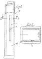
- Magazine 1 is set up for a submachine gun and has a housing made of plastic, which also has a side wall 2 forms.
- a side wall 2 forms.
- In one of these side walls is an elongated, for Longitudinal extension of this side wall is parallel and central Viewing slot 3 introduced into which a plate 4 made of transparent Plastic is used inseparably.
- the plate 4 instructs its peripheral edge on a circumferential groove in which the material the side wall 2 to form a complementary web intervenes.
- This training can be done in a known manner by composite casting getting produced.
- the inner surface of the plate 4 is flush with the surrounding surface the side wall 2. Otherwise, the inner surface has the side wall 2 projections, which the (not shown) Feeder.
- the outer surface of the plate 4 is a little over the Outer surface of the side wall 2 over, but not over the entire Outside outline of magazine 1.
Landscapes
- Engineering & Computer Science (AREA)
- General Engineering & Computer Science (AREA)
- Lead Frames For Integrated Circuits (AREA)
- Discharge Heating (AREA)
- Container, Conveyance, Adherence, Positioning, Of Wafer (AREA)
- Packaging Of Annular Or Rod-Shaped Articles, Wearing Apparel, Cassettes, Or The Like (AREA)
- Toys (AREA)
- Portable Nailing Machines And Staplers (AREA)
- Secondary Cells (AREA)
Abstract
Description
- Fig. 1
- ein erfindungsgemäßes Stangenmagazin für eine Maschinenpistole in Seitenansicht; und
- Fig. 2
- einen Querschnitt längs der Linie II-II in Fig. 1.
Claims (6)
- Stangenmagazin (1), gekennzeichnet durch einen Sichtschlitz (3) in einer Seitenwand (2), der durch eine Platte (4) aus durchsichtigem Material ausgefüllt ist.
- Stangenmagazin (1) nach Anspruch 1, dadurch gekennzeichnet, daß die Innenoberfläche der Platte (4) mit der Innenoberfläche der Seitenwand (2) bündig abschließt.
- Stangenmagazin (1) nach einem der vorstehenden Ansprüche, dadurch gekennzeichnet, daß die Platte (4) an ihrer Umfangskante eine umlaufende Nut oder einen umlaufenden Steg aufweist, und daß das Material der Seitenwand (2) in die Nut eingreift bzw. den Steg umgreift.
- Stangenmagazin (1) nach einem der vorstehenden Ansprüche, dadurch gekennzeichnet, daß die Außenoberfläche der Platte (4) über die Außenoberfläche der Seitenwand (2) übersteht.
- Stangenmagazin (1) nach einem der vorstehenden Ansprüche, dadurch gekennzeichnet, daß es aus undurchsichtigem Kunststoff hergestellt ist.
- Stangenmagazin (1) nach einem der vorstehenden Ansprüche, dadurch gekennzeichnet, daß die Platte (4) aus durchsichtigem Kunststoff hergestellt ist.
Applications Claiming Priority (2)
| Application Number | Priority Date | Filing Date | Title |
|---|---|---|---|
| DE29810423U | 1998-06-10 | ||
| DE29810423U DE29810423U1 (de) | 1998-06-10 | 1998-06-10 | Stangenmagazin |
Publications (3)
| Publication Number | Publication Date |
|---|---|
| EP0964220A2 true EP0964220A2 (de) | 1999-12-15 |
| EP0964220A3 EP0964220A3 (de) | 2000-03-29 |
| EP0964220B1 EP0964220B1 (de) | 2005-12-28 |
Family
ID=8058370
Family Applications (1)
| Application Number | Title | Priority Date | Filing Date |
|---|---|---|---|
| EP99111227A Expired - Lifetime EP0964220B1 (de) | 1998-06-10 | 1999-06-09 | Stangenmagazin |
Country Status (4)
| Country | Link |
|---|---|
| EP (1) | EP0964220B1 (de) |
| AT (1) | ATE314620T1 (de) |
| DE (2) | DE29810423U1 (de) |
| ES (1) | ES2255204T3 (de) |
Cited By (1)
| Publication number | Priority date | Publication date | Assignee | Title |
|---|---|---|---|---|
| CN103471455A (zh) * | 2012-06-08 | 2013-12-25 | 合肥杰事杰新材料股份有限公司 | 一种透明可视弹匣 |
Families Citing this family (1)
| Publication number | Priority date | Publication date | Assignee | Title |
|---|---|---|---|---|
| DE102020000297A1 (de) * | 2020-01-20 | 2021-07-22 | Schmeisser Gmbh | Gehäuse für ein Patronenmagazin für eine Handfeuerwaffe, Patronenmagazin für eine Handfeuerwaffe und Verfahren zum Herstellen eines Gehäuses für ein Patronenmagazin für eine Handfeuerwaffe |
Family Cites Families (11)
| Publication number | Priority date | Publication date | Assignee | Title |
|---|---|---|---|---|
| FR18306E (fr) * | 1914-03-23 | Pierre Dechorin | Indicateur de chargement pour pistolets automatiques | |
| FR394321A (fr) * | 1908-09-15 | 1909-01-20 | Ole Herman Johannes Krag | Pistolet automatique |
| US2828568A (en) * | 1955-06-17 | 1958-04-01 | Edwin G Sakewitz | Cartridge indicating magazine for automatic pistols and other firearms |
| US3143820A (en) * | 1963-06-14 | 1964-08-11 | John J Lucianetti | Rifle magazine assembly |
| DE1934144A1 (de) * | 1969-07-05 | 1971-02-04 | Heckler & Koch Gmbh | Patronengurtkasten fuer Maschinengewehre |
| FR2067098A1 (de) * | 1969-11-03 | 1971-08-20 | France Etat | |
| DE2247698A1 (de) * | 1972-09-28 | 1974-04-04 | Rheinmetall Gmbh | Patronenmagazin fuer handfeuerwaffen, insbesondere automatische gewehre |
| US4109401A (en) * | 1977-08-22 | 1978-08-29 | Daniel Dennis Musgrave | Magazine contents indicators |
| US5206444A (en) * | 1990-11-16 | 1993-04-27 | Oliver Harry M | Device that displays count of rounds in firearm magazines |
| US5149897A (en) * | 1991-12-06 | 1992-09-22 | Howard William J | See-through magazine |
| US5461811A (en) * | 1994-10-24 | 1995-10-31 | Ciener; Jonathan A. | Gun magazine apparatus and method |
-
1998
- 1998-06-10 DE DE29810423U patent/DE29810423U1/de not_active Expired - Lifetime
-
1999
- 1999-06-09 AT AT99111227T patent/ATE314620T1/de not_active IP Right Cessation
- 1999-06-09 ES ES99111227T patent/ES2255204T3/es not_active Expired - Lifetime
- 1999-06-09 DE DE59912969T patent/DE59912969D1/de not_active Expired - Fee Related
- 1999-06-09 EP EP99111227A patent/EP0964220B1/de not_active Expired - Lifetime
Non-Patent Citations (1)
| Title |
|---|
| None |
Cited By (1)
| Publication number | Priority date | Publication date | Assignee | Title |
|---|---|---|---|---|
| CN103471455A (zh) * | 2012-06-08 | 2013-12-25 | 合肥杰事杰新材料股份有限公司 | 一种透明可视弹匣 |
Also Published As
| Publication number | Publication date |
|---|---|
| EP0964220A3 (de) | 2000-03-29 |
| DE59912969D1 (de) | 2006-02-02 |
| ATE314620T1 (de) | 2006-01-15 |
| DE29810423U1 (de) | 1998-09-17 |
| EP0964220B1 (de) | 2005-12-28 |
| ES2255204T3 (es) | 2006-06-16 |
Similar Documents
| Publication | Publication Date | Title |
|---|---|---|
| EP1994355B1 (de) | Kunststoffmagazin | |
| DE102006048436B4 (de) | Zweiwegeabzug mit Druckpunkt | |
| DE102005016020A1 (de) | Schußwaffengriff und Bausatz mit Wechselteilen hierfür | |
| EP3988889B1 (de) | Gehäuse für ein patronenmagazin für eine handfeuerwaffe und patronenmagazin für eine handfeuerwaffe | |
| DE2030228A1 (de) | Automatische Handfeuerwaffe mit auswechselbarem Magazin | |
| DE10353155B4 (de) | Verschlußsperre | |
| DE10353154B3 (de) | Verriegelungshebel und Selbstladewaffe mit diesem Verriegelungshebel | |
| EP1481214A1 (de) | Kunststoffgehäuse mit staubklappe für handfeuerwaffe | |
| DE1728251B2 (de) | Griffstück für eine Selbstladepistole | |
| DE10392248T5 (de) | Schusswaffen-Sicherheitsvorrichtung | |
| DE19507012C2 (de) | Magazinhalter | |
| DE19501397C2 (de) | Munitionstransport in einer Mehrladewaffe | |
| DE102021118639B3 (de) | Verschlussführungs-Vorrichtung einer semiautomatischen oder automatischen Feuerwaffe | |
| DE3609171C2 (de) | Griffanordnung für eine Faustfeuerwaffe | |
| EP0964220B1 (de) | Stangenmagazin | |
| AT507219B1 (de) | Pistole | |
| CH580269A5 (en) | Automatic firearm with magazine in butt - has optional case ejection opening for facilitating aiming during firing (OE150475) | |
| DE102009057864A1 (de) | Handfeuerwaffe | |
| EP0346516A1 (de) | Regal mit Seitenwänden aus mehrlagigem Faltmaterial | |
| DE4426210C2 (de) | Pfandschloß für Transportwagen | |
| DE9012034U1 (de) | Schlüsselanhänger | |
| DE102021111955A1 (de) | Schusswaffe mit austauschbarem Vorderschaft | |
| DE1453923A1 (de) | Automatische Handfeuerwaffe | |
| AT511266B1 (de) | Pistole mit magazinhalterung | |
| AT6054U1 (de) | Handgriff für eine faustfeuerwaffe und teilesatz dafür |
Legal Events
| Date | Code | Title | Description |
|---|---|---|---|
| PUAI | Public reference made under article 153(3) epc to a published international application that has entered the european phase |
Free format text: ORIGINAL CODE: 0009012 |
|
| AK | Designated contracting states |
Kind code of ref document: A2 Designated state(s): AT BE CH DE ES FR GB IT LI |
|
| AX | Request for extension of the european patent |
Free format text: AL;LT;LV;MK;RO;SI |
|
| PUAL | Search report despatched |
Free format text: ORIGINAL CODE: 0009013 |
|
| AK | Designated contracting states |
Kind code of ref document: A3 Designated state(s): AT BE CH CY DE DK ES FI FR GB GR IE IT LI LU MC NL PT SE |
|
| AX | Request for extension of the european patent |
Free format text: AL;LT;LV;MK;RO;SI |
|
| 17P | Request for examination filed |
Effective date: 20000518 |
|
| AKX | Designation fees paid |
Free format text: AT BE CH DE ES FR GB IT LI |
|
| 17Q | First examination report despatched |
Effective date: 20040722 |
|
| GRAP | Despatch of communication of intention to grant a patent |
Free format text: ORIGINAL CODE: EPIDOSNIGR1 |
|
| GRAS | Grant fee paid |
Free format text: ORIGINAL CODE: EPIDOSNIGR3 |
|
| GRAA | (expected) grant |
Free format text: ORIGINAL CODE: 0009210 |
|
| AK | Designated contracting states |
Kind code of ref document: B1 Designated state(s): AT BE CH DE ES FR GB IT LI |
|
| REG | Reference to a national code |
Ref country code: GB Ref legal event code: FG4D Free format text: NOT ENGLISH |
|
| REG | Reference to a national code |
Ref country code: CH Ref legal event code: NV Representative=s name: E. BLUM & CO. PATENTANWAELTE Ref country code: CH Ref legal event code: EP |
|
| REF | Corresponds to: |
Ref document number: 59912969 Country of ref document: DE Date of ref document: 20060202 Kind code of ref document: P |
|
| GBT | Gb: translation of ep patent filed (gb section 77(6)(a)/1977) |
Effective date: 20060322 |
|
| REG | Reference to a national code |
Ref country code: ES Ref legal event code: FG2A Ref document number: 2255204 Country of ref document: ES Kind code of ref document: T3 |
|
| ET | Fr: translation filed | ||
| PLBE | No opposition filed within time limit |
Free format text: ORIGINAL CODE: 0009261 |
|
| STAA | Information on the status of an ep patent application or granted ep patent |
Free format text: STATUS: NO OPPOSITION FILED WITHIN TIME LIMIT |
|
| 26N | No opposition filed |
Effective date: 20060929 |
|
| REG | Reference to a national code |
Ref country code: CH Ref legal event code: PFA Owner name: HECKLER & KOCH GMBH Free format text: HECKLER & KOCH GMBH#ALTE STEIGE 7#78727 OBERNDORF (DE) -TRANSFER TO- HECKLER & KOCH GMBH#ALTE STEIGE 7#78727 OBERNDORF (DE) |
|
| PGFP | Annual fee paid to national office [announced via postgrant information from national office to epo] |
Ref country code: ES Payment date: 20090629 Year of fee payment: 11 |
|
| PGFP | Annual fee paid to national office [announced via postgrant information from national office to epo] |
Ref country code: AT Payment date: 20090622 Year of fee payment: 11 |
|
| PGFP | Annual fee paid to national office [announced via postgrant information from national office to epo] |
Ref country code: BE Payment date: 20090623 Year of fee payment: 11 |
|
| PGFP | Annual fee paid to national office [announced via postgrant information from national office to epo] |
Ref country code: FR Payment date: 20090618 Year of fee payment: 11 Ref country code: CH Payment date: 20090624 Year of fee payment: 11 |
|
| PGFP | Annual fee paid to national office [announced via postgrant information from national office to epo] |
Ref country code: GB Payment date: 20090623 Year of fee payment: 11 Ref country code: DE Payment date: 20090731 Year of fee payment: 11 |
|
| PGFP | Annual fee paid to national office [announced via postgrant information from national office to epo] |
Ref country code: IT Payment date: 20090626 Year of fee payment: 11 |
|
| BERE | Be: lapsed |
Owner name: *HECKLER & KOCH G.M.B.H. Effective date: 20100630 |
|
| REG | Reference to a national code |
Ref country code: CH Ref legal event code: PL |
|
| GBPC | Gb: european patent ceased through non-payment of renewal fee |
Effective date: 20100609 |
|
| REG | Reference to a national code |
Ref country code: FR Ref legal event code: ST Effective date: 20110228 |
|
| PG25 | Lapsed in a contracting state [announced via postgrant information from national office to epo] |
Ref country code: IT Free format text: LAPSE BECAUSE OF NON-PAYMENT OF DUE FEES Effective date: 20100609 |
|
| PG25 | Lapsed in a contracting state [announced via postgrant information from national office to epo] |
Ref country code: LI Free format text: LAPSE BECAUSE OF NON-PAYMENT OF DUE FEES Effective date: 20100630 Ref country code: CH Free format text: LAPSE BECAUSE OF NON-PAYMENT OF DUE FEES Effective date: 20100630 Ref country code: DE Free format text: LAPSE BECAUSE OF NON-PAYMENT OF DUE FEES Effective date: 20110101 |
|
| PG25 | Lapsed in a contracting state [announced via postgrant information from national office to epo] |
Ref country code: AT Free format text: LAPSE BECAUSE OF NON-PAYMENT OF DUE FEES Effective date: 20100609 Ref country code: FR Free format text: LAPSE BECAUSE OF NON-PAYMENT OF DUE FEES Effective date: 20100630 |
|
| PG25 | Lapsed in a contracting state [announced via postgrant information from national office to epo] |
Ref country code: BE Free format text: LAPSE BECAUSE OF NON-PAYMENT OF DUE FEES Effective date: 20100630 |
|
| REG | Reference to a national code |
Ref country code: ES Ref legal event code: FD2A Effective date: 20110715 |
|
| PG25 | Lapsed in a contracting state [announced via postgrant information from national office to epo] |
Ref country code: GB Free format text: LAPSE BECAUSE OF NON-PAYMENT OF DUE FEES Effective date: 20100609 Ref country code: ES Free format text: LAPSE BECAUSE OF NON-PAYMENT OF DUE FEES Effective date: 20110705 |
|
| PG25 | Lapsed in a contracting state [announced via postgrant information from national office to epo] |
Ref country code: ES Free format text: LAPSE BECAUSE OF NON-PAYMENT OF DUE FEES Effective date: 20100610 |