EP0964256A1 - Verfahren und Vorrichtung zur Ortung von Kurzschlüssen in einem Bus eines Multiplexnetzwerks zur Informationsübertragung - Google Patents
Verfahren und Vorrichtung zur Ortung von Kurzschlüssen in einem Bus eines Multiplexnetzwerks zur Informationsübertragung Download PDFInfo
- Publication number
- EP0964256A1 EP0964256A1 EP99401392A EP99401392A EP0964256A1 EP 0964256 A1 EP0964256 A1 EP 0964256A1 EP 99401392 A EP99401392 A EP 99401392A EP 99401392 A EP99401392 A EP 99401392A EP 0964256 A1 EP0964256 A1 EP 0964256A1
- Authority
- EP
- European Patent Office
- Prior art keywords
- bus
- network
- resistance
- wires
- measuring
- Prior art date
- Legal status (The legal status is an assumption and is not a legal conclusion. Google has not performed a legal analysis and makes no representation as to the accuracy of the status listed.)
- Ceased
Links
- 238000000034 method Methods 0.000 title claims abstract description 22
- 230000005540 biological transmission Effects 0.000 title claims description 23
- 238000005259 measurement Methods 0.000 claims abstract description 22
- 238000013500 data storage Methods 0.000 claims description 4
- 230000002452 interceptive effect Effects 0.000 claims description 3
- 238000010586 diagram Methods 0.000 description 6
- 230000004807 localization Effects 0.000 description 3
- 230000015556 catabolic process Effects 0.000 description 2
- 230000007257 malfunction Effects 0.000 description 2
- 238000004364 calculation method Methods 0.000 description 1
- 238000006731 degradation reaction Methods 0.000 description 1
- 238000001514 detection method Methods 0.000 description 1
- 238000003745 diagnosis Methods 0.000 description 1
- 238000013507 mapping Methods 0.000 description 1
Images


Classifications
-
- G—PHYSICS
- G01—MEASURING; TESTING
- G01R—MEASURING ELECTRIC VARIABLES; MEASURING MAGNETIC VARIABLES
- G01R31/00—Arrangements for testing electric properties; Arrangements for locating electric faults; Arrangements for electrical testing characterised by what is being tested not provided for elsewhere
- G01R31/08—Locating faults in cables, transmission lines, or networks
- G01R31/081—Locating faults in cables, transmission lines, or networks according to type of conductors
- G01R31/086—Locating faults in cables, transmission lines, or networks according to type of conductors in power transmission or distribution networks, i.e. with interconnected conductors
Definitions
- the invention relates to a method for locating short circuits in at least one bus of a network of transmission of multiplexed information as well as to a device for diagnosing such a network implementing the method.
- the invention can be applied, for example, to diagnosis of the electronic information transmission network multiplexed with vehicles, in particular automobiles.
- Detection of malfunctions in the network multiplexed electronics of some vehicles is performed by connection to the network of a diagnostic device.
- the different computers with a diagnostic line provide information to the diagnostic device on the breakdowns or malfunction of the components connected to the network.
- the many bundles of wires constituting the electrical network of the vehicle may deteriorate in various places due to, for example, friction against the structure of the vehicle.
- An object of the present invention is to provide a method of locating short circuits in at least one bus of a multiplexed information transmission network overcoming all or part of the disadvantages of the prior art noted above.
- each of the stages of measurement of the ohmic resistance of the bus consists in measuring successively the resistances of a plurality of loops each formed by two bus wires.
- the bus consists of two wires carrying the information, each of the measurement steps of the ohmic resistance of the bus consisting in measuring successively the resistances of the loops formed by the pair of wires carrying information and each wire carrying information in relation to the two polarities of food of the vehicle.
- the steps for measuring the ohmic resistance of the bus are carried out on the so-called line main bus which is connected to the central unit.
- each of the stages of measurement of the ohmic resistance of the bus includes a plurality of successive resistance measurements for each pair of wires.
- Another object of the invention is to propose a device diagnostic of an electronic transmission network multiplexed information implementing the method.
- an electronic information transmission network multiplexed implementing the method comprises means for measuring the ohmic resistance of the wires constituting the bus, data storage and processing means and means for interactive display of information relating to the location of the short circuit (s) in the bus (s) network.
- the storage means and of data processing cooperate with the means display to indicate to the user the location of one at least two ends of the bus to which a measurement resistance must be performed.
- the means for measuring the ohmic resistance of the wires constituting the buses include means for generating an electric current connected in parallel to means for measuring a voltage so as to constitute two measurement terminals to be connected to respectively two wires of the bus.
- the invention relates to the location of short circuits in the bus or buses of an information transmission network multiplex.
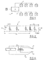
- FIG. 1 schematically shows an example of a such a network 1 for transmitting multiplexed information.
- This network 1 includes two series of computers or C1 stations to Cn and F1 to Fm, which are connected to a central unit 4 at two buses 2, 3 respectively.
- diagnostic 6 is connected to the central unit 4.
- each bus 2, 3 can be made up of two wires carrying information called DATA and DATA .
- Each bus may optionally also have two supply wires conventionally called PLUS and MASS respectively. For the sake of simplification, the two supply wires will not be shown in the figures described below.
- the ohmic resistance of the bus 2, 3 at substantially the two ends of this bus 2, 3. Then, and as described in more detail below, we calculates the distance of the short circuit from one of the bus ends 2, 3 as a function of the resistances measured at the bus ends and known p resistivity values and of total RT resistance of the wires of the bus 2, 3.
- FIG. 2 represents the equivalent diagram of two DATA wires, DATA , of a bus 2 of the network of FIG. 1.
- Four stations having respective impedances Z1, Z2, Z3, Z4 are connected between the two wires DATA and DATA .
- a first type of short circuit is said to be “frank” or “total”, that is to say that the two wires DATA and DATA , are connected by a connection having a zero or negligible short circuit resistance R CC .
- the second type of short circuit is said to be “non-frank” or “partial”, that is to say that the short circuit resistance R CC is not negligible.
- R T the total resistance of the loop formed by the two wires DATA and DATA . This total resistance R T is assumed to be known.
- ⁇ the known resistivity of the DATA wires and DATA from bus 2.
- R BGR and R BDR the resistances measured respectively at the level of the first B1 and second B2 ends of the loop formed by the two wires, assuming in both cases that the short-circuit resistance R CC is zero.
- R BGR R BG - R BG + R Comics - R T 2 .
- a bus being conventionally made up of several wires, to locate a short circuit in this bus according to the invention, we start by measuring the ohmic resistance to both ends of a plurality of loops each formed by two sons of the bus.
- the resistance at the two ends is measured for the four pairs of wires comprising a wire carrying information and a DATA, PLUS supply wire; DATA, MASS; DATA , MORE, DATA , MASS as well as for the DATA wire pair, DATA conveying information.
- FIG. 3 shows an example of a network of multiplexed information transmission.
- This network or bundle has three branches A, B, C.
- Each of the branches A, B, C consists of a bus or main line shown schematically by a pair of wires respectively a11, a12; b11, b12; c11, c12.
- One end of each of the main lines is connected to the central unit 4.
- Three secondary lines a21, a22; b21, b22; c21, c22 are connected respectively to the three main lines a11, at 12; b11, b12; c11, c12.
- each bus or line is shown only by two wires a11, a12; a21, a22.
- a first wire a21 of the secondary line is connected in E1 on the first wire a11 of the main line.
- the second a22 wire the secondary line is connected in E2 to the second wire a12 of the main line.
- L3 P1E1 the distance between the first end A of the main line A and its connection E1 with the first wire a21 of the secondary line.
- L4 P1'E2 the distance between the first end of main line A and its connection E2 with the second a22 secondary line wire.
- the length values L1, L2, L3, L4, L5 and L6 are known by a predefined modeling of the multiplexed network.
- the invention begins with a step 101 of measuring the resistance R BG at a first end A of the main line a11, a12 of the bus.
- the next step 102 is the measurement of the resistance R BD at the second end A 'of this main line.
- the distance D1 or D2 is calculated using the general formula given above.
- the values of the total resistance R T of the main loop and the resistivity ⁇ of its wires are given by the predefined modeling 200 of the network 1.
- this comparison will allow conclude (step 105) that the short circuit is in the vicinity from the end S2S2 'of the secondary line.
- Steps 101, 102 for measuring resistance to bus ends are preferably carried out on the line main a11, a12; b11, b12, c11, c12 of the branch concerned.
- the invention therefore makes it possible to precisely locate a short circuit. "partial” or “total” on the main line a12, a22 of a bus or a “total” short circuit on a sub-branch a21, a22 of this main line.
- a short circuit For “partial” short circuits on a secondary line a21, a22, it was found that the invention allows to determine the secondary line on which finds the anomaly but not for sure its precise position on this secondary line. However, this location of the deteriorated secondary line constitutes information sufficient for a convenience store.
- the function for locating short circuits in bus of a network 1 according to the invention can be integrated into a known device for diagnosing the network 1.
- the diagnostic device will include in addition to functionality usual means 5 for measuring ohmic resistance wires constituting the buses 2, 3 as well as means of data storage and processing. These means of data storage and processing will include modeling at least one type of network to be diagnosed.
- the diagnostic device may also include means (not shown) for interactive display of information relating to the location of short circuits in the bus (s) 2, 3 of network 1.
- an additional step 106 can consist of displaying the result of the localization of the short circuits.
- the means for measuring the resistance of the diagnostic device wires can be consisting of means 10 for generating an electric current which are connected in parallel to means 11 for measuring a voltage so as to constitute two terminals 12, 13 for measuring at connect respectively on two wires of the bus.
- the voltage measurement means 11 can consist of a millivoltmeter digital.
- the diagnostic device which is connected to the diagnostic socket 6 of the vehicle, is used in a known manner to indicate the bus (s) 2, 3 of network 1 who have an anomaly ( Figure 1).
- the convenience store connects successively the terminals 12, 13 for measuring the resistance of the diagnostic device at both ends of the bus concerned.
- the two ends of the bus where one performs the resistance measurement are located on the one hand at the level of the connection of the bus 2, 3 to the central unit 4, and on the other hand to the level of connection of this bus to the most away from the central unit 4.
- the diagnostic device can indicate at the convenience store, via display means, the identity and the location of the computer which is furthest from the unit central 4.
- each of the steps 101, 102 of measuring resistance at one end of the bus can comprise a plurality of successive measurements carried out automatically. That is to say that the resistance at the two ends of each of the five pairs of DATA, PLUS wires is measured several times in succession; DATA, MASS; DATA , MORE; DATA , MASS and DATA, DATA .
- the number of successive measurements at each end can, for example, be equal to five.
- the diagnostic device automatically processes information measured and indicates to the convenience store the location of the short circuit in the network.
- the operator can then dismantle the relevant part of the vehicle to replace the damaged wire (s).
- the means of storage and diagnostic device data processing can contain the models of the multiplexed networks of several types of vehicles. That is, each network modeling will contain precise mapping of the network as well as the values of physical quantities necessary for the calculation step (wire resistivity and total resistance of the latter).
- the resistivity and total resistance values of the wires buses as well as their length will be measured only one times on a standard vehicle network before their storage in the diagnostic device.
Landscapes
- Physics & Mathematics (AREA)
- General Physics & Mathematics (AREA)
- Small-Scale Networks (AREA)
- Locating Faults (AREA)
Applications Claiming Priority (2)
| Application Number | Priority Date | Filing Date | Title |
|---|---|---|---|
| FR9807282 | 1998-06-10 | ||
| FR9807282A FR2779828B1 (fr) | 1998-06-10 | 1998-06-10 | Procede de localisation des courts-circuits dans au moins un bus d'un reseau de transmission d'informations multiplexe et dispositif de diagnostic mettant en oeuvre le procede |
Publications (1)
| Publication Number | Publication Date |
|---|---|
| EP0964256A1 true EP0964256A1 (de) | 1999-12-15 |
Family
ID=9527220
Family Applications (1)
| Application Number | Title | Priority Date | Filing Date |
|---|---|---|---|
| EP99401392A Ceased EP0964256A1 (de) | 1998-06-10 | 1999-06-10 | Verfahren und Vorrichtung zur Ortung von Kurzschlüssen in einem Bus eines Multiplexnetzwerks zur Informationsübertragung |
Country Status (2)
| Country | Link |
|---|---|
| EP (1) | EP0964256A1 (de) |
| FR (1) | FR2779828B1 (de) |
Cited By (7)
| Publication number | Priority date | Publication date | Assignee | Title |
|---|---|---|---|---|
| US6651013B1 (en) | 2000-11-16 | 2003-11-18 | International Business Machines Corporation | Method and apparatus for determining the location of a short in an electrical wire network |
| US7812617B2 (en) * | 2006-07-07 | 2010-10-12 | Sital Technology & Hw Design 1997 Ltd. | System and method for detecting and locating faults in electronic communication bus systems |
| CN103018521A (zh) * | 2011-09-22 | 2013-04-03 | 中兴通讯股份有限公司 | 整流器识别方法及装置 |
| CN104569734A (zh) * | 2013-10-12 | 2015-04-29 | 北京航天计量测试技术研究所 | 一种电缆网冗余线故障诊断方法 |
| CN103018521B (zh) * | 2011-09-22 | 2016-12-14 | 南京中兴新软件有限责任公司 | 整流器识别方法及装置 |
| CN110100418A (zh) * | 2016-12-16 | 2019-08-06 | 标致雪铁龙汽车股份有限公司 | 用于多线束多路复用网络的特定阻抗通信部件 |
| CN119247214A (zh) * | 2024-12-04 | 2025-01-03 | 安徽习承科技有限公司 | 一种基于专变终端接口短路保护测试的数据交互系统 |
Citations (8)
| Publication number | Priority date | Publication date | Assignee | Title |
|---|---|---|---|---|
| EP0327191A2 (de) * | 1988-01-05 | 1989-08-09 | Automated Light Technologies | Mittel zur ohmschen Fehlerortsbestimmung und Vorrichtung für die Verwendung bei Kabeln |
| US4868507A (en) * | 1988-11-23 | 1989-09-19 | Minnesota Mining And Manufacturing Company | Microcomputer controlled resistance fault locator circuit |
| EP0474907A1 (de) * | 1990-09-12 | 1992-03-18 | Fujikura Ltd. | Diagnosegerät für ein Netzwerksystem von Fahrzeugen und Methode zum Untersuchen eines Netzwerksystems von Fahrzeugen |
| EP0681187A2 (de) * | 1994-04-04 | 1995-11-08 | Fluke Corporation | Gerät und Verfahren zur Prüfung der Kabel eines lokalen Netzes |
| EP0716311A2 (de) * | 1994-12-09 | 1996-06-12 | Chrysler Corporation | Apparat und Methode zur Diagnose eines Elektrizitätssystems eines Fahrzeuges |
| EP0784209A2 (de) * | 1996-01-10 | 1997-07-16 | Sumitomo Wiring Systems, Ltd. | Verfahren zur Detektion von Fehlern in Kabelbäumen und Kabelbaum dafür |
| EP0819947A2 (de) * | 1996-06-17 | 1998-01-21 | Norscan Instruments, Ltd. | Ohmsche Fehlerortsbestimmung |
| EP0827872A2 (de) * | 1996-09-09 | 1998-03-11 | Ford Motor Company | Verfahren und System zur Erkennung von Fehlerbedingungen in Multiplexnetzwerken |
-
1998
- 1998-06-10 FR FR9807282A patent/FR2779828B1/fr not_active Expired - Fee Related
-
1999
- 1999-06-10 EP EP99401392A patent/EP0964256A1/de not_active Ceased
Patent Citations (8)
| Publication number | Priority date | Publication date | Assignee | Title |
|---|---|---|---|---|
| EP0327191A2 (de) * | 1988-01-05 | 1989-08-09 | Automated Light Technologies | Mittel zur ohmschen Fehlerortsbestimmung und Vorrichtung für die Verwendung bei Kabeln |
| US4868507A (en) * | 1988-11-23 | 1989-09-19 | Minnesota Mining And Manufacturing Company | Microcomputer controlled resistance fault locator circuit |
| EP0474907A1 (de) * | 1990-09-12 | 1992-03-18 | Fujikura Ltd. | Diagnosegerät für ein Netzwerksystem von Fahrzeugen und Methode zum Untersuchen eines Netzwerksystems von Fahrzeugen |
| EP0681187A2 (de) * | 1994-04-04 | 1995-11-08 | Fluke Corporation | Gerät und Verfahren zur Prüfung der Kabel eines lokalen Netzes |
| EP0716311A2 (de) * | 1994-12-09 | 1996-06-12 | Chrysler Corporation | Apparat und Methode zur Diagnose eines Elektrizitätssystems eines Fahrzeuges |
| EP0784209A2 (de) * | 1996-01-10 | 1997-07-16 | Sumitomo Wiring Systems, Ltd. | Verfahren zur Detektion von Fehlern in Kabelbäumen und Kabelbaum dafür |
| EP0819947A2 (de) * | 1996-06-17 | 1998-01-21 | Norscan Instruments, Ltd. | Ohmsche Fehlerortsbestimmung |
| EP0827872A2 (de) * | 1996-09-09 | 1998-03-11 | Ford Motor Company | Verfahren und System zur Erkennung von Fehlerbedingungen in Multiplexnetzwerken |
Non-Patent Citations (1)
| Title |
|---|
| HIROAKI KOGA ET AL: "STUDY OF FAULT-LOCATION EXPERT SYSTEMS FOR PAIRED CABLES", ELECTRONICS & COMMUNICATIONS IN JAPAN, PART I - COMMUNICATIONS, vol. 74, no. 10, 1 October 1991 (1991-10-01), pages 58 - 66, XP000303554 * |
Cited By (10)
| Publication number | Priority date | Publication date | Assignee | Title |
|---|---|---|---|---|
| US6651013B1 (en) | 2000-11-16 | 2003-11-18 | International Business Machines Corporation | Method and apparatus for determining the location of a short in an electrical wire network |
| US7812617B2 (en) * | 2006-07-07 | 2010-10-12 | Sital Technology & Hw Design 1997 Ltd. | System and method for detecting and locating faults in electronic communication bus systems |
| CN103018521A (zh) * | 2011-09-22 | 2013-04-03 | 中兴通讯股份有限公司 | 整流器识别方法及装置 |
| EP2757383A4 (de) * | 2011-09-22 | 2015-10-14 | Zte Corp | Verfahren und vorrichtung zur identifizierung eines gleichrichters |
| CN103018521B (zh) * | 2011-09-22 | 2016-12-14 | 南京中兴新软件有限责任公司 | 整流器识别方法及装置 |
| EP3499250A1 (de) * | 2011-09-22 | 2019-06-19 | ZTE Corporation | Verfahren und vorrichtung zur identifizierung eines gleichrichters |
| CN104569734A (zh) * | 2013-10-12 | 2015-04-29 | 北京航天计量测试技术研究所 | 一种电缆网冗余线故障诊断方法 |
| CN104569734B (zh) * | 2013-10-12 | 2017-07-18 | 北京航天计量测试技术研究所 | 一种电缆网冗余线故障诊断方法 |
| CN110100418A (zh) * | 2016-12-16 | 2019-08-06 | 标致雪铁龙汽车股份有限公司 | 用于多线束多路复用网络的特定阻抗通信部件 |
| CN119247214A (zh) * | 2024-12-04 | 2025-01-03 | 安徽习承科技有限公司 | 一种基于专变终端接口短路保护测试的数据交互系统 |
Also Published As
| Publication number | Publication date |
|---|---|
| FR2779828B1 (fr) | 2001-04-13 |
| FR2779828A1 (fr) | 1999-12-17 |
Similar Documents
| Publication | Publication Date | Title |
|---|---|---|
| FR3019303B1 (fr) | Dispositif de mesure d'au moins une grandeur physique d'une installation electrique | |
| EP3140666B1 (de) | Verfahren zur erkennung permanenter und intermittierender fehler in einem satz aus zu testenden drähten | |
| EP3262730B1 (de) | Steuerung eines blitzschutzsystems | |
| EP3201641B1 (de) | Verfahren zur erkennung des vorhandenseins eines fehlers, verfahren zur erkennung einer fehlerhaften relaisvorrichtung, verfahren zur erkennung der art von fehler und zugehöriges stromversorgungssystem | |
| WO2014001698A2 (fr) | Surveillance d'un capteur de type transformateur differentiel variable lineaire | |
| EP3259608A1 (de) | Verfahren zur charakterisierung eines unklaren fehlers in einem kabel | |
| EP0964256A1 (de) | Verfahren und Vorrichtung zur Ortung von Kurzschlüssen in einem Bus eines Multiplexnetzwerks zur Informationsübertragung | |
| FR2979994A1 (fr) | Systeme et procede de reflectometrie temporelle pour la localisation non ambigue d'un defaut electrique dans un cable | |
| EP3413064B1 (de) | Elektrische ausrüstung zum anschluss an einen tachometer | |
| EP0454578B1 (de) | Verfahren zum Testen der Zweckmässigkeit der elektromagnetischen Abschirmung eines Leiters und Anordnung dafür | |
| WO2015193626A1 (fr) | Procédé de marquage de faisceaux de lignes électriques pour le diagnostic par réflectométrie et kit correspondant | |
| EP3443365B1 (de) | Vorrichtung zur messung von elektrischen strömen | |
| FR2997508A1 (fr) | Harnais et cable comportant une pluralite de capteurs elementaires et procede de surveillance d'un cable et d'un harnais | |
| EP0866326B1 (de) | Installation zur Aufspürung und Ortung von Flüssigkeitsleckagen | |
| EP2674724B1 (de) | Sensor mit astabilem Output | |
| FR2919070A1 (fr) | Procede de mesure de la continuite electrique d'un cable embarque dans un vehicule. | |
| CA3153911A1 (fr) | Systeme de localisation d'un defaut dans une partie souterraine d'un reseau electrique moyenne tension | |
| WO2023227514A1 (fr) | Bretelle de raccordement, module et procédé de diagnostic de l'état de santé d'une pluralité de câbles électriques | |
| FR3157553A1 (fr) | Procédé et dispositif de détermination de la résistance électrique d’une boucle étalon | |
| FR3067896B1 (fr) | Systeme de raccordement d'elements electriques dans un vehicule automobile | |
| WO2015145059A1 (fr) | Dispositif de blindage électromagnétique de câbles | |
| FR2521296A1 (fr) | Circuit d'alimentation d'une sonde a courants de foucault | |
| FR3136848A1 (fr) | Procédé de codage de conducteurs de communication d’un capteur linéaire appartenant à un système. | |
| FR3022637A1 (fr) | Systeme et methode d'acquisition d'informations resistives retournees par des capteurs | |
| WO2021104712A1 (fr) | Capteur anti-bruit pour vehicule automobile |
Legal Events
| Date | Code | Title | Description |
|---|---|---|---|
| PUAI | Public reference made under article 153(3) epc to a published international application that has entered the european phase |
Free format text: ORIGINAL CODE: 0009012 |
|
| AK | Designated contracting states |
Kind code of ref document: A1 Designated state(s): CH DE ES GB IT LI PT SE |
|
| AX | Request for extension of the european patent |
Free format text: AL;LT;LV;MK;RO;SI |
|
| 17P | Request for examination filed |
Effective date: 20000113 |
|
| AKX | Designation fees paid |
Free format text: CH DE ES GB IT LI PT SE |
|
| 17Q | First examination report despatched |
Effective date: 20080227 |
|
| APBK | Appeal reference recorded |
Free format text: ORIGINAL CODE: EPIDOSNREFNE |
|
| APBN | Date of receipt of notice of appeal recorded |
Free format text: ORIGINAL CODE: EPIDOSNNOA2E |
|
| APBR | Date of receipt of statement of grounds of appeal recorded |
Free format text: ORIGINAL CODE: EPIDOSNNOA3E |
|
| APBV | Interlocutory revision of appeal recorded |
Free format text: ORIGINAL CODE: EPIDOSNIRAPE |
|
| APBK | Appeal reference recorded |
Free format text: ORIGINAL CODE: EPIDOSNREFNE |
|
| APBN | Date of receipt of notice of appeal recorded |
Free format text: ORIGINAL CODE: EPIDOSNNOA2E |
|
| APBR | Date of receipt of statement of grounds of appeal recorded |
Free format text: ORIGINAL CODE: EPIDOSNNOA3E |
|
| APAV | Appeal reference deleted |
Free format text: ORIGINAL CODE: EPIDOSDREFNE |
|
| APAM | Information on closure of appeal procedure modified |
Free format text: ORIGINAL CODE: EPIDOSCNOA9E |
|
| APBB | Information on closure of appeal procedure deleted |
Free format text: ORIGINAL CODE: EPIDOSDNOA9E |
|
| APBT | Appeal procedure closed |
Free format text: ORIGINAL CODE: EPIDOSNNOA9E |
|
| STAA | Information on the status of an ep patent application or granted ep patent |
Free format text: STATUS: THE APPLICATION HAS BEEN REFUSED |
|
| 18R | Application refused |
Effective date: 20120404 |