EP0964502A2 - Générateur de bord entrainé par vibrations ou par air comprimé - Google Patents
Générateur de bord entrainé par vibrations ou par air comprimé Download PDFInfo
- Publication number
- EP0964502A2 EP0964502A2 EP99103965A EP99103965A EP0964502A2 EP 0964502 A2 EP0964502 A2 EP 0964502A2 EP 99103965 A EP99103965 A EP 99103965A EP 99103965 A EP99103965 A EP 99103965A EP 0964502 A2 EP0964502 A2 EP 0964502A2
- Authority
- EP
- European Patent Office
- Prior art keywords
- magnetic piston
- fluid communication
- chamber
- elongated
- cylindrically shaped
- Prior art date
- Legal status (The legal status is an assumption and is not a legal conclusion. Google has not performed a legal analysis and makes no representation as to the accuracy of the status listed.)
- Withdrawn
Links
Images


Classifications
-
- H—ELECTRICITY
- H02—GENERATION; CONVERSION OR DISTRIBUTION OF ELECTRIC POWER
- H02K—DYNAMO-ELECTRIC MACHINES
- H02K7/00—Arrangements for handling mechanical energy structurally associated with dynamo-electric machines, e.g. structural association with mechanical driving motors or auxiliary dynamo-electric machines
- H02K7/18—Structural association of electric generators with mechanical driving motors, e.g. with turbines
- H02K7/1869—Linear generators; sectional generators
- H02K7/1876—Linear generators; sectional generators with reciprocating, linearly oscillating or vibrating parts
- H02K7/1884—Linear generators; sectional generators with reciprocating, linearly oscillating or vibrating parts structurally associated with free piston engines
Definitions
- This invention relates, in general, to pneumatically powered generators and to vibration powered generators and, more particularly, this invention relates to an on-board electrical power generator operated by vibration or compressed air for use on railway vehicles.
- Pneumatic air brakes have been in use for more than 100 years and have been an extremely reliable system.
- electronic controls have been incorporated in the air brake system. The introduction of electronic controls increases the precision of the braking system while maintaining the strength, reliability and efficiency of pneumatic power.
- ECP systems call for a battery system trickle charged by a power source from a front end locomotive. This method requires installation and maintenance of a cable line on each car. In addition to the connection of the brake hoses, the cables must be connected when cars are linked to form a train. In a typical railroad environment, the connectors used must be protected from damage and corrosion.
- this invention provides an electric power generator for use on a railway vehicle.
- the generator comprises a housing member with a magnetic piston that is axially disposed within the housing.
- Such magnetic piston has a first end and a second end each having a rodlike member extending outwardly substantially from a midpoint of a longitudinal axis extending through the magnetic piston.
- Such first and second rod like members on such first end and such second end of such magnetic piston have a first predetermined diameter and a second predetermined diameter, respectively.
- the generator further includes a first diaphragm disposed in the housing member.
- the first diaphragm having a first central opening with a third predetermined diameter, engages the first end of the magnetic piston with the first rodlike member of the magnetic piston extending through the first central opening.
- a first cover for the housing member such first cover has a cylindrically shaped and generally hollow projection to accommodate longitudinal movement of the first rodlike member of the magnetic piston and further has a first chamber connected for fluid communication with a first source of fluid pressure. Such first chamber is sealed by the first diaphragm.
- the housing member has a second cover.
- Such second cover has a cylindrically shaped and generally hollow projection to accommodate longitudinal, movement of the second rodlike member of the magnetic piston and further has a second chamber connected for fluid communication with a second source of fluid pressure.
- Such second chamber is sealed by the second diaphragm, wherein fluid pressure in the second chamber is being exhausted when said the first chamber is being pressurized and fluid pressure in the first chamber is being exhausted when the second chamber is being pressurized.
- the generator further includes a first biasing means that is axially disposed within the first chamber. Such first biasing means is caged between the magnetic piston and an inner surface of the first cover. The first biasing means provides a first bias for such magnetic piston.
- a second biasing means is axially disposed within the second chamber, such second biasing means is caged between the magnetic piston and an inner surface of the second cover. Such second biasing means provides a second bias for the magnetic piston.
- the generator further has an electric coil disposed within the housing member. Such electric coil is positioned so as to encircle at least a predetermined portion of the magnetic piston whereby movement of the magnetic piston creates a voltage across the coil and thereby generating electric power.
- the present invention provides an on-board electrical power generation system for generating electrical power on a railway freight vehicle, such electrical power generation system comprises a generator unit, a control valve, and a switching mechanism.
- the generator unit is described supra.
- a piston type control valve is connected to a source of fluid pressure and is further in fluid communication with such first chamber in the first end and such second chamber in the second end of the generator unit.
- the piston type control valve communicates fluid pressure alternately to such first chamber and such second chamber of the generator unit causing such magnetic piston to oscillate by fluid pressure between such first diaphragm and first biasing means and such second diaphragm and second biasing means thereby generating an electrical voltage across the coil.
- a switching means controls such fluid pressure supply to the control valve, such switching means opens to communicate fluid pressure to such control valve when such railway car is not moving thereby causing the magnetic piston to oscillate by fluid pressure and closes to restrict the flow of fluid pressure to such control valve when such railway car is moving thereby permitting the magnetic piston to oscillate between such first diaphragm and biasing means and such second diaphragm and biasing means by means of vehicle vibration.
- An additional object of the present invention is to provide an on-board electrical power generation system with a switching means for controlling the mode of operation from vibration to fluid pressure.
- a further object of the present invention is to provide an on-board electrical power generation system with a sensing means that can control the switching mechanism automatically.
- Yet another object of the present invention is to provide an on-board electrical power generation system that is adaptive to changes in vehicle vibration conditions due to changes in load conditions on the railway car.
- Still another object of the present invention is to provide an on-board electrical power generation system that is adaptive to changes in weather or track conditions.
- the generator 20 comprises a housing member 9 having a bore disposed along a longitudinal axis thereof.
- the magnetic piston 1 has a first end 2 and a second end 8.
- Such first end 2 will be also be referred to as a top end 2, while such second end 8 will also be referred to as bottom end 8.
- the magnetic piston further has a first rodlike member 14 extending outwardly from such first end 2 and a second rodlike member 22 extending outwardly from said second end 8, rodlike members 14 and 22 extend outwardly substantially from a midpoint of a longitudinal axis extending through magnetic piston 1.
- Such rodlike members 14 and 22 have a first predetermined diameter and a second predetermined diameter, respectively.
- a first diaphragm member 3 is disposed in housing 9.
- the first diaphragm member 3 has a first central opening with a third predetermined diameter.
- Such first diaphragm member 3 engages the first end 2 of magnetic piston 1 with such first rodlike member 14 of the magnetic piston 1 extending through the first central opening.
- the first cover 11 has a cylindrically shaped and generally hollow projection which accommodates longitudinal movement of such first rodlike member 14 of magnetic piston 1.
- the first cover 11 has a first chamber 16 which is connected for fluid communication with a first source of fluid pressure, first chamber 16 being sealed by first diaphragm 3.
- the second diaphragm member 5 has a second central opening with a fourth predetermined diameter and engages second end 8 of magnetic piston 1 and having second rodlike member 22 extending through such second central opening.
- a second cover 12 for housing member 9 has a cylindrically shaped and generally hollow projection which accommodates longitudinal movement of such second rodlike member 22 of magnetic piston 1.
- the second cover 12 has a second chamber 18 connectable with a second source of fluid pressure.
- the second chamber 18 is sealed by second diaphragm 5.
- Such fluid pressure in second chamber 18 is being exhausted when such fluid pressure in the first chamber 16 is being pressurized and fluid pressure in such first chamber 16 is being exhausted when fluid pressure in such second chamber 18 is being pressurized.
- the difference in fluid pressure between the first chamber 16 and second chamber 18 causes the magnetic piston 1 to move from one end to the other depending upon which chamber is being pressurized. This sequence is then reversed and repeated causing magnetic piston 1 to oscillate between such first end and such second end of housing member 1.
- Generator 20 has a first biasing means 4 axially disposed within first chamber 16.
- the first biasing means 4 is disposed around the first rodlike member 14, which extends outwardly from first end 2 of magnetic piston 1, and is caged between first diaphragm member 3 and an inner surface of first cover 11.
- Such first biasing means 4 provides a first bias for the magnetic piston 1.
- second biasing means 6 axially disposed within second chamber 18.
- second biasing means 6 is disposed around the second rodlike member 22, which extends outwardly from the second end 8 of the magnetic piston 1, and is caged between second diaphragm 5 and an inner surface of second cover 12.
- Second biasing means 6 further provides a second bias for magnetic piston 1.
- such first biasing means is a spring and such second biasing means is a spring.
- the generator 20 further includes an electric coil 7 which is disposed within housing 9 and positioned so as to encircle at least a predetermined portion of said magnetic piston 1 whereby movement of said magnetic piston 1 creates a voltage across said electric coil 7 and thereby generating such electrical power.
- rodlike members 14 and 22 which extend outwardly from the ends of the magnetic piston 1 and the cylindrically shaped and generally hollow projections on the first cover 11 and second cover 12 maintain the position of the magnetic piston 1 in the housing 9 and prevent the magnetic piston 1 from moving in a lateral direction.
- One of the main features of generator 20 is the magnetic piston 1 which is engaged by first diaphragm 3 and first biasing means 4 combination on the first end 2 of the magnetic piston 1 and a second diaphragm 5 and second biasing means 6 combination on the second end 8 of the magnetic piston 1.
- This arrangement creates a mass-spring system, which can vibrate under external excitation.
- the vibration which results from vehicle movement, allows magnetic piston 1 to oscillate and interact with electric coil 7 and thereby generate an electrical voltage across the coil 7 as a result of the vehicle vibration.
- the diaphragms in the diaphragm-biasing means combinations create a sealed first chamber 16 between diaphragm 3 and first cover 11 and a sealed second chamber 18 formed by diaphragm 5 and second cover 12.
- the sealed chambers with the diaphragm-biasing means combinations permits the magnetic piston 1 to be operated by fluid pressure. In a preferred embodiment of the invention such fluid pressure is compressed air.
- a control valve may be used to create a fluid pressure that alternates between the first chamber 16 and the second chamber 18 and thereby enable the magnetic piston 1 to oscillate by fluid pressure.
- generator 20 can operate by fluid pressure and a voltage can be created while the railroad car is not moving. Such voltage can also be created by fluid pressure while the car is moving, if desired.
- first and second chambers 16 and 18, respectively are restricted, the chambers will work like air springs. Therefore, exercising controls on the restrictions will allow the generator to adapt to variations in the vibration conditions of the railway vehicle where the generator is mounted. These conditions include changes in the magnitude and frequency of vibration, which could result from changes in vehicle load or speed as well as other changes which could be the result of changes in weather or track conditions.
- the generator 20 is disposed such that the magnetic piston 1 is positioned in a generally vertical direction with the diaphragm and biasing means on both the first end and the second end of the magnetic piston 1. It is preferred that the axis of the piston be such that the piston is made to oscillate in a generally vertical direction because this proivides the best mode for operation by means of vehicle vibration.
- the magnetic piston 1 can operate efficiently in the fluid pressure mode with the piston disposed in any direction but it operates more efficiently in the vibration mode if the magnetic piston 1 is disposed in a generally vertical direction.
- Control valve 30 has an elongated housing member 19 having a predetermined shape.
- Such housing member 19 has a cylindrically shaped bore formed through said housing member 19 from a first end thereof to a second end thereof and along a longitudinal axis thereof.
- inlet port 21 formed through a side wall of housing member 19 closely adjacent a first end thereof, inlet port 21 being adapted to be connected to a source of fluid pressure (not shown) and in fluid communication with such cylindrically shaped bore of housing member 19.
- exhaust port 23 formed through such side wall of the housing member 19. Exhaust port 23 is substantially radially opposed to inlet port 21 and is in fluid communication between such cylindrically shaped bore and atmosphere.
- Such control valve 30 has an elongated cylindrically shaped bushing 29, having an elongated cylindrically shaped bore disposed within the cylindrically shaped bushing 29.
- Such elongated cylindrically shaped bushing 29 is disposed along the longitudinal axis of housing member 19.
- Such control housing 30 further has a first elongated and arcuately shaped fluid communication passageway 38 having a first predetermined length and a first predetermined depth formed in at least one of an inner surface of said housing member 19 and an outer surface of elongated cylindrically shaped bushing 29. First elongated and arcuately shaped fluid communication passageway 38 being disposed in fluid communication with inlet port 21.
- a second elongated and arcuately shaped fluid communication passageway 39 having a second predetermined length and a second predetermined depth is formed in at least one of an inner surface of housing member 19 and an outer surface of elongated cylindrically shaped bushing 29, such second elongated and arcuately shaped fluid communication passageway 39 being disposed in fluid communication with exhaust port 23.
- Such control valve 30 has a third elongated and arcuately shaped fluid communication passageway 41 having a third predetermined length and a third predetermined depth formed in at least one of an inner surface of housing member 19 and an outer surface of elongated cylindrically shaped bushing 29.
- Such third fluid communication passageway 41 is disposed at a point beginning closely adjacent the first end of housing member 19 and a first end of bushing 29.
- a fourth elongated and arcuately shaped fluid communication passageway 43 having a fourth predetermined length and a fourth predetermined depth is also formed in at least one of inner surface of housing member 19 and an outer surface of bushing 29.
- Such fourth fluid communication passageway 43 is disposed at a point beginning closely adjacent the second end of the housing member 19 and a second end of bushing 29.
- such passageways 41 and 43 begin at points substantially identical from such first end and such second end of bushing 29, respectively. It is also preferred that such third and such fourth predetermined lengths of passageways 41 and 43, respectively, be substantially identical.
- first aperture A having a first predetermined configuration formed through a sidewall of said elongated cylindrically shaped bushing substantially at a midpoint thereof.
- First aperture A is in fluid communication with first fluid communication passageway 38 and with such cylindrical bore of bushing 29.
- a second aperture B' having a second predetermined configuration is formed through a sidewall of bushing 29.
- Aperture B' is substantially radially opposed to first aperture A and is disposed closely adjacent a first end of bushing 29.
- Second aperture B' is in fluid communication with the bore of bushing 29 and with second fluid communication passageway 39.
- a third aperture B having a third predetermined configuration is formed through a sidewall of bushing 29.
- Third aperture B is substantially radially opposed to first aperture A and is disposed closely adjacent a second end of bushing 29.
- Third aperture B is in fluid communication with the cylindrically shaped bore of bushing 29 and with second fluid communication passageway 39.
- chat apertures B and B' are positioned the same distance from the second end and the first end of the bushing 29, respectively. Although they are described as being closely adjacent the first and second ends of bushing 29, their exact position is determined by the dimension of piston 33 and that function will be discussed later.
- a fourth aperture C' having a fourth predetermined configuration formed through a sidewall of bushing 19 disposed at a second end of the third fluid communication passageway 41.
- Such fourth aperture C' is in fluid communication with the bore of bushing 29 and with the third fluid communication passageway 41.
- Such control valve 30 further has a fifth aperture D' having a fifth predetermined configuration formed through a sidewall of bushing 29 and disposed at the point beginning closely adjacent the first end of bushing 29 of third fluid communication passageway 41.
- Fifth aperture D' is in fluid communication with the cylindrically shaped bore of bushing 29 and with third fluid communication passageway 41.
- sixth aperture C having a sixth predetermined configuration formed through a sidewall of bushing 29 and disposed at a second end of the fourth fluid communication passageway 43.
- Sixth aperture C is in fluid communication with the cylindrically shaped bore of bushing 29 and with fourth fluid communication passageway 43.
- a seventh aperture D having a seventh predetermined configuration formed through a sidewall of the bushing 29 and disposed at the beginning point, closely adjacent second end of bushing 29, of said fourth fluid communication passageway 43. Seventh aperture D is in fluid communication with the cylindrically shaped bore of bushing 29 and with fourth fluid communication passageway 43.
- apertures C and C' be positioned substantially an equal distance, but in opposite directions, from a midpoint of bushing 29. It is also preferred that D' and D be positioned substantially an equal distance from such first end and such second end of bushing 29.
- Control valve 30 has a piston 33 having a fifth predetermined length disposed for reciprocal movement within the cylindrically shaped bore of bushing 29 along a longitudinal axis thereof.
- Piston 33 has a center portion having a sixth predetermined length, such center portion having a reduced diameter forms a first chamber 45 between such center portion of the piston having a reduced diameter and with the cylindrically shaped bore of bushing 29.
- First chamber 45 of piston 33 is in fluid communication with first aperture A and one of fourth aperture C' and sixth aperture C. Such first chamber 45 can only be in fluid communication with fourth aperture C' or sixth aperture C at one time. If the piston 33 is moved such that first chamber 45 is in fluid communication with C' then C is sealed by the full diameter of piston 33. The reverse is true if first chamber 45 is in fluid communication with aperture C then aperture C' is sealed by the piston 33.
- a first cover 24 is secured to the first end of housing member 19. There is a first outlet port 25 formed through first cover 24. First outlet port 25 is in fluid communication with the cylindrically shaped bore of bushing 29.
- a second cover 26 is secured to the second end of housing member 19.
- a second outlet port 27 is formed through the second cover 26.
- Second outlet port 27 is in fluid communication with the cylindrically shaped bore of bushing 29.
- first cushion 34 positioned inside such first cover 24 and a second cushion 35 positioned inside such second cover 26.
- first cushion 34 and second cushion 35 are used to prevent contact between the ends of piston 33 and such first and second covers, 24 and 26, respectively.
- first cushion 34 has an eighth aperture in fluid communication with the cylindrically shaped bore of bushing 29 and with the first outlet port 25 in first cover 24 while second cushion 35 has a ninth aperture in fluid communication with the cylindrically shaped bore of the bushing 29 and with the second outlet port 27 in second cover 26.
- control valve 30 In the operation of the control valve 30 such fluid pressure from an external source enters control valve 30 through the inlet port 21. Fluid pressure is then communicated along the first fluid communication passageway 38 and through first aperture A into the first chamber 45. Such fluid pressure is then communicated through one of such fourth aperture C' and such sixth aperture C. In the position in which piston 33 is shown in Figure 2 such fluid pressure is communicated to aperture C' while aperture C is sealed by the full diameter of piston 33. Fluid pressure passes through C' along third fluid communication passageway 41 to such fifth aperture D', where such fluid pressure returns to the cylindrically shaped bore of bushing 29. Such fluid pressure now exits from first outlet port 25.
- Fluid pressure also builds up behind the end of piston 33 near first outlet port 25 forcing piston 33 away from such first end of housing member 19 toward the opposite end of housing member 19. Piston 33 will move in that direction until piston 33 has moved a distance sufficient for the end of piston 33 to uncover second aperture B' which opens the fluid pressure behind piston 33 to exhaust port 23 through the second fluid passageway 39. Aperture B is sealed by the other end of piston 33.
- apertures B and B' were described as being closely adjacent first and second ends of bushing 29, the positioning of apertures B and B' from the respective ends of bushing 19 is such that the piston 33 must move a sufficient distance so that aperture C' is closed and aperture C is exposed when the piston 33 clears aperture B' and permits fluid pressure to exhaust.
- Aperture B is positioned in a similar manner in that the piston 33 must move sufficiently so that aperture C' is open and aperture C is closed when the piston clears B and permits fluid pressure to exhaust.
- Apertures B and B' provide a means for fluid communication from opposite ends of the interior of bushing 29 to exhaust port 23 through the annular path.
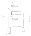
- FIG. 10 Illustrated therein is a schematic representation of one embodiment of an on-board electrical generation system, generally designated 10.
- the generator unit 20 described in detail previously, can be operated by vibration or fluid pressure.
- a switching means is used to control the flow of fluid pressure to piston control valve 30.
- such switching means is a solenoid valve 36.
- solenoid valve 36 is used to control the flow of fluid pressure to such piston control valve 30.
- Solenoid valve 36 is normally closed which is a de-energized position. In this position no fluid pressure communicates with piston control valve 30 and generator 20.
- the input to control valve 30 is open to atmosphere. Under this condition the generator 20 operates in a vibration mode and relies on vehicle vibration to cause the magnetic piston to oscillate between the diaphragm and biasing means combinations to generate electrical voltage across the coil.
- solenoid valve 36 When the railway car is stopped, solenoid valve 36 is energized and fluid pressure is communicated to the piston control valve 30 and hence with generator 20. In this mode, generator 20 operates by fluid pressure. In a preferred embodiment of the invention such fluid pressure is air pressure from a brake line of the railway car.
- a second switching means, solenoid valve 37, may be used in the on-board electrical power generation system 10 to make the system more responsive to variations in vehicle vibration conditions due to changes in load or speed, or changes in weather and track conditions.
- the second solenoid valve 37 is adaptive to empty/load conditions. In a de-energized position such valve 37 has unrestricted exhaust. This position is used where the valve would normally be set for operation in either the fluid pressure mode or in the normal vibration mode. This mode would be used for full railroad cars. However, if the railway car is empty solenoid valve 37 switches to an energized position. In this energized position such solenoid valve 37 opens to a restricted exhaust.
- sensing means are used to control such solenoid valves 36 and 37 so that the operation of the system is automatic.
Landscapes
- Engineering & Computer Science (AREA)
- Power Engineering (AREA)
- Actuator (AREA)
- Braking Systems And Boosters (AREA)
- Vibration Prevention Devices (AREA)
Applications Claiming Priority (2)
| Application Number | Priority Date | Filing Date | Title |
|---|---|---|---|
| US09/095,082 US5945749A (en) | 1998-06-10 | 1998-06-10 | On-board electrical power generator operated by vibration or compressed air |
| US95082 | 1998-06-10 |
Publications (2)
| Publication Number | Publication Date |
|---|---|
| EP0964502A2 true EP0964502A2 (fr) | 1999-12-15 |
| EP0964502A3 EP0964502A3 (fr) | 2003-02-26 |
Family
ID=22249401
Family Applications (1)
| Application Number | Title | Priority Date | Filing Date |
|---|---|---|---|
| EP99103965A Withdrawn EP0964502A3 (fr) | 1998-06-10 | 1999-03-09 | Générateur de bord entrainé par vibrations ou par air comprimé |
Country Status (4)
| Country | Link |
|---|---|
| US (1) | US5945749A (fr) |
| EP (1) | EP0964502A3 (fr) |
| AU (1) | AU753779B2 (fr) |
| CA (1) | CA2246831C (fr) |
Cited By (3)
| Publication number | Priority date | Publication date | Assignee | Title |
|---|---|---|---|---|
| KR100496621B1 (ko) * | 2001-04-20 | 2005-06-20 | 세이코 엡슨 가부시키가이샤 | 진동 에너지의 전력 변환 장치 |
| CN102182775A (zh) * | 2011-04-15 | 2011-09-14 | 清华大学 | 用于汽车分布式电子液压制动系统的制动执行机构 |
| CN105141179A (zh) * | 2015-09-02 | 2015-12-09 | 北京印刷学院 | 轴对称弹簧阻尼共振储能压电变换城市地铁列车减震发电装置 |
Families Citing this family (34)
| Publication number | Priority date | Publication date | Assignee | Title |
|---|---|---|---|---|
| US6628019B2 (en) * | 1999-07-21 | 2003-09-30 | Westinghouse Air Brake Technologies Corporation | High efficiency pneumatically driven electric power generator |
| US7357197B2 (en) * | 2000-11-07 | 2008-04-15 | Halliburton Energy Services, Inc. | Method and apparatus for monitoring the condition of a downhole drill bit, and communicating the condition to the surface |
| US7035773B2 (en) * | 2002-03-06 | 2006-04-25 | Fisher-Rosemount Systems, Inc. | Appendable system and devices for data acquisition, analysis and control |
| US6853103B2 (en) * | 2003-01-31 | 2005-02-08 | Hiro Moriyasu | Low profile push-pull magnetic vibrating apparatus |
| DE10311567B3 (de) * | 2003-03-10 | 2004-11-18 | Siemens Ag | Seismischer Generator und Fahrzeug mit einem seismischen Generator |
| US6914351B2 (en) | 2003-07-02 | 2005-07-05 | Tiax Llc | Linear electrical machine for electric power generation or motive drive |
| DE10358764A1 (de) * | 2003-12-12 | 2005-07-28 | Zf Friedrichshafen Ag | Fahrwerkbauteil |
| ITTO20040054A1 (it) * | 2004-02-04 | 2004-05-04 | Fiat Ricerche | Architetture innovative di sistemi di generazione e distribuzione di energia a bordo di autoveicoli |
| US6856113B1 (en) | 2004-05-12 | 2005-02-15 | Cube Investments Limited | Central vacuum cleaning system motor control circuit mounting post, mounting configuration, and mounting methods |
| US20060081291A1 (en) * | 2004-09-09 | 2006-04-20 | Cube Investments Limited | Central vacuum cleaner wall valve, hose nipple, and cleaning system |
| EP1799087A4 (fr) | 2004-09-17 | 2009-08-12 | Cube Invest Ltd | Poignee d'un dispositif de nettoyage et sections boitier de poignee de dispositif de nettoyage |
| KR20060084972A (ko) * | 2005-01-21 | 2006-07-26 | 경상대학교산학협력단 | 새로운 진동발전기 |
| TWM282416U (en) * | 2005-03-08 | 2005-12-01 | Chuan-Sheng Chen | Vibrating power generator |
| US7690075B2 (en) | 2005-10-07 | 2010-04-06 | Cube Investments Limited | Central vacuum cleaner control, unit and system with contaminant sensor |
| CA2562810C (fr) | 2005-10-07 | 2015-12-08 | Cube Investments Limited | Commande de sources d'aspiration multiples d'aspirateur central |
| CA2562804C (fr) | 2005-10-07 | 2014-12-09 | Cube Investments Limited | Commandes croisees d'aspirateur central |
| US7900315B2 (en) | 2005-10-07 | 2011-03-08 | Cube Investments Limited | Integrated central vacuum cleaner suction device and control |
| US8160655B2 (en) | 2008-02-19 | 2012-04-17 | Braden Kroll | Automatic recharging wireless headset |
| USRE47647E1 (en) | 2008-04-26 | 2019-10-15 | Timothy Domes | Pneumatic mechanical power source |
| US8225900B2 (en) * | 2008-04-26 | 2012-07-24 | Domes Timothy J | Pneumatic mechanical power source |
| US8561747B2 (en) * | 2008-04-26 | 2013-10-22 | Timothy Domes | Pneumatic mechanical power source |
| US20100167602A1 (en) * | 2008-12-16 | 2010-07-01 | Vu Thang D | Energy system and boat |
| TWM370072U (en) * | 2009-07-08 | 2009-12-01 | Kun-Ta Lee | Impact generator and impact testing platform |
| US20110221206A1 (en) * | 2010-03-11 | 2011-09-15 | Miro Milinkovic | Linear power generator with a reciprocating piston configuration |
| WO2013009720A2 (fr) | 2011-07-08 | 2013-01-17 | Fastcap Systems Corporation | Dispositif de stockage d'énergie haute température |
| US9558894B2 (en) | 2011-07-08 | 2017-01-31 | Fastcap Systems Corporation | Advanced electrolyte systems and their use in energy storage devices |
| CN108868747A (zh) | 2011-11-03 | 2018-11-23 | 快帽系统公司 | 生产测井仪 |
| FR2984634B1 (fr) * | 2011-12-19 | 2014-11-07 | Univ Pierre Et Marie Curie Paris 6 | Actionneur vitrotactile lineaire miniature |
| CN104405569B (zh) * | 2012-12-05 | 2017-07-28 | 河海大学常州校区 | 波浪能发电装置 |
| US10872737B2 (en) | 2013-10-09 | 2020-12-22 | Fastcap Systems Corporation | Advanced electrolytes for high temperature energy storage device |
| EP3084481B8 (fr) | 2013-12-20 | 2024-01-03 | Fastcap Systems Corporation | Dispositif de telemetrie electromagnetique |
| KR102668693B1 (ko) | 2015-01-27 | 2024-05-27 | 패스트캡 시스템즈 코포레이션 | 넓은 온도 범위 울트라커패시터 |
| EP3549148B1 (fr) | 2016-12-02 | 2025-01-01 | Fastcap Systems Corporation | Electrode composite |
| CN111997693B (zh) * | 2020-08-28 | 2021-09-03 | 东风汽车集团有限公司 | 一种压缩空气动力发电机 |
Family Cites Families (10)
| Publication number | Priority date | Publication date | Assignee | Title |
|---|---|---|---|---|
| GB1316950A (en) * | 1969-06-30 | 1973-05-16 | Univ North Wales | Electric generator |
| US3555314A (en) * | 1969-11-14 | 1971-01-12 | Us Army | Plural reed reciprocating |
| FR2068093A5 (fr) * | 1969-11-27 | 1971-08-20 | Commissariat Energie Atomique | |
| US3766399A (en) * | 1972-10-19 | 1973-10-16 | M Demetrescu | Combustion engine driven generator including spring structure for oscillating the inductor at the mechanical resonant frequency between power strokes |
| US5084630A (en) * | 1989-03-24 | 1992-01-28 | Hossein Azimi | Wave powered apparatus for generating electric power |
| EP0429733B1 (fr) * | 1989-11-17 | 1999-04-28 | Texas Instruments Incorporated | Multiprocesseur avec commutateur à coordonnées entre processeurs et mémoires |
| JPH07145776A (ja) * | 1993-11-22 | 1995-06-06 | Soichiro Aoyanagi | 車体の振動吸収による電力発生の方法 |
| US5696413A (en) * | 1994-10-24 | 1997-12-09 | Aqua Magnetics, Inc. | Reciprocating electric generator |
| GB2311171A (en) * | 1996-03-15 | 1997-09-17 | Keystone Elec Co Ltd | Device for generating electricity from vibrations |
| JPH1066323A (ja) * | 1996-08-26 | 1998-03-06 | Matsushita Electric Ind Co Ltd | 発電装置とこれを備えた電子機器 |
-
1998
- 1998-06-10 US US09/095,082 patent/US5945749A/en not_active Expired - Fee Related
- 1998-09-08 CA CA002246831A patent/CA2246831C/fr not_active Expired - Fee Related
-
1999
- 1999-02-19 AU AU17380/99A patent/AU753779B2/en not_active Ceased
- 1999-03-09 EP EP99103965A patent/EP0964502A3/fr not_active Withdrawn
Cited By (4)
| Publication number | Priority date | Publication date | Assignee | Title |
|---|---|---|---|---|
| KR100496621B1 (ko) * | 2001-04-20 | 2005-06-20 | 세이코 엡슨 가부시키가이샤 | 진동 에너지의 전력 변환 장치 |
| US7009315B2 (en) | 2001-04-20 | 2006-03-07 | Seiko Epson Corporation | Apparatus for converting vibration energy into electric power |
| CN102182775A (zh) * | 2011-04-15 | 2011-09-14 | 清华大学 | 用于汽车分布式电子液压制动系统的制动执行机构 |
| CN105141179A (zh) * | 2015-09-02 | 2015-12-09 | 北京印刷学院 | 轴对称弹簧阻尼共振储能压电变换城市地铁列车减震发电装置 |
Also Published As
| Publication number | Publication date |
|---|---|
| AU753779B2 (en) | 2002-10-31 |
| AU1738099A (en) | 1999-12-23 |
| EP0964502A3 (fr) | 2003-02-26 |
| CA2246831C (fr) | 2001-01-16 |
| US5945749A (en) | 1999-08-31 |
Similar Documents
| Publication | Publication Date | Title |
|---|---|---|
| US5945749A (en) | On-board electrical power generator operated by vibration or compressed air | |
| US4813448A (en) | Control system for vehicle regulation | |
| US6324845B1 (en) | Self contained, supplemental vacuum assist unit for vehicle brake booster | |
| EP1452416A3 (fr) | Module reservoir et assecheur d'air | |
| DE69819933D1 (de) | Vorratsbehältermodul für einem lufttrockner | |
| US20120306218A1 (en) | Managed pneumatic turbine power supply | |
| US6628019B2 (en) | High efficiency pneumatically driven electric power generator | |
| US6302495B1 (en) | Railway car braking system including piezoelectric pilot valve and associated methods | |
| EP0759388A2 (fr) | Electrovanne, modulateur et système de freinage antiblocage incorporant une telle électrovanne | |
| MXPA01002646A (es) | Insertos de valvula de multiple neumatico controlado electricamente. | |
| HK1027914A (en) | On-board electrical power generator operated by vibration or compressed air | |
| MXPA99005337A (en) | Generator of electric energy on board operated, by vibration or by air comprim | |
| RU174063U1 (ru) | Устройство контроля и управления тормозной магистралью поезда | |
| US856010A (en) | Electropneumatic braking device for railway-cars. | |
| RU46983U1 (ru) | Исполнительная часть пневматической тормозной системы пассажирского локомотива | |
| US243417A (en) | Fluid-pressure brake | |
| US2715049A (en) | Safety control apparatus for multiple unit locomotives | |
| US245592A (en) | Combined electric and fluid-pressure mechanism | |
| SU1558746A1 (ru) | Электропневматическа тормозна система | |
| SU1136999A1 (ru) | Устройство дл поддержани посто нного уровн между подрессоренной и неподрессоренной част ми локомотива при пневмоподвешивании | |
| US957227A (en) | Electropneumatic air-brake system. | |
| SU1630936A1 (ru) | Электропневматический клапанный узел противоюзного устройства | |
| US897696A (en) | Air-brake valve. | |
| US1288475A (en) | Antivibration device for automobiles. | |
| SU1620351A1 (ru) | Электровоздухораспределитель тормоза железнодорожного транспортного средства |
Legal Events
| Date | Code | Title | Description |
|---|---|---|---|
| PUAI | Public reference made under article 153(3) epc to a published international application that has entered the european phase |
Free format text: ORIGINAL CODE: 0009012 |
|
| AK | Designated contracting states |
Kind code of ref document: A2 Designated state(s): AT BE CH CY DE DK ES FI FR GB GR IE IT LI LU MC NL PT SE |
|
| AX | Request for extension of the european patent |
Free format text: AL;LT;LV;MK;RO;SI |
|
| RIC1 | Information provided on ipc code assigned before grant |
Free format text: 7H 02K 35/02 A, 7H 02K 7/18 B |
|
| PUAL | Search report despatched |
Free format text: ORIGINAL CODE: 0009013 |
|
| AK | Designated contracting states |
Kind code of ref document: A3 Designated state(s): AT BE CH CY DE DK ES FI FR GB GR IE IT LI LU MC NL PT SE Designated state(s): AT BE CH CY DE DK ES FI FR GB GR IE IT LI LU MC NL PT SE |
|
| AX | Request for extension of the european patent |
Extension state: AL LT LV MK RO SI |
|
| AKX | Designation fees paid | ||
| REG | Reference to a national code |
Ref country code: DE Ref legal event code: 8566 |
|
| STAA | Information on the status of an ep patent application or granted ep patent |
Free format text: STATUS: THE APPLICATION IS DEEMED TO BE WITHDRAWN |
|
| 18D | Application deemed to be withdrawn |
Effective date: 20030827 |
|
| REG | Reference to a national code |
Ref country code: HK Ref legal event code: WD Ref document number: 1027914 Country of ref document: HK |