EP3549148B1 - Electrode composite - Google Patents
Electrode composite Download PDFInfo
- Publication number
- EP3549148B1 EP3549148B1 EP17876365.2A EP17876365A EP3549148B1 EP 3549148 B1 EP3549148 B1 EP 3549148B1 EP 17876365 A EP17876365 A EP 17876365A EP 3549148 B1 EP3549148 B1 EP 3549148B1
- Authority
- EP
- European Patent Office
- Prior art keywords
- carbon nanotubes
- active layer
- layer
- energy storage
- network
- Prior art date
- Legal status (The legal status is an assumption and is not a legal conclusion. Google has not performed a legal analysis and makes no representation as to the accuracy of the status listed.)
- Active
Links
Images



Classifications
-
- H—ELECTRICITY
- H01—ELECTRIC ELEMENTS
- H01G—CAPACITORS; CAPACITORS, RECTIFIERS, DETECTORS, SWITCHING DEVICES, LIGHT-SENSITIVE OR TEMPERATURE-SENSITIVE DEVICES OF THE ELECTROLYTIC TYPE
- H01G11/00—Hybrid capacitors, i.e. capacitors having different positive and negative electrodes; Electric double-layer [EDL] capacitors; Processes for the manufacture thereof or of parts thereof
- H01G11/22—Electrodes
- H01G11/24—Electrodes characterised by structural features of the materials making up or comprised in the electrodes, e.g. form, surface area or porosity; characterised by the structural features of powders or particles used therefor
-
- H—ELECTRICITY
- H01—ELECTRIC ELEMENTS
- H01G—CAPACITORS; CAPACITORS, RECTIFIERS, DETECTORS, SWITCHING DEVICES, LIGHT-SENSITIVE OR TEMPERATURE-SENSITIVE DEVICES OF THE ELECTROLYTIC TYPE
- H01G11/00—Hybrid capacitors, i.e. capacitors having different positive and negative electrodes; Electric double-layer [EDL] capacitors; Processes for the manufacture thereof or of parts thereof
- H01G11/22—Electrodes
- H01G11/26—Electrodes characterised by their structure, e.g. multi-layered, porosity or surface features
- H01G11/28—Electrodes characterised by their structure, e.g. multi-layered, porosity or surface features arranged or disposed on a current collector; Layers or phases between electrodes and current collectors, e.g. adhesives
-
- H—ELECTRICITY
- H01—ELECTRIC ELEMENTS
- H01G—CAPACITORS; CAPACITORS, RECTIFIERS, DETECTORS, SWITCHING DEVICES, LIGHT-SENSITIVE OR TEMPERATURE-SENSITIVE DEVICES OF THE ELECTROLYTIC TYPE
- H01G11/00—Hybrid capacitors, i.e. capacitors having different positive and negative electrodes; Electric double-layer [EDL] capacitors; Processes for the manufacture thereof or of parts thereof
- H01G11/22—Electrodes
- H01G11/30—Electrodes characterised by their material
- H01G11/32—Carbon-based
-
- H—ELECTRICITY
- H01—ELECTRIC ELEMENTS
- H01G—CAPACITORS; CAPACITORS, RECTIFIERS, DETECTORS, SWITCHING DEVICES, LIGHT-SENSITIVE OR TEMPERATURE-SENSITIVE DEVICES OF THE ELECTROLYTIC TYPE
- H01G11/00—Hybrid capacitors, i.e. capacitors having different positive and negative electrodes; Electric double-layer [EDL] capacitors; Processes for the manufacture thereof or of parts thereof
- H01G11/22—Electrodes
- H01G11/30—Electrodes characterised by their material
- H01G11/32—Carbon-based
- H01G11/36—Nanostructures, e.g. nanofibres, nanotubes or fullerenes
-
- H—ELECTRICITY
- H01—ELECTRIC ELEMENTS
- H01G—CAPACITORS; CAPACITORS, RECTIFIERS, DETECTORS, SWITCHING DEVICES, LIGHT-SENSITIVE OR TEMPERATURE-SENSITIVE DEVICES OF THE ELECTROLYTIC TYPE
- H01G11/00—Hybrid capacitors, i.e. capacitors having different positive and negative electrodes; Electric double-layer [EDL] capacitors; Processes for the manufacture thereof or of parts thereof
- H01G11/22—Electrodes
- H01G11/30—Electrodes characterised by their material
- H01G11/32—Carbon-based
- H01G11/38—Carbon pastes or blends; Binders or additives therein
-
- H—ELECTRICITY
- H01—ELECTRIC ELEMENTS
- H01G—CAPACITORS; CAPACITORS, RECTIFIERS, DETECTORS, SWITCHING DEVICES, LIGHT-SENSITIVE OR TEMPERATURE-SENSITIVE DEVICES OF THE ELECTROLYTIC TYPE
- H01G11/00—Hybrid capacitors, i.e. capacitors having different positive and negative electrodes; Electric double-layer [EDL] capacitors; Processes for the manufacture thereof or of parts thereof
- H01G11/66—Current collectors
- H01G11/70—Current collectors characterised by their structure
-
- H—ELECTRICITY
- H01—ELECTRIC ELEMENTS
- H01G—CAPACITORS; CAPACITORS, RECTIFIERS, DETECTORS, SWITCHING DEVICES, LIGHT-SENSITIVE OR TEMPERATURE-SENSITIVE DEVICES OF THE ELECTROLYTIC TYPE
- H01G11/00—Hybrid capacitors, i.e. capacitors having different positive and negative electrodes; Electric double-layer [EDL] capacitors; Processes for the manufacture thereof or of parts thereof
- H01G11/84—Processes for the manufacture of hybrid or EDL capacitors, or components thereof
- H01G11/86—Processes for the manufacture of hybrid or EDL capacitors, or components thereof specially adapted for electrodes
-
- H—ELECTRICITY
- H01—ELECTRIC ELEMENTS
- H01M—PROCESSES OR MEANS, e.g. BATTERIES, FOR THE DIRECT CONVERSION OF CHEMICAL ENERGY INTO ELECTRICAL ENERGY
- H01M4/00—Electrodes
- H01M4/02—Electrodes composed of, or comprising, active material
- H01M4/64—Carriers or collectors
-
- H—ELECTRICITY
- H01—ELECTRIC ELEMENTS
- H01G—CAPACITORS; CAPACITORS, RECTIFIERS, DETECTORS, SWITCHING DEVICES, LIGHT-SENSITIVE OR TEMPERATURE-SENSITIVE DEVICES OF THE ELECTROLYTIC TYPE
- H01G11/00—Hybrid capacitors, i.e. capacitors having different positive and negative electrodes; Electric double-layer [EDL] capacitors; Processes for the manufacture thereof or of parts thereof
- H01G11/22—Electrodes
- H01G11/26—Electrodes characterised by their structure, e.g. multi-layered, porosity or surface features
-
- H—ELECTRICITY
- H01—ELECTRIC ELEMENTS
- H01M—PROCESSES OR MEANS, e.g. BATTERIES, FOR THE DIRECT CONVERSION OF CHEMICAL ENERGY INTO ELECTRICAL ENERGY
- H01M4/00—Electrodes
- H01M4/02—Electrodes composed of, or comprising, active material
- H01M4/04—Processes of manufacture in general
- H01M4/043—Processes of manufacture in general involving compressing or compaction
-
- H—ELECTRICITY
- H01—ELECTRIC ELEMENTS
- H01M—PROCESSES OR MEANS, e.g. BATTERIES, FOR THE DIRECT CONVERSION OF CHEMICAL ENERGY INTO ELECTRICAL ENERGY
- H01M4/00—Electrodes
- H01M4/02—Electrodes composed of, or comprising, active material
- H01M4/04—Processes of manufacture in general
- H01M4/0471—Processes of manufacture in general involving thermal treatment, e.g. firing, sintering, backing particulate active material, thermal decomposition, pyrolysis
-
- H—ELECTRICITY
- H01—ELECTRIC ELEMENTS
- H01M—PROCESSES OR MEANS, e.g. BATTERIES, FOR THE DIRECT CONVERSION OF CHEMICAL ENERGY INTO ELECTRICAL ENERGY
- H01M4/00—Electrodes
- H01M4/02—Electrodes composed of, or comprising, active material
- H01M4/13—Electrodes for accumulators with non-aqueous electrolyte, e.g. for lithium-accumulators; Processes of manufacture thereof
- H01M4/133—Electrodes based on carbonaceous material, e.g. graphite-intercalation compounds or CFx
-
- H—ELECTRICITY
- H01—ELECTRIC ELEMENTS
- H01M—PROCESSES OR MEANS, e.g. BATTERIES, FOR THE DIRECT CONVERSION OF CHEMICAL ENERGY INTO ELECTRICAL ENERGY
- H01M4/00—Electrodes
- H01M4/02—Electrodes composed of, or comprising, active material
- H01M4/36—Selection of substances as active materials, active masses, active liquids
- H01M4/58—Selection of substances as active materials, active masses, active liquids of inorganic compounds other than oxides or hydroxides, e.g. sulfides, selenides, tellurides, halogenides or LiCoFy; of polyanionic structures, e.g. phosphates, silicates or borates
- H01M4/583—Carbonaceous material, e.g. graphite-intercalation compounds or CFx
-
- H—ELECTRICITY
- H01—ELECTRIC ELEMENTS
- H01M—PROCESSES OR MEANS, e.g. BATTERIES, FOR THE DIRECT CONVERSION OF CHEMICAL ENERGY INTO ELECTRICAL ENERGY
- H01M4/00—Electrodes
- H01M4/02—Electrodes composed of, or comprising, active material
- H01M4/62—Selection of inactive substances as ingredients for active masses, e.g. binders, fillers
- H01M4/624—Electric conductive fillers
- H01M4/625—Carbon or graphite
-
- Y—GENERAL TAGGING OF NEW TECHNOLOGICAL DEVELOPMENTS; GENERAL TAGGING OF CROSS-SECTIONAL TECHNOLOGIES SPANNING OVER SEVERAL SECTIONS OF THE IPC; TECHNICAL SUBJECTS COVERED BY FORMER USPC CROSS-REFERENCE ART COLLECTIONS [XRACs] AND DIGESTS
- Y02—TECHNOLOGIES OR APPLICATIONS FOR MITIGATION OR ADAPTATION AGAINST CLIMATE CHANGE
- Y02E—REDUCTION OF GREENHOUSE GAS [GHG] EMISSIONS, RELATED TO ENERGY GENERATION, TRANSMISSION OR DISTRIBUTION
- Y02E60/00—Enabling technologies; Technologies with a potential or indirect contribution to GHG emissions mitigation
- Y02E60/10—Energy storage using batteries
-
- Y—GENERAL TAGGING OF NEW TECHNOLOGICAL DEVELOPMENTS; GENERAL TAGGING OF CROSS-SECTIONAL TECHNOLOGIES SPANNING OVER SEVERAL SECTIONS OF THE IPC; TECHNICAL SUBJECTS COVERED BY FORMER USPC CROSS-REFERENCE ART COLLECTIONS [XRACs] AND DIGESTS
- Y02—TECHNOLOGIES OR APPLICATIONS FOR MITIGATION OR ADAPTATION AGAINST CLIMATE CHANGE
- Y02E—REDUCTION OF GREENHOUSE GAS [GHG] EMISSIONS, RELATED TO ENERGY GENERATION, TRANSMISSION OR DISTRIBUTION
- Y02E60/00—Enabling technologies; Technologies with a potential or indirect contribution to GHG emissions mitigation
- Y02E60/13—Energy storage using capacitors
Definitions
- Carbon nanotubes are carbon structures that exhibit a variety of properties. Many of the properties suggest opportunities for improvements in a variety of technology areas. These technology areas include electronic device materials, optical materials as well as conducting and other materials. For example, CNTs are proving to be useful for energy storage in capacitors.
- US2011111279 discloses binder-free composite materials and a method of making binder-free composite materials that have a network of CNTs with particles or fibers embedded in the network.
- the composite materials may be made by filtering suspensions containing carbon nanotubes, particles or fibers of interest, or both carbon nanotubes and particles or fibers of interest.
- the particles may be silicon particles, activated carbon particles, particles of a lithium compound, any other particles, or a combination thereof.
- the composite material may be used in an electrical device.
- CNTs are typically expensive to produce and may present special challenges during electrode manufacturing. Accordingly, there is a need for an electrode material that exhibits the advantageous properties of CNTs while mitigating the amount of CNTs included in the material.
- the applicants have developed a composite electrode structure that exhibits advantageous properties.
- the electrode exhibits the advantageous properties of CNTs while mitigating the amount of CNTs included in the material, e.g., to less than 10% by weight.
- Electrodes of the type described herein may be used in ultracapacitors to provide high performance (e.g., high operating, voltage, high operating temperature, high energy density, high power density, low equivalent series resistance, etc.)
- high performance e.g., high operating, voltage, high operating temperature, high energy density, high power density, low equivalent series resistance, etc.
- An energy storage apparatus is defined by the features of claim 1 and an energy storage device according to the invention is defined by the features of claim 11.
- An apparatus including an active storage layer including a network of carbon nanotubes defining void spaces; and a carbonaceous material located in the void spaces and bound by the network of carbon nanotubes, wherein the active layer is configured to provide energy storage.
- the active layer is substantially free from binding agents.
- the active layer consists of or consists essentially of carbonaceous material.
- the active layer is bound together by electrostatic forces between the carbon nanotubes and the carbonaceous material.
- the carbonaceous material includes activated carbon.
- the carbonaceous material includes nanoform carbon other than carbon nanotubes.
- the network of carbon nanotubes makes up less than 10% by weight of the active layer. In some embodiments, the network of carbon nanotubes makes up less than 5% by weight of the active layer, or less than 1% by weight of the active layer.
- Embodiments according to the invention include an adhesion layer, e.g., a layer consisting of or consisting essentially of carbon nanotubes.
- the adhesion layer is disposed between the active laver and an electrically conductive layer.
- a surface of the conductive layer facing the adhesion layer includes a roughened or textured portion.
- a surface of the conductive layer facing the adhesion layer includes a nanostructured portion.
- the nanostructured portion includes carbide "nanowhiskers". These nanowhiskers are thin elongated structures (e.g., nanorods) that extend generally away from the surface of the conductor layer 102.
- the nanowhiskers may have a radial thickness of less than 100 nm, 50 nm, 25, nm, 10 nm, or less, e.g., in the range of 1 nm to 100 nm or any subrange thereof.
- the nanowhisker may have a longitudinal length that is several to many times its radial thickness, e.g., greater than 20 nm, 50 nm, 100 nm, 200 nm, 300, nm, 400, nm, 500 nm, 1 ⁇ m, 5 ⁇ m, 10 ⁇ m, or more, e.g., in the range of 20 nm to 100 ⁇ m or any subrange thereof.
- the active layer has been annealed to reduce the presence of impurities.
- the active layer has been compressed to deform at least a portion of the network of carbon nanotubes and carbonaceous material.
- Some embodiments include an electrode including the active layer. Some embodiments include an ultracapacitor including the electrode. In some embodiments, the ultracapacitor has an operating voltage greater than 1.0 V, 2.0 V, 2.5 V 3.0 V, 3.1 V, 3.2 V, 3.5 V, 4.0 V or more.
- the ultracapacitor has a maximum operating temperature of at least 250 C at an operating voltage of at least 1.0 V for a lifetime of at least 1,000 hours. In some embodiments, the ultracapacitor has a maximum operating temperature of at least 250 C at an operating voltage of at least 2.0 V for a lifetime of at least 1,000 hours. In some embodiments, the ultracapacitor has a maximum operating temperature of at least 250 C at an operating voltage of at least 3.0 V for a lifetime of at least 1,000 hours. In some embodiments, the ultracapacitor has a maximum operating temperature of at least 250 C at an operating voltage of at least 4.0 V for a lifetime of at least 1,000 hours.
- the ultracapacitor has a maximum operating temperature of at least 300 C at an operating voltage of at least 1.0 V for a lifetime of at least 1,000 hours. In some embodiments, the ultracapacitor has a maximum operating temperature of at least 300 C at an operating voltage of at least 2.0 V for a lifetime of at least 1,000 hours. In some embodiments, the ultracapacitor has a maximum operating temperature of at least 300 C at an operating voltage of at least 3.0 V for a lifetime of at least 1,000 hours. In some embodiments, the ultracapacitor has a maximum operating temperature of at least 300 C at an operating voltage of at least 4.0 V for a lifetime of at least 1,000 hours.
- a method of forming an active layer includes: dispersing carbon nanotubes in a solvent to form a dispersion; mixing the dispersion with carbonaceous material to form a slurry; applying the slurry in a layer; and drying the slurry to substantially remove the solvent to form an active layer including a network of carbon nanotubes defining void spaces and a carbonaceous material located in the void spaces and bound by the network of carbon nanotubes.
- Some embodiment include forming or applying a layer of carbon nanotubes to provide an adhesion layer on a conductive layer.
- the applying step including applying the slurry onto the adhesion layer.
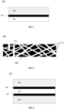
- an exemplary embodiment of an electrode 100 is disclosed for use in an energy storage device, such as an ultracapacitor or battery.
- the electrode includes an electrically conductive layer 102 (also referred to herein as a current collector), an adhesion layer 104, and an active layer 106.
- the active layer 106 may act as energy storage media, for example, by providing a surface interface with an electrolyte (not shown) for formation of an electric double layer (sometimes referred to in the art as a Helmholtz layer).
- the adhesion layer 104 may be omitted, e.g., in cases where the active layer 106 exhibits good adhesion to the electrically conductive layer 102.
- the active layer 106 may be thicker than the adhesion layer 104, e.g., 1.5, 2.0, 5.0, 10, 20, 30, 40, 50, 60, 70, 80, 90, 100, 500, 1,000 or more times the thickness of the adhesion layer 104.
- the thickness of the active layer 106 may be in the range of 1.5 to 1,000 times the thickness of the adhesion layer 104 (or any subrange thereof, such as 5 to 100 times).
- the active layer 106 may have a thickness in the in the range of 0.5 to 2500 ⁇ m or any subrange thereof, e.g., 5 ⁇ m to 150 ⁇ m.
- the adhesion layer 104 may have a thickness in the range of 0.5 ⁇ m to 50 ⁇ m or any subrange thereof, e.g., 1 ⁇ m to 5 ⁇ m.
- the active layer 106 is comprised of carbonaceous material 108 (e.g., activated carbon) bound together by a matrix 110 of CNTs 112 (e.g., a webbing or network formed of CNTs).
- CNTs 112 e.g., a webbing or network formed of CNTs.
- the CNTs 112 forming the matrix 110 may lie primarily parallel to a major surface of the active layer 106.
- the CNTs 112 form straight segments, in some embodiments, e.g., where longer CNTs are used, the some or all of the CNTs may instead have a curved or serpentine shape.
- the CNTs 112 may curve and wind between the lumps.
- the active layer is substantially free of any other binder material, such as polymer materials, adhesives, or the like. In other words, in such embodiments, the active layer is substantially free from any material other than carbon.
- the active layer may be at least about 90 wt %, 95 wt %, 96 wt %, 97 wt %, 98 wt %, 99 wt %, 99.5 wt %, 99.9 wt %, 99.99 wt %, 99.999 wt %, or more elemental carbon by mass.
- the matrix 110 operated to bind together the carbonaceous material 108, e.g., to maintain the structural integrity of the active layer 106 without flaking, delamination, disintegration, or the like.
- the CNTs 112 may include single wall nanotubes (SWNT), double wall nanotubes (DWNT), or multiwall nanotubes (MWNT), or mixtures thereof.
- SWNT single wall nanotubes
- DWNT double wall nanotubes
- MWNT multiwall nanotubes
- the matrix may include interconnected bundles, clusters or aggregates of CNTs.
- the matrix may be made up at least in part of brush like bundles of aligned CNTs.
- the active layer 106 may be formed as follows.
- a first solution also referred to herein as a slurry
- a second solution also referred to herein as a slurry
- This carbon addition includes at least one form of material that is substantially composed of carbon.
- Exemplary forms of the carbon addition include, for example, at least one of activated carbon, carbon powder, carbon fibers, rayon, graphene, aerogel, nanohorns, carbon nanotubes and the like. While in some embodiments, the carbon addition is formed substantially of carbon, it is recognized that in alternative embodiments the carbon addition may include at least some impurities, e.g., additives included by design.
- forming the first and/or second solution include introducing mechanical energy into the mixture of solvent and carbon material, e.g., using a sonicator (sometimes referred to as a sonifier) or other suitable mixing device (e.g., a high shear mixer).
- the mechanical energy introduced into the mixture per kilogram of mixture is at least 0.4 kWh/kg, 0.5 kWh /kg, 0.6 kWh /kg, 0.7 kWh /kg, 0.8 kWh /kg, 0.9 kWh /kg, 1.0 kWh /kg, or more.
- the mechanical energy introduced into the mixture per kilogram of mixture may be in the range of 0.4 kWh/kg to 1.0 kWh/kg or any subrange thereof such as 0.4 kWh/kg to 0.6 kWh/kg.
- the solvents used may include an anhydrous solvent.
- the solvent may include at least one of ethanol, methanol, isopropyl alcohol, dimethyl sulfoxide, dimethylformamide, acetone, acetonitrile, and the like.
- the two solutions may be subjected to "sonication" (physical effects realized in an ultrasonic field).
- the sonication is generally conducted for a period that is adequate to tease out, fluff or otherwise parse the carbon nanotubes.
- the sonication is generally conducted for a period that is adequate to ensure good dispersion or mixing of the carbon additions within the solvent.
- other techniques for imparting mechanical energy to the mixtures may be used in addition or alternative to sonication, e.g., physical mixing using stirring or impeller.
- first solution and the second solution are then mixed together, to provide a combined solution and may again be sonicated.
- the combined mixture is sonicated for a period that is adequate to ensure good mixing of the carbon nanotubes with the carbon addition.
- This second mixing results in the formation of the active layer 106 containing the matrix 110 of CNTs 112, with the carbon addition providing the other carbonaceous material 108 filling the void spaces of the matrix 110.
- the combined slurry may be cast wet directly onto the adhesion layer 104 or the conductive layer 102, and dried (e.g., by applying heat or vacuum or both) until substantially all of the solvent and any other liquids have been removed, thereby forming the active layer 106.
- the combined slurry may be dried elsewhere and then transferred onto the adhesion layer 104 or the conductive layer 102 to form the active layer 106, using any suitable technique (e.g., roll-to-roll layer application).
- the wet combined slurry may be placed onto an appropriate surface and dried to form the active layer 106. While any material deemed appropriate may be used for the surface, exemplary material includes PTFE as subsequent removal from the surface is facilitated by the properties thereof.
- the active layer 106 is formed in a press to provide a layer that exhibits a desired thickness, area and density.
- the average length of the CNTs 112 forming the matrix 110 may be at least 0.1 ⁇ m, 0.5 ⁇ m, 1 ⁇ m, 5 ⁇ m, 10 ⁇ m, 50 ⁇ m, 100 ⁇ m, 200 ⁇ m, 300, ⁇ m, 400 ⁇ m, 500 ⁇ m, 600 ⁇ m, 7000 ⁇ m, 800 ⁇ m, 900 ⁇ m, 1,000 ⁇ m or more.
- the average length of the CNTs 112 forming the matrix 110 may be in the range of 1 ⁇ m to 1,000 ⁇ m, or any subrange thereof, such as 1 ⁇ m to 600 ⁇ m.
- more than 50%, 60%, 70%, 80%, 90%, 95%, 99% or more of the CNTs 112 may have a length within 10% of the average length of the CNTs 112 making up the matrix 110.
- the other carbonaceous material 108 can include carbon in a variety forms, including activated carbon, carbon black, graphite, and others.
- the carbonaceous material can include carbon particles, including nanoparticles, such as nanotubes, nanorods, graphene in sheet, flake, or curved flake form, and/or formed into cones, rods, spheres (buckyballs) and the like.
- an active layer of the type herein can provide exemplary performance (e.g., high conductivity, low resistance, high voltage performance, and high energy and power density) even when the mass fraction of CNTs in the layer is quite low.
- the active layer may be at least about 50 wt %, 60 wt %, 70 wt %, 75 wt %, 80 wt %, 85 wt %, 90 wt %, 95 wt %, 96 wt % 97 wt %, 98 wt %, 99 wt %, 99.5 wt %, or more elemental carbon in a form other than CNT (e.g., activated carbon).
- active layers 106 that are in the range of 95 wt % to 99 wt % activated carbon (with the balance CNTs 112), have been shown to exhibit excellent performance.
- the matrix 110 of CNTs 112 form an interconnected network of highly electrically conductive paths for current flow (e.g. ion transport) through the active layer 106.
- highly conductive junctions may occur at points where CNTs 112 of the matrix 110 intersect with each other, or where they are in close enough proximity to allow for quantum tunneling of charge carriers (e.g., ions) from one CNT to the next.
- the CNTs 112 may make up a relatively low mass fraction of the active layer (e.g., less than 10 wt %, 5 wt %, 4 wt %, 3 wt %, 2 wt%, 1 wt % or less, e.g., in the range of 0.5 wt % to 10 wt % or any subrange thereof such as 1 wt % to 5.0 wt %), the interconnected network of highly electrically conductive paths formed in the matrix 110 may provide long conductive paths to facilitate current flow within and through the active layer 106 (e.g. conductive paths on the order of the thickness of the active layer 106).
- the matrix 110 may include one or more structures of interconnected CNTs, where the structure has an overall length in along one or more dimensions longer than 2, 3, 4, 5, 10, 20, 50, 100, 500, 1,000, 10,000 or more times the average length of the component CNTs making up the structure.
- the matrix 110 may include one or more structures of interconnected CNTs, where the structure has an overall in the range of 2 to 10,000 (or any subrange thereof) times the average length of the component CNTs making up the structure.
- the matrix 110 may include highly conductive pathways having a length greater than 100 ⁇ m, 500 ⁇ m, 1,000 ⁇ m, 10,000 ⁇ m or more, e.g., in the range of 100 ⁇ m - 10,000 ⁇ m of any subrange thereof.
- highly conductive pathway is to be understood as a pathway formed by interconnected CNTs having an electrical conductivity higher than the electrical conductivity of the other carbonaceous material 108 (e.g., activated carbon), surrounding that matrix 110 of CNTs 112.
- the other carbonaceous material 108 e.g., activated carbon
- the matrix 110 can be characterized as an electrically interconnected network of CNT exhibiting connectivity above a percolation threshold.
- Percolation threshold is a mathematical concept related to percolation theory, which is the formation of long-range connectivity in random systems. Below the threshold a so called “giant" connected component of the order of system size does not exist; while above it, there exists a giant component of the order of system size.
- the percolation threshold can be determined by increasing the mass fraction of CNTs 112 in the active layer 106 while measuring the conductivity of the layer, holding all other properties of the layer constant. In some such cases, the threshold can be identified with the mass fraction at which the conductivity of the layer sharply increases and/or the mass fraction above which the conductivity of the layer increases only slowly with increases with the addition of more CNTs. Such behavior is indictive of crossing the threshold required for the formation of interconnected CNT structures that provide conductive pathways with a length on the order of the size of the active layer 106.
- one or both of the active layer 106 and the adhesion layer 104 may be treated by applying heat to remove impurities (e.g., functional groups of the CNTs, and impurities such as moisture, oxides, halides, or the like).
- impurities e.g., functional groups of the CNTs, and impurities such as moisture, oxides, halides, or the like.
- one or both of the layers can be heated to at least 100 C, 150 C, 200 C, 250 C, 300 C, 350 C, 400 C, 450 C, 500 C or more for at least 1 minute, 5 minutes, 10 minutes, 30 minutes, 1 hour, 2 hours, 3 hours, 12 hours, 24 hours, or more.
- the layers may be treated to reduce moisture in the layer to less that 1,000 ppm, 500 ppm, 100 ppm, 10 ppm, 1 ppm, 0.1 ppm or less.
- the adhesion layer 104 may be formed of carbon nanotubes.
- the adhesion layer 104 may be at least about 50%, 75%, 80%, 90%, 95%, 96% 97%, 98%, 99%, 99.5%, 99.9%, 99.99%, 99.999% by mass CNTs.
- the CNTs may be grown directly on the conductive layer 102, e.g., using the chemical vapor deposition techniques such as those described in U.S. Patent Pub. No 20150210548 entitled "In-line Manufacture of Carbon Nanotubes" and published July 30, 2015 .
- the CNTs may be transferred onto the conductive layer 102, e.g., using wet or dry transfer processes, e.g., of the type described e.g., in U.S. Patent Pub. No. 20150279578 entitled "High Power and high Energy Electrodes Using Carbon Nanotubes” and published October 1, 2015 .
- the adhesion layer 104 adheres to the overlying active layer 106 using substantially only electrostatic forces (e.g., Van Der Waals attractions) between the CNTs of the adhesion layer 104 and the carbon material and CNTs of the active layer 106.
- the CNTs of the adhesion layer 104 may include single wall nanotubes (SWNT), double wall nanotubes (DWNT), or multiwall nanotubes (MWNT), or mixtures thereof. In some embodiments the CNTs may be vertically aligned. In one particular embodiment, the CNTs of the adhesion layer 104 may be primarily or entirely SWNTs and/or DWNTs, while the CNTs of the active layer 106 a primarily or entirely MWNTs.
- the CNTs of the of the adhesion layer 104 may be at least 75%, at least 90%, at least 95%, at least 99% or more SWNT or at least 75%, at least 90%, at least 95%, at least 99% or more DWNT.
- the CNTs of the of the active layer 106 may be at least 75%, at least 90%, at least 95%, at least 99% or more MWNT.
- the adhesion layer 104 may be formed by applying pressure to a layer of carbonaceous material. In some embodiments, this compression process alters the structure of the adhesion layer 104 in a way that promotes adhesion to the active layer 106. For example, in some embodiments pressure may be applied to layer comprising a vertically aligned array of CNT or aggregates of vertically aligned CNT, thereby deforming or breaking the CNTs.
- the adhesion layer may be formed by casting a wet slurry of CNTs (with or without additional carbons) mixed with a solvent onto the conductive layer 102. In various embodiments, similar techniques to those described above for the formation of the active layer 106 from a wet slurry may be used.
- mechanical energy may be introduced to the wet slurry using a sonicator (sometimes referred to as a sonifier) or other suitable mixing device (e.g., a high shear mixer).
- a sonicator sometimes referred to as a sonifier
- suitable mixing device e.g., a high shear mixer
- the mechanical energy into the mixture per kilogram of mixture is at least 0.4 kWh/kg, 0.5 kWh /kg, 0.6 kWh /kg, 0.7 kWh /kg, 0.8 kWh /kg, 0.9 kWh /kg, 1.0 kWh /kg, or more.
- the mechanical energy introduced into the mixture per kilogram of mixture may be in the range of 0.4 kWh/kg to 1.0 kWh/kg or any subrange thereof such as 0.4 kWh/kg to 0.6 kWh/kg.
- the solid carbon fraction of the wet slurry may be less than 10 wt %, 5 wt %, 4 wt %, 3 wt %, 2 wt%, 1 wt , 0.5 wt 5, 0.1 wt % or less, e.g., in the range of 0.1 wt % to 10 wt % or any subrange thereof such as 0.1 wt % to 2 wt %.
- the conductive layer 102 may be made of a suitable electrically conductive material such as a metal foil (e.g., an aluminum foil).
- the surface of the conductive layer 102 may be roughened, patterned, or otherwise texturized, e.g., to promote adhesion to the adhesion layer 104 and good electrical conductance from the active layer 106.
- the conductive layer may be etched (e.g., mechanically or chemically).
- the conductive layer 102 may have a thickness in the range of 1 ⁇ m to 1,000 ⁇ m or any subrange thereof such as 5 ⁇ m to 50 ⁇ m.
- the conductive layer 102 may include a nanostructured surface.
- the conductive layer may have a top surface that includes nanoscale features such as whiskers (e.g., carbide whiskers) that promote adhesion to the adhesion layer 104 and good electrical conductance from the active layer 106.
- whiskers e.g., carbide whiskers
- An exemplary current collector is the current collector available from Toyo Aluminum K.K. under the trade name TOYAL-CARBO ® .
- one or both of the active layer 106 and the adhesion layer 104 may be treated by applying heat and/or vacuum to remove impurities (e.g., functional groups of the CNTs, and impurities such as moisture, oxides, halides, or the like).
- impurities e.g., functional groups of the CNTs, and impurities such as moisture, oxides, halides, or the like.
- one or both of the active the active layer 106 and the adhesion layer 104 may be compressed, e.g., to break some of the constituent CNTs or other carbonaceous material to increase the surface area of the respective layer.
- this compression treatment may increase one or more of adhesion between the layers, ion transport rate within the layers, and the surface area of the layers.
- compression can be applied before or after the respective layer is applied to or formed on the electrode 100.
- the adhesion layer 104 may be omitted, such that the active layer 106 is disposed directly on the conductive layer 102.
- the electrode 100 may be double sided, with an adhesion layer 104 and active layer 106 formed on each of two opposing major surfaces of the conductive layer 102.
- the adhesion layer 104 may be omitted on one or both sides of the two-sided electrode 100.
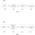
- step 201 CNTs are dispersed in a solvent to form a dispersion of CNTs.
- the dispersion may be formed using any of the techniques described in U.S. Patent Pub. No. 20150279578 entitled "High Power and High Energy Electrodes Using Carbon Nanotubes" published October 1, 2015 including stirring, sonication, or a combination of the two.
- any suitable solvent may be used, including, for example, ethanol, methanol, isopropyl alcohol, dimethyl sulfoxide, dimethylformamide, acetone, acetonitrile, and the like.
- the mixture of CNTs and solvents may be passed through a filter, e.g., an array of micro channels (e.g., having channels with diameters on the order of the radial size of the CNTs) to help physically separate the CNTs and promote dispersion.
- a filter e.g., an array of micro channels (e.g., having channels with diameters on the order of the radial size of the CNTs) to help physically separate the CNTs and promote dispersion.
- the CNT dispersion may be formed without the addition of surfactants, e.g., to avoid the presence of impurities derived from these surfactants at the completion of the method 200.
- the CNT dispersion is mixed with carbonaceous material (e.g., activated carbon) to form a slurry.
- carbonaceous material e.g., activated carbon
- the slurry may be formed using any of the techniques described in U.S. Patent Pub. No. 20150279578, published on October 1, 2015 , including stirring, sonication, or a combination of the two.
- the slurry may have solid carbon fraction of less than 20 wt %, 15 wt %, 10 wt %, 5 wt %, 2 wt %, 1 wt %, or less, e.g., in the range of 1 wt % to 20 wt % or any subrange thereof such as 4% to 6%.
- the mass ratio of CNTs to other carbonaceous material in the slurry may be less than 1:5, 1:10, 1:15, 1:20, 1:50, 1:100, or less, e.g., in the range of 1:10 to 1:20 or any subrange thereof.
- the slurry is applied to either the adhesion layer 104 or, if the adhesion layer 104 is omitted, the conductive layer 102 of the electrode 100.
- the slurry may be formed into a sheet, and coated onto the electrode.
- slurry may be applied to through a slot die to control the thickness of the applied layer.
- the slurry may be applied to the conductive layer 102, and then leveled to a desired thickness, e.g., using a doctor blade.
- the slurry may be compressed (e.g., using a calendaring apparatus) before or after being applied to the electrode 100.
- the slurry may be partially or completely dried (e.g., by applying heat, vacuum or a combination thereof) during this step 203.
- step 204 if the slurry has not dried, or has been only partially dried during step 203, the slurry applied to the electrode is fully dried, (e.g., by applying heat, vacuum or a combination thereof). In some embodiments, substantially all of the solvent (and any other non-carbonaceous material such as dispersing agents) is removed from the active layer 106. In some embodiments, if impurities remain following the drying step, and additional step of heating (e.g. baking or annealing) the layer may be performed.
- additional step of heating e.g. baking or annealing
- one or both of the active the active layer 106 and the adhesion layer 104 may be treated by applying heat to remove impurities (e.g., functional groups of the CNTs, and impurities such as moisture, oxides, halides, or the like).
- impurities e.g., functional groups of the CNTs, and impurities such as moisture, oxides, halides, or the like.
- step 301 CNTs are dispersed in a solvent to form a dispersion of CNTs.
- the dispersion may be formed using any of the techniques described in U.S. Patent Pub. No. 20150279578, published on October 1, 2015 , including stirring, sonication, or a combination of the two.
- any suitable solvent may be used, including, for example an organic solvent such as isopropyl alcohol, acetonitrile or propylene carbonate. In general, it is advantageous to choose a solvent that will be substantially eliminated in the drying step 304 described below.
- the mixture of CNTs and solvents may be passed through a filter, e.g., an array of micro channels (e.g., having channels with diameters on the order of the radial size of the CNTs) to help physically separate the CNTs and promote dispersion.
- a filter e.g., an array of micro channels (e.g., having channels with diameters on the order of the radial size of the CNTs) to help physically separate the CNTs and promote dispersion.
- the CNT dispersion may be formed without the addition of surfactants, e.g., to avoid the presence of impurities derived from these surfactants at the completion of the method 300.
- the CNT dispersion may optionally be mixed with additional carbonaceous material (e.g., activated carbon) to form a slurry.
- additional carbonaceous material e.g., activated carbon
- the additional carbonaceous material may be omitted, such that the slurry is made up of CNTs dispersed in a solvent.
- the slurry may have solid fraction of less than 5 wt %, 4 wt %, 3 wt %, 2 wt %, 1 wt %, 0.5 wt %, 0.1 wt %, or less, e.g., in the range of 0.1 to 5 wt % or any subrange thereof.
- the slurry is applied to the conductive layer 102 of the electrode 100.
- the slurry may be coated onto the electrode.
- slurry may be applied to through a slot die to control the thickness of the applied layer.
- the slurry may be applied to the conductive layer 102, and then leveled to a desired thickness, e.g., using a doctor blade.
- the slurry may be compressed (e.g., using a calendaring apparatus) before or after being applied to the electrode 100.
- the slurry may be partially or completely dried (e.g., by applying heat, vacuum or a combination thereof) during this step 303.
- step 304 if the slurry has not dried, or has been only partially dried during step 203, the slurry applied to the electrode is fully dried, (e.g., by applying heat, vacuum or a combination thereof). In some embodiments, substantially all of the solvent (and any other non-carbonaceous material such as dispersing agents) is removed from the active layer 106. In some embodiments, if impurities remain following the drying step, and additional step of heating (e.g. baking or annealing) the layer may be performed.
- additional step of heating e.g. baking or annealing
- one or both of the active the active layer 106 and the adhesion layer 104 may be treated by applying heat to remove impurities (e.g., functional groups of the CNTs, and impurities such as moisture, oxides, halides, or the like).
- impurities e.g., functional groups of the CNTs, and impurities such as moisture, oxides, halides, or the like.
- the method 300 for forming an adhesion layer 104 and method 200 for forming an active layer 106 may be performed in series to successively form the adhesion layer 104 followed by the overlaying active layer 106. In some embodiments, the foregoing methods may be repeated, e.g., to form a two-sided electrode of the type described herein.
- the method 300 for forming an adhesion layer 104 and/or method 200 for forming an active layer 106 may be implemented as a roll-to-roll processes, e.g., to allow volume production of electrode sheets several tens of meters long or more.
- FIG. 6 shows an exemplary mixing apparatus 400 for implementing the method 300 for forming an adhesion layer 104 and/or method 200 for forming an active layer 106.
- the apparatus 400 will be described for use in forming active layer 106 using method 200.
- the apparatus 400 can easily be configured to implement the method 300 for forming an adhesion layer 104.
- the apparatus 400 includes a mixing vessel 401.
- the mixing vessel receives a slurry composed of a solvent, carbon nanotubes, and (optionally) additional carbonaceous material of the type described above.
- this slurry (or components thereof) may be initially formed in the mixing vessel 401. In other embodiments, the slurry may be formed elsewhere and then transferred to the mixing vessel 401.
- the mixing vessel 401 may include one or more mechanisms for mixing the slurry, such as an impeller or high sheer mixer.
- a mixing mechanism may be provided which is capable of stirring the slurry at a controlled rate, e.g., of up to 1000 rotations per minute (RPM) or more.
- the mixing vessel may include one or more devices for applying mechanical energy to the slurry, such as a sonicator, mixer (e.g., a high shear mixer), homogenizer, or any other suitable device known in the art.
- the mixing vessel may be temperature controlled, e.g., using one or more heating and/or cooling elements such as electric heaters, tubing for circulating chilled water, or any other such devices known in the art.
- Slurry from the mixing vessel 401 may be circulated through a flow line 402, e.g. a pipe or tubing, using a pump 403.
- Pump 403 may be any suitable configuration, such as a peristaltic pump.
- a flow meter 404 may be provided to measure the rate of slurry flow through the flow line 402.
- a filter 405 may be provided to filter the slurry flowing through the flow line 402, e.g., to remove clumps of solid material having a size above a desired threshold.
- an in-line sonicator 406 may be provided to sonicate slurry flowing through the flow line 402.
- a flow through sonicator such as the Branson Digital SFX-450 sonicator available commercially from Thomas Scientific of 1654 High Hill Road Swedesboro, NJ 08085 U.S.A may be used.
- a temperature control device 407 such as a heat exchanger arranged in a sleeve disposed about the flow line 402, is provided to control the temperature of the slurry flowing through the flow line 402.
- a valve 408 is provided which can be selectively controlled to direct a first portion of the slurry flowing through flow line 402 to be recirculated back to the mixing vessel 401, while a second portion is output externally, e.g., to a coating apparatus 500.
- a sensor 409 such as a pressure sensor or flow rate sensor is provided to sense one or more aspects of the output portion of slurry.
- any or all of the elements of apparatus 400 may be operatively connected to one or more computing devices to provide for automatic monitoring and/or control of the mixing apparatus 400.
- the sonicator 406 may include digital controls for controlling its operating parameters such as power and duty cycle.
- the coating apparatus 500 may be any suitable type known in the art.
- FIG. 7A shows an exemplary embodiment of coating apparatus 500 featuring a slot die 501 that distributes slurry received from a source such as the mixing apparatus 400 through a distribution channel 502 onto a substrate 503 (e.g., the conductive layer 102, either bare or already coated with adhesion layer 104) which moves across a roller 504.
- a substrate 503 e.g., the conductive layer 102, either bare or already coated with adhesion layer 104
- Setting the height of the slot die above the substrate 503 on the roller 504 and controlling the flow rate and/or pressure of the slurry in the channel 502 allows for control of the thickness and density of the applied coating.
- channel 502 may include one or more reservoirs to help ensure consistent flow of slurry to provide uniform coating during operation.
- FIG. 7B shows an exemplary embodiment of coating apparatus 500 featuring a doctor blade 601 that levels slurry received from a source such as the mixing apparatus 400 that is applied through on or more applicators 602 (one is shown) onto a substrate 603 (e.g., the conductive layer 102, either bare or already coated with adhesion layer 104) which moves across a roller 604.
- a substrate 603 e.g., the conductive layer 102, either bare or already coated with adhesion layer 10
- the direction of travel of the substrate 603 is indicated by the heavy dark arrow. Setting the height of the doctor blade 601 above the substrate 603 on the roller 604 and controlling the flow rate and/or pressure of the slurry through the applicator 602 allows for control of the thickness and density of the applied coating.
- a single doctor blade 601 is shown, multiple blades may be used, e.g., a first blade to set a rough thickness of the coating, and a second blade positioned down line form the first blade to provide fine smooth
- Such ultracapacitors may comprise an energy storage cell and an electrolyte system within an hermetically sealed housing, the cell electrically coupled to a positive contact and a negative contact, wherein the ultracapacitor is configured to operate at a temperatures within a temperature range between about -100 degrees Celsius to about 300 degrees Celsius or more, or any subrange thereof, e.g., -40 C to 200 C, -40 C to 250 C, -40 C to 300 C, 0 C to 200 C, 0 C to 250 C, 0 C to 300 C.
- such ultracapacitors can operate a voltages of 1.0 V, 2.0 V, 3.0 V, 3.2 V, 3.5 V. 4.0 V, or more, e.g., for lifetimes exceeding 1,000 hours.
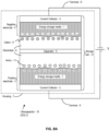
- FIGS. 8A and 8B exemplary embodiments of a capacitor are shown.
- the capacitor is an "ultracapacitor 10."
- FIG. 8A and FIG. 8B The difference between FIG. 8A and FIG. 8B is the inclusion of a separator in exemplary ultracapacitor 10 of FIG. 8A .
- the concepts disclosed herein generally apply equally to any exemplary ultracapacitor 10. Certain electrolytes of certain embodiments are uniquely suited to constructing an exemplary ultracapacitor 10 without a separator. Unless otherwise noted, the discussion herein applies equally to any ultracapacitor 10, with or without a separator.
- the exemplary ultracapacitor 10 is an electric double-layer capacitor (EDLC).
- the EDLC includes at least one pair of electrodes 3 (where the electrodes 3 may be referred to as a negative electrode 3 and a positive electrode 3, merely for purposes of referencing herein).
- each of the electrodes 3 (which may each be an electrode 100 of the type shown in FIG. 1 above) presents a double layer of charge at an electrolyte interface.
- a plurality of electrodes 3 is included (for example, in some embodiments, at least two pairs of electrodes 3 are included). However, for purposes of discussion, only one pair of electrodes 3 are shown.
- At least one of the electrodes 3 uses a carbon-based energy storage media 1 (e.g., the active layer 106 of electrode 100 shown in FIG. 1 ), and it assumed that each of the electrodes includes the carbon-based energy storage media 1.
- a carbon-based energy storage media 1 e.g., the active layer 106 of electrode 100 shown in FIG. 1
- each of the electrodes includes the carbon-based energy storage media 1.
- an electrolytic capacitor differs from an ultracapacitor because metallic electrodes differ greatly (at least an order of magnitude) in surface area.
- Each of the electrodes 3 includes a respective current collector 2 (also referred to as a "charge collector"), which may be the conductive layer 102 of electrode 100 shown in FIG. 1 .
- the electrodes 3 are separated by a separator 5.
- the separator 5 is a thin structural material (usually a sheet) used to separate the negative electrode 3 from the positive electrode 3.
- the separator 5 may also serve to separate pairs of the electrodes 3.
- the electrodes 3 and the separator 5 provide a storage cell 12.
- the carbon-based energy storage media 1 may not be included on one or both of the electrodes 3. That is, in some embodiments, a respective electrode 3 might consist of only the current collector 2.
- electrode 3 generally refers to a combination of the energy storage media 1 and the current collector 2 (but this is not limiting, for at least the foregoing reason).
- At least one form of electrolyte 6 is included in the ultracapacitor 10.
- the electrolyte 6 fills void spaces in and between the electrodes 3 and the separator 5.
- the electrolyte 6 is a substance that disassociates into electrically charged ions.
- a solvent that dissolves the substance may be included in some embodiments of the electrolyte 6, as appropriate.
- the electrolyte 6 conducts electricity by ionic transport.
- the electrolyte 6 may be in gelled or solid form (e.g., an ionic liquid impregnated polymer layer).
- gelled or solid form e.g., an ionic liquid impregnated polymer layer.
- Examples of such electrolytes are provided in International Publication No. WO 2015/102716 entitled “ADVANCED ELECTROLYTES FOR HIGH TEMPERATURE ENERGY STORAGE DEVICE” and published July 9, 2015 .
- the electrolyte 6 may be in non-aqueous liquid form, e.g., an ionic liquid, e.g., of a type suitable for high temperature applications.
- ionic liquid e.g., of a type suitable for high temperature applications.
- Examples of such electrolytes are provided in International Publication No. WO 2015/102716 entitled “ADVANCED ELECTROLYTES FOR HIGH TEMPERATURE ENERGY STORAGE DEVICE” and published July 9, 2015 .
- the storage cell 12 is formed into one of a wound form or prismatic form which is then packaged into a cylindrical or prismatic housing 7.
- the housing 7 may be hermetically sealed.
- the package is hermetically sealed by techniques making use of laser, ultrasonic, and/or welding technologies.
- the housing 7 is configured with external contacts to provide electrical communication with respective terminals 8 within the housing 7.
- Each of the terminals 8, in turn, provides electrical access to energy stored in the energy storage media 1, generally through electrical leads which are coupled to the energy storage media 1.
- hermetic refers to a seal whose quality (i.e., leak rate) is defined in units of "atm-cc/second,” which means one cubic centimeter of gas (e.g., He) per second at ambient atmospheric pressure and temperature. This is equivalent to an expression in units of "standard He-cc/sec.” Further, it is recognized that 1 atm-cc/sec is equal to 1.01325 mbar-liter/sec.
- the ultracapacitor 10 disclosed herein is capable of providing a hermetic seal that has a leak rate no greater than about 5.0 ⁇ 10 -6 atm-cc/sec, and may exhibit a leak rate no higher than about 5.0 ⁇ 10 -10 atm-cc/sec. It is also considered that performance of a successfully hermetic seal is to be judged by the user, designer or manufacturer as appropriate, and that "hermetic" ultimately implies a standard that is to be defined by a user, designer, manufacturer or other interested party.
- Leak detection may be accomplished, for example, by use of a tracer gas.
- tracer gas such as helium for leak testing is advantageous as it is a dry, fast, accurate and non destructive method.
- the ultracapacitor 10 is placed into an environment of helium.
- the ultracapacitor 10 is subjected to pressurized helium.
- the ultracapacitor 10 is then placed into a vacuum chamber that is connected to a detector capable of monitoring helium presence (such as an atomic absorption unit). With knowledge of pressurization time, pressure and internal volume, the leak rate of the ultracapacitor 10 may be determined.
- At least one lead (which may also be referred to herein as a "tab”) is electrically coupled to a respective one of the current collectors 2.
- a plurality of the leads (accordingly to a polarity of the ultracapacitor 10) may be grouped together and coupled to into a respective terminal 8.
- the terminal 8 may be coupled to an electrical access, referred to as a "contact” (e.g., one of the housing 7 and an external electrode (also referred to herein for convention as a "feed-through” or "pin”)).
- a contact e.g., one of the housing 7 and an external electrode (also referred to herein for convention as a "feed-through” or "pin)
- Suitable exemplary designs are provided in International Publication No. WO 2015/102716 entitled “ADVANCED ELECTROLYTES FOR HIGH TEMPERATURE ENERGY STORAGE DEVICE” and published July 9, 2015 .
- ultracapacitor 10 may be joined together.
- the various forms may be joined using known techniques, such as welding contacts together, by use of at least one mechanical connector, by placing contacts in electrical contact with each other and the like.
- a plurality of the ultracapacitors 10 may be electrically connected in at least one of a parallel and a series fashion.
- wt% means weight percent.
- wt% refers to the percentage of the overall mass of the solute and solvent mixture made up by the solute.
Landscapes
- Engineering & Computer Science (AREA)
- Power Engineering (AREA)
- Chemical & Material Sciences (AREA)
- Microelectronics & Electronic Packaging (AREA)
- Materials Engineering (AREA)
- Electrochemistry (AREA)
- General Chemical & Material Sciences (AREA)
- Chemical Kinetics & Catalysis (AREA)
- Crystallography & Structural Chemistry (AREA)
- Nanotechnology (AREA)
- Manufacturing & Machinery (AREA)
- Inorganic Chemistry (AREA)
- Electric Double-Layer Capacitors Or The Like (AREA)
- Carbon And Carbon Compounds (AREA)
- Battery Electrode And Active Subsutance (AREA)
Claims (15)
- Appareil de stockage d'énergie comprenant :une couche active (106) comprenant :un réseau de nanotubes de carbone (112) définissant des espaces vides ; etun matériau carboné (108) situé dans les espaces vides et lié par le réseau de nanotubes de carbone (112) ; etune couche d'adhérence (104) disposée entre la couche active (106) et une couche électriquement conductrice (102), ladite couche d'adhérence (104) comprenant au moins cinquante pour cent de nanotubes de carbone (CNT) en poids ;ladite couche active (106) étant conçue pour assurer un stockage d'énergie ;ladite couche active (106) étant sensiblement exempte d'agents liants et étant constituée essentiellement de matériau carboné ;ladite couche active (106) étant liée conjointement et à la couche d'adhérence (104) par des forces entre les nanotubes de carbone (112) et le matériau carboné (108) ;ledit réseau de nanotubes de carbone (112) représentant moins de dix pour cent en poids de la couche active (106) ;ledit réseau de nanotubes de carbone (112) comprenant un réseau de nanotubes de carbone interconnecté électriquement (112) présentant une connectivité supérieure au seuil de percolation ;ledit réseau de nanotubes de carbone interconnecté (112) comprenant un ou plusieurs chemins conducteurs, lesdits chemins comprenant une longueur supérieure à 100 µm.
- Appareil selon la revendication 1, ledit matériau carboné (108) comprenant du carbone actif.
- Appareil selon la revendication 1, ledit matériau carboné (108) comprend du carbone nanoforme autre que des nanotubes de carbone.
- Appareil selon la revendication 1, ledit réseau de nanotubes de carbone interconnecté (112) comprenant des chemins conducteurs conçus pour faciliter la circulation du courant à l'intérieur de la couche active (106) et à travers celle-ci.
- Appareil selon la revendication 4, lesdits chemins conducteurs présentant une longueur de l'ordre de l'épaisseur de la couche active (106).
- Appareil selon la revendication 1, ledit réseau de nanotubes de carbone (112) représentant moins de 5 % en poids de la couche active (106).
- Appareil selon la revendication 1, une surface de la couche électriquement conductrice (102) faisant face à la couche d'adhérence (104) comprenant une partie rugosifiée ou texturée, ou en variante, une surface de la couche électriquement conductrice (102) faisant face à la couche d'adhérence (104) comprenant une partie nanostructurée.
- Appareil selon la revendication 7, ladite partie nanostructurée comprenant des nano-barbes de carbure.
- Appareil selon la revendication 1, lesdits chemins conducteurs comprenant des chemins présentant une longueur supérieure à 500 µm.
- Appareil selon la revendication 1, lesdits nanotubes de carbone de la couche d'adhérence (104) étant des nanotubes de carbone à paroi unique, des nanotubes de carbone à double paroi ou des nanotubes de carbone à parois multiples.
- Dispositif de stockage d'énergie comprenant :une paire d'électrodes (3, 100) séparées par un séparateur perméable (5) ; etun électrolyte (6) mouillant les électrodes (3, 100) et le séparateur (5) ;une couche active (106) de chacune des électrodes (3, 100) comprenant :un réseau de nanotubes de carbone (112) définissant des espaces vides ; etun matériau carboné (108) situé dans les espaces vides et lié par le réseau de nanotubes de carbone (112) ; etune couche d'adhérence (104) disposée entre la couche active (106) et un collecteur de courant (2), la couche d'adhérence (104) comprenant au moins cinquante pour cent de nanotubes de carbone (CNT) en poids ;ladite couche active (106) étant conçue pour assurer un stockage d'énergie ;ladite couche active (106) étant sensiblement exempte d'agents liants et étant constituée essentiellement de matériau carboné ;ladite couche active (106) étant liée conjointement et à la couche d'adhérence (104) par des forces entre les nanotubes de carbone (112) et le matériau carboné (108) ;ledit réseau de nanotubes de carbone (112) représentant moins de dix pour cent en poids de la couche active (106) ;ledit réseau de nanotubes de carbone (112) comprenant un réseau de nanotubes de carbone interconnecté électriquement présentant une connectivité supérieure au seuil de percolation ;ledit réseau de nanotubes de carbone interconnecté (112) comprenant un ou plusieurs chemins conducteurs, lesdits chemins comprenant une longueur supérieure à 100 µm.
- Dispositif de stockage d'énergie selon la revendication 11, ledit dispositif de stockage d'énergie présentant une tension de fonctionnement supérieure ou égale à 3,0 V.
- Dispositif de stockage d'énergie selon la revendication 12, ledit dispositif de stockage d'énergie présentant une température de fonctionnement maximale supérieure ou égale à 250°C à une tension de fonctionnement supérieure ou égale à 2 V pendant une durée de vie supérieure ou égale à 1 000 heures.
- Dispositif de stockage d'énergie selon la revendication 12, ledit dispositif de stockage d'énergie présentant une température de fonctionnement maximale supérieure ou égale à 300°C à une tension de fonctionnement supérieure ou égale à 1 V pendant une durée de vie supérieure ou égale à 1 000 heures.
- Dispositif de stockage d'énergie selon la revendication 11, ledit dispositif de stockage d'énergie étant une batterie ou un supercondensateur (10).
Priority Applications (1)
| Application Number | Priority Date | Filing Date | Title |
|---|---|---|---|
| EP23184852.4A EP4243122A3 (fr) | 2016-12-02 | 2017-12-01 | Electrode composite |
Applications Claiming Priority (2)
| Application Number | Priority Date | Filing Date | Title |
|---|---|---|---|
| US201662429727P | 2016-12-02 | 2016-12-02 | |
| PCT/US2017/064152 WO2018102652A1 (fr) | 2016-12-02 | 2017-12-01 | Electrode composite |
Related Child Applications (2)
| Application Number | Title | Priority Date | Filing Date |
|---|---|---|---|
| EP23184852.4A Division EP4243122A3 (fr) | 2016-12-02 | 2017-12-01 | Electrode composite |
| EP23184852.4A Division-Into EP4243122A3 (fr) | 2016-12-02 | 2017-12-01 | Electrode composite |
Publications (3)
| Publication Number | Publication Date |
|---|---|
| EP3549148A1 EP3549148A1 (fr) | 2019-10-09 |
| EP3549148A4 EP3549148A4 (fr) | 2020-07-29 |
| EP3549148B1 true EP3549148B1 (fr) | 2025-01-01 |
Family
ID=62242754
Family Applications (2)
| Application Number | Title | Priority Date | Filing Date |
|---|---|---|---|
| EP17876365.2A Active EP3549148B1 (fr) | 2016-12-02 | 2017-12-01 | Electrode composite |
| EP23184852.4A Pending EP4243122A3 (fr) | 2016-12-02 | 2017-12-01 | Electrode composite |
Family Applications After (1)
| Application Number | Title | Priority Date | Filing Date |
|---|---|---|---|
| EP23184852.4A Pending EP4243122A3 (fr) | 2016-12-02 | 2017-12-01 | Electrode composite |
Country Status (7)
| Country | Link |
|---|---|
| US (4) | US11450488B2 (fr) |
| EP (2) | EP3549148B1 (fr) |
| JP (4) | JP7554556B2 (fr) |
| KR (2) | KR102660440B1 (fr) |
| CN (2) | CN117198764A (fr) |
| MX (2) | MX2019006454A (fr) |
| WO (1) | WO2018102652A1 (fr) |
Families Citing this family (18)
| Publication number | Priority date | Publication date | Assignee | Title |
|---|---|---|---|---|
| US11270850B2 (en) | 2013-12-20 | 2022-03-08 | Fastcap Systems Corporation | Ultracapacitors with high frequency response |
| CN113539696B (zh) | 2014-10-09 | 2024-12-03 | 快帽系统公司 | 用于储能装置的纳米结构化电极 |
| US11830672B2 (en) | 2016-11-23 | 2023-11-28 | KYOCERA AVX Components Corporation | Ultracapacitor for use in a solder reflow process |
| EP3549148B1 (fr) | 2016-12-02 | 2025-01-01 | Fastcap Systems Corporation | Electrode composite |
| KR102918331B1 (ko) | 2017-10-03 | 2026-01-27 | 패스트캡 울트라커패시터즈 엘엘씨 | 칩형 울트라캐패시터 |
| CN110660591B (zh) * | 2018-06-29 | 2020-12-04 | 清华大学 | 可拉伸电容器电极-导体结构及超级电容器 |
| CN113195230A (zh) | 2018-11-30 | 2021-07-30 | 纽约州州立大学研究基金会 | 用于将石墨烯从金属衬底中转移出来的方法 |
| US11557765B2 (en) | 2019-07-05 | 2023-01-17 | Fastcap Systems Corporation | Electrodes for energy storage devices |
| US10840032B1 (en) * | 2020-03-24 | 2020-11-17 | Yazaki Corporation | Supercapacitor cell with high-purity binder-free carbonaceous electrode |
| JP2023533968A (ja) * | 2020-07-07 | 2023-08-07 | ファーストキャップ・システムズ・コーポレイション | エネルギー貯蔵デバイス用の貯蔵セルを提供するための方法及び装置 |
| EP4189767A1 (fr) * | 2020-07-31 | 2023-06-07 | Cummins, Inc. | Remise à neuf d'une cellule de batterie |
| WO2022072047A1 (fr) * | 2020-09-29 | 2022-04-07 | Fastcap Systems Corporation | Dispositifs de stockage d'énergie |
| US20230360863A1 (en) * | 2020-10-19 | 2023-11-09 | Fastcap Systems Corporation | Advanced lithium-ion energy storage device |
| KR20240110017A (ko) * | 2021-11-12 | 2024-07-12 | 패스트캡 시스템즈 코포레이션 | 에너지 저장 디바이스 |
| EP4449464A4 (fr) * | 2021-12-16 | 2026-01-07 | Nanoramic Inc | Électrodes pour dispositifs de stockage d'énergie |
| USD1066734S1 (en) * | 2023-02-03 | 2025-03-11 | Becton, Dickinson And Company | Cartridge |
| USD1057200S1 (en) | 2023-02-03 | 2025-01-07 | Becton, Dickinson And Company | Analysis system |
| IT202300028194A1 (it) * | 2023-12-28 | 2025-06-28 | Novac S R L | Collettore di corrente per accumulatori di energia elettrica |
Family Cites Families (333)
| Publication number | Priority date | Publication date | Assignee | Title |
|---|---|---|---|---|
| US3185903A (en) | 1961-06-15 | 1965-05-25 | Chicago Condenser Corp | Hermetically sealed variable capacitor |
| US3982182A (en) | 1973-08-13 | 1976-09-21 | Coulter Electronics, Inc. | Conductivity cell for particle study device |
| US4408259A (en) | 1979-02-09 | 1983-10-04 | Matsushita Electric Industrial Company, Limited | Electrochemical double-layer capacitor |
| US4252873A (en) | 1979-07-30 | 1981-02-24 | Battery Engineering, Inc. | Seal for electrochemical cell |
| US4349910A (en) | 1979-09-28 | 1982-09-14 | Union Carbide Corporation | Method and apparatus for orientation of electrode joint threads |
| US4604676A (en) | 1984-10-02 | 1986-08-05 | Murata Manufacturing Co., Ltd. | Ceramic capacitor |
| JPS63261811A (ja) | 1987-04-20 | 1988-10-28 | 松下電器産業株式会社 | 電気二重層コンデンサ |
| JPH01220424A (ja) | 1988-02-29 | 1989-09-04 | Hitachi Condenser Co Ltd | 電気二重層コンデンサ |
| US4934366A (en) | 1988-09-01 | 1990-06-19 | Siemens-Pacesetter, Inc. | Feedthrough connector for implantable medical device |
| JPH0278211A (ja) | 1988-09-13 | 1990-03-19 | Murata Mfg Co Ltd | 積層セラミックコンデンサ |
| NL9001976A (nl) | 1990-09-07 | 1992-04-01 | Kinetron Bv | Generator. |
| JPH05159972A (ja) | 1991-12-06 | 1993-06-25 | Matsushita Electric Ind Co Ltd | 電気二重層コンデンサ |
| JPH05234814A (ja) | 1992-02-24 | 1993-09-10 | Murata Mfg Co Ltd | 電気二重層コンデンサ |
| CH686206A5 (it) | 1992-03-26 | 1996-01-31 | Asulab Sa | Cellule photoelectrochimique regeneratrice transparente. |
| US5476709A (en) | 1992-06-15 | 1995-12-19 | Mitsui Toatsu Chemicals, Inc. | Polymeric insulating material and formed article making use of the material |
| US5711988A (en) | 1992-09-18 | 1998-01-27 | Pinnacle Research Institute, Inc. | Energy storage device and its methods of manufacture |
| EP0662248A4 (fr) | 1992-09-18 | 2000-10-25 | Pinnacle Research Inst Inc | Dispositif d'accumulation d'energie et son procede de fabrication |
| US5426561A (en) | 1992-09-29 | 1995-06-20 | The United States Of America As Represented By The United States National Aeronautics And Space Administration | High energy density and high power density ultracapacitors and supercapacitors |
| US5440447A (en) | 1993-07-02 | 1995-08-08 | The Morgan Crucible Company, Plc | High temperature feed-through system and method for making same |
| US5564235A (en) | 1994-08-29 | 1996-10-15 | Butler; Michael | Foundation and floor construction means |
| US5621607A (en) | 1994-10-07 | 1997-04-15 | Maxwell Laboratories, Inc. | High performance double layer capacitors including aluminum carbon composite electrodes |
| US5905629A (en) | 1995-09-28 | 1999-05-18 | Westvaco Corporation | High energy density double layer energy storage devices |
| US6060424A (en) | 1995-09-28 | 2000-05-09 | Westvaco Corporation | High energy density carbons for use in double layer energy storage devices |
| JPH09293490A (ja) | 1996-04-25 | 1997-11-11 | Seiko Instr Kk | 密閉電池およびその製造方法 |
| AU721291C (en) | 1996-05-15 | 2003-02-27 | Hyperion Catalysis International, Inc. | Graphitic nanofibers in electrochemical capacitors |
| US5710699A (en) | 1996-05-28 | 1998-01-20 | General Electric Company | Power electronic interface circuits for batteries and ultracapacitors in electric vehicles and battery storage systems |
| US6194815B1 (en) | 1996-10-25 | 2001-02-27 | Ocean Power Technology, Inc. | Piezoelectric rotary electrical energy generator |
| BR9807239A (pt) | 1997-02-19 | 2000-04-25 | Starck H C Gmbh Co Kg | Pós de tântalo, processos para a sua preparação, bem como anodos de sinterização preparados a partir deles |
| US6683783B1 (en) | 1997-03-07 | 2004-01-27 | William Marsh Rice University | Carbon fibers formed from single-wall carbon nanotubes |
| US5982156A (en) | 1997-04-15 | 1999-11-09 | The United States Of America As Represented By The Secretary Of The Air Force | Feed-forward control of aircraft bus dc boost converter |
| US6205016B1 (en) | 1997-06-04 | 2001-03-20 | Hyperion Catalysis International, Inc. | Fibril composite electrode for electrochemical capacitors |
| US6843119B2 (en) | 1997-09-18 | 2005-01-18 | Solinst Canada Limited | Apparatus for measuring and recording data from boreholes |
| US5853794A (en) | 1997-10-31 | 1998-12-29 | Kemet Electronics Corp. | Doped polyaniline solutions |
| JPH11145002A (ja) | 1997-11-06 | 1999-05-28 | Asahi Glass Co Ltd | 電気二重層キャパシタ用セパレータ前駆体及び電気二重層キャパシタ |
| US6511760B1 (en) | 1998-02-27 | 2003-01-28 | Restek Corporation | Method of passivating a gas vessel or component of a gas transfer system using a silicon overlay coating |
| US6193032B1 (en) | 1998-03-02 | 2001-02-27 | The Penn State Research Foundation | Piezoceramic vibration control device and tuning control thereof |
| US6247533B1 (en) | 1998-03-09 | 2001-06-19 | Seismic Recovery, Llc | Utilization of energy from flowing fluids |
| US6141205A (en) | 1998-04-03 | 2000-10-31 | Medtronic, Inc. | Implantable medical device having flat electrolytic capacitor with consolidated electrode tabs and corresponding feedthroughs |
| US5945749A (en) | 1998-06-10 | 1999-08-31 | Westinghouse Air Brake Company | On-board electrical power generator operated by vibration or compressed air |
| AU771319B2 (en) | 1998-09-28 | 2004-03-18 | Hyperion Catalysis International, Inc. | Fibril composite electrode for electrochemical capacitors |
| US6201685B1 (en) | 1998-10-05 | 2001-03-13 | General Electric Company | Ultracapacitor current collector |
| US6232706B1 (en) | 1998-11-12 | 2001-05-15 | The Board Of Trustees Of The Leland Stanford Junior University | Self-oriented bundles of carbon nanotubes and method of making same |
| US6470974B1 (en) | 1999-04-14 | 2002-10-29 | Western Well Tool, Inc. | Three-dimensional steering tool for controlled downhole extended-reach directional drilling |
| SE518454C2 (sv) | 1999-01-15 | 2002-10-08 | Forskarpatent I Uppsala Ab | Metod för framställning av en elektrokemisk cell samt elektrokemisk cell |
| US6346187B1 (en) | 1999-01-21 | 2002-02-12 | The Regents Of The University Of California | Alternating-polarity operation for complete regeneration of electrochemical deionization system |
| SE9900213D0 (sv) | 1999-01-26 | 1999-01-26 | Sandvik Ab | Manufacture of transition metal carbide and carbonitride whiskers with low residual amounts of oxygen and intermediate oxide phases |
| US6118251A (en) | 1999-01-27 | 2000-09-12 | The United States Of America As Represented By The Secretary Of The Army | Battery depassivation and conditioning method and apparatus |
| MY120832A (en) | 1999-02-01 | 2005-11-30 | Shell Int Research | Multilateral well and electrical transmission system |
| US6444326B1 (en) | 1999-03-05 | 2002-09-03 | Restek Corporation | Surface modification of solid supports through the thermal decomposition and functionalization of silanes |
| US6716554B2 (en) | 1999-04-08 | 2004-04-06 | Quallion Llc | Battery case, cover, and feedthrough |
| EP1059266A3 (fr) | 1999-06-11 | 2000-12-20 | Iljin Nanotech Co., Ltd. | Procédé de synthèse de masse de nanotubes de carbone de grande pureté, alignés verticalement sur un substrat de grande dimension, obtenus par déposition thermique en phase vapeur |
| EP1061554A1 (fr) | 1999-06-15 | 2000-12-20 | Iljin Nanotech Co., Ltd. | Source de lumière blanche à nanotubes de carbone et procédé de fabrication |
| US6449139B1 (en) | 1999-08-18 | 2002-09-10 | Maxwell Electronic Components Group, Inc. | Multi-electrode double layer capacitor having hermetic electrolyte seal |
| US6257332B1 (en) | 1999-09-14 | 2001-07-10 | Halliburton Energy Services, Inc. | Well management system |
| JP2001160525A (ja) | 1999-09-24 | 2001-06-12 | Honda Motor Co Ltd | 分極性電極用活性炭の前処理方法 |
| TW497286B (en) | 1999-09-30 | 2002-08-01 | Canon Kk | Rechargeable lithium battery and process for the production thereof |
| US6413285B1 (en) | 1999-11-01 | 2002-07-02 | Polyplus Battery Company | Layered arrangements of lithium electrodes |
| US6304427B1 (en) | 2000-01-07 | 2001-10-16 | Kemet Electronics Corporation | Combinations of materials to minimize ESR and maximize ESR stability of surface mount valve-metal capacitors after exposure to heat and/or humidity |
| US6679332B2 (en) | 2000-01-24 | 2004-01-20 | Shell Oil Company | Petroleum well having downhole sensors, communication and power |
| WO2002010553A1 (fr) | 2000-01-28 | 2002-02-07 | Halliburton Energy Services, Inc. | Generateur d'energie a partir de vibrations |
| KR100487069B1 (ko) | 2000-04-12 | 2005-05-03 | 일진나노텍 주식회사 | 새로운 물질로 이루어진 전극을 이용하는 수퍼 커패시터 및 그 제조 방법 |
| US6388423B1 (en) | 2001-02-23 | 2002-05-14 | John W. Schilleci, Jr. | Battery monitor and open circuit protector |
| JP2002270235A (ja) | 2001-03-07 | 2002-09-20 | Nisshinbo Ind Inc | 高分子ゲル電解質用プレゲル組成物及びその脱水方法並びに二次電池及び電気二重層キャパシタ |
| US6952060B2 (en) | 2001-05-07 | 2005-10-04 | Trustees Of Tufts College | Electromagnetic linear generator and shock absorber |
| US6872681B2 (en) | 2001-05-18 | 2005-03-29 | Hyperion Catalysis International, Inc. | Modification of nanotubes oxidation with peroxygen compounds |
| US6497974B2 (en) | 2001-05-23 | 2002-12-24 | Avista Laboratories, Inc. | Fuel cell power system, method of distributing power, and method of operating a fuel cell power system |
| US20080068801A1 (en) | 2001-10-04 | 2008-03-20 | Ise Corporation | High-Power Ultracapacitor Energy Storage Cell Pack and Coupling Method |
| JP2003115422A (ja) | 2001-10-05 | 2003-04-18 | Nissan Diesel Motor Co Ltd | 電気二重層キャパシタの製造方法 |
| GB0124589D0 (en) | 2001-10-12 | 2001-12-05 | Flight Refueling Ltd | Operating electrolyte based components |
| JP3941917B2 (ja) | 2001-10-19 | 2007-07-11 | Necトーキン株式会社 | 電気二重層コンデンサの製造方法及び電気二重層コンデンサ |
| KR100997349B1 (ko) | 2002-01-09 | 2010-11-30 | 스티븐 이. 슬룹 | 초임계 유체를 이용하여 에너지 저장장치 및/또는전환장치로부터 전해질을 회수하는 시스템 및 방법 |
| CA2367290A1 (fr) | 2002-01-16 | 2003-07-16 | Hydro Quebec | Electrolyte polymere a haute stabilite > 4 volts comme electrolyte pour supercondensateur hybride et generateur electrochimique |
| JP2003234254A (ja) | 2002-02-07 | 2003-08-22 | Hitachi Zosen Corp | カーボンナノチューブを用いた電気二重層キャパシタ |
| US6498712B1 (en) | 2002-03-06 | 2002-12-24 | Voltronics Corporation | Variable capacitor |
| US6872645B2 (en) | 2002-04-02 | 2005-03-29 | Nanosys, Inc. | Methods of positioning and/or orienting nanostructures |
| TWI263235B (en) | 2002-04-02 | 2006-10-01 | Nippon Catalytic Chem Ind | Material for electrolytic solutions and use thereof |
| US7335395B2 (en) | 2002-04-23 | 2008-02-26 | Nantero, Inc. | Methods of using pre-formed nanotubes to make carbon nanotube films, layers, fabrics, ribbons, elements and articles |
| US7452452B2 (en) | 2002-04-29 | 2008-11-18 | The Trustees Of Boston College | Carbon nanotube nanoelectrode arrays |
| JP2004127737A (ja) | 2002-10-03 | 2004-04-22 | Hitachi Zosen Corp | カーボンナノチューブ導電性材料およびその製造方法 |
| JP4439797B2 (ja) | 2002-10-03 | 2010-03-24 | 株式会社日本触媒 | イオン伝導体用材料 |
| JP2004123653A (ja) | 2002-10-04 | 2004-04-22 | Nippon Shokubai Co Ltd | イオン性物質の製造方法 |
| EP1411533A1 (fr) | 2002-10-09 | 2004-04-21 | Asahi Glass Company, Limited | Condensateur électrolytique à double couche et son procédé de fabrication |
| JP4366917B2 (ja) | 2002-10-31 | 2009-11-18 | 三菱化学株式会社 | アルミニウム電解コンデンサ |
| DE10250808B3 (de) | 2002-10-31 | 2004-04-08 | Honeywell Specialty Chemicals Seelze Gmbh | Tetraalkylammoniumtetrafluoroborat-haltige Elektrolytzusammensetzung, Verfahren zur Herstellung dieser Tetraalkylammoniumtetrafluoroborathaltiger Elektrolytzusammensetzungen sowie deren Verwendung |
| EP2323144A1 (fr) | 2002-10-31 | 2011-05-18 | Mitsubishi Chemical Corporation | Condensateur electrolytique |
| KR100675366B1 (ko) | 2002-12-30 | 2007-01-29 | 주식회사 네스캡 | 전기에너지 저장장치 및 이의 충방전 방법 |
| TWI236778B (en) | 2003-01-06 | 2005-07-21 | Hon Hai Prec Ind Co Ltd | Lithium ion battery |
| US6764874B1 (en) | 2003-01-30 | 2004-07-20 | Motorola, Inc. | Method for chemical vapor deposition of single walled carbon nanotubes |
| AU2003900633A0 (en) | 2003-02-13 | 2003-02-27 | Energy Storage Systems Pty Ltd | A resistive balance for an energy storage device |
| DE10306617A1 (de) | 2003-02-14 | 2004-08-26 | Merck Patent Gmbh | Salze mit Cyanoborat-Anionen |
| US7070833B2 (en) | 2003-03-05 | 2006-07-04 | Restek Corporation | Method for chemical vapor deposition of silicon on to substrates for use in corrosive and vacuum environments |
| AU2003901144A0 (en) | 2003-03-13 | 2003-03-27 | Monash University School Of Chemistry | Room temperature ionic liquid electrolytes for lithium secondary batteries |
| DE10313207A1 (de) | 2003-03-25 | 2004-10-07 | Basf Ag | Reinigung oder Aufarbeitung von Ionischen Flüssigkeiten mit adsorptiven Trennverfahren |
| CN100521013C (zh) | 2003-03-31 | 2009-07-29 | 东洋铝株式会社 | 电容器阴极用箔及其制造方法 |
| EP1618618A4 (fr) | 2003-05-01 | 2007-12-19 | Univ Arizona | Liquides ioniques et acides de liquides ioniques presentant une stabilite thermique elevee, destines a des cellules electrochimiques et a d'autres applications haute temperature, procede de fabrication des liquides et acides et cellule electrochimique les contenant |
| US20040229117A1 (en) | 2003-05-14 | 2004-11-18 | Masaya Mitani | Electrochemical cell stack |
| US7168487B2 (en) | 2003-06-02 | 2007-01-30 | Schlumberger Technology Corporation | Methods, apparatus, and systems for obtaining formation information utilizing sensors attached to a casing in a wellbore |
| RU2329257C2 (ru) | 2003-07-01 | 2008-07-20 | Оцука Кемикал Ко., Лтд. | Электролит, электролитический состав и раствор, конденсатор, вторичный литиевый элемент и способ получения соли четвертичного аммония |
| US6914341B1 (en) | 2003-07-29 | 2005-07-05 | Mcintyre Stephen | Rotational inertia aided electric generator |
| US7201627B2 (en) | 2003-07-31 | 2007-04-10 | Semiconductor Energy Laboratory, Co., Ltd. | Method for manufacturing ultrafine carbon fiber and field emission element |
| US7612138B2 (en) | 2005-01-25 | 2009-11-03 | International Technology Center | Electromagnetic radiation attenuation |
| CN100399480C (zh) | 2003-09-30 | 2008-07-02 | 清华大学深圳研究生院 | 层叠式超级电容器的制造方法 |
| US6927475B2 (en) | 2003-11-19 | 2005-08-09 | Taiwan Semiconductor Manufacturing Co., Ltd. | Power generator and method for forming same |
| JP2005183443A (ja) | 2003-12-16 | 2005-07-07 | Hitachi Zosen Corp | キャパシタ組込みプリント基板 |
| JP4415673B2 (ja) | 2003-12-26 | 2010-02-17 | Tdk株式会社 | キャパシタ用電極の製造方法 |
| GB2424751B (en) | 2003-12-29 | 2007-06-06 | Shell Int Research | Electrochemical element for use at high temperatures |
| DE102004003481B4 (de) | 2004-01-22 | 2007-01-25 | Dtb Patente Gmbh | Meßeinrichtung und Bohrvorrichtung für Tiefbohrungen sowie Verfahren zur Messung relevanter Daten bei Tiefbohrungen |
| US7017417B2 (en) | 2004-02-10 | 2006-03-28 | Weatherford/Lamb, Inc. | Pressure sensor assembly suitable for use in harsh environments |
| JP2005234814A (ja) | 2004-02-18 | 2005-09-02 | Fujitsu Ltd | プログラム、プログラム構築方法、記憶媒体、プログラム構築システム、端末装置 |
| US7999695B2 (en) | 2004-03-03 | 2011-08-16 | Halliburton Energy Services, Inc. | Surface real-time processing of downhole data |
| FR2867600B1 (fr) * | 2004-03-09 | 2006-06-23 | Arkema | Procede de fabrication d'electrode, electrode ainsi obtenue et supercondensateur la comprenant |
| US7521153B2 (en) | 2004-03-16 | 2009-04-21 | Toyota Motor Engineering & Manufacturing North America, Inc. | Corrosion protection using protected electron collector |
| CN100559526C (zh) | 2004-04-16 | 2009-11-11 | 三菱制纸株式会社 | 电化学元件用隔膜 |
| CN1960943B (zh) | 2004-04-19 | 2013-01-02 | 独立行政法人科学技术振兴机构 | 碳类精细结构物群、碳类精细结构物聚集物、其利用以及其制造方法 |
| US20050231893A1 (en) | 2004-04-19 | 2005-10-20 | Harvey Troy A | Electric double layer capacitor enclosed in polymer housing |
| JP4379247B2 (ja) | 2004-04-23 | 2009-12-09 | 住友電気工業株式会社 | カーボンナノ構造体の製造方法 |
| US20050238810A1 (en) | 2004-04-26 | 2005-10-27 | Mainstream Engineering Corp. | Nanotube/metal substrate composites and methods for producing such composites |
| US20050250052A1 (en) | 2004-05-10 | 2005-11-10 | Nguyen Khe C | Maskless lithography using UV absorbing nano particle |
| GB0412314D0 (en) | 2004-06-02 | 2004-07-07 | Glaxo Group Ltd | Compounds |
| US8277984B2 (en) | 2006-05-02 | 2012-10-02 | The Penn State Research Foundation | Substrate-enhanced microbial fuel cells |
| EP1787955A4 (fr) | 2004-07-27 | 2010-06-23 | Nat Inst Of Advanced Ind Scien | Nano tube de carbone à couche unique et structure globale de nano tube de carbone à couche unique, leur processus de production, appareil de production et utilisation |
| US20100062229A1 (en) | 2004-07-27 | 2010-03-11 | Kenji Hata | Aligned single-walled carbon nanotube aggregate, bulk aligned single-walled carbon nanotube aggregate, powdered aligned single-walled carbon nanotube aggregate, and production method thereof |
| US7245478B2 (en) | 2004-08-16 | 2007-07-17 | Maxwell Technologies, Inc. | Enhanced breakdown voltage electrode |
| WO2006035569A1 (fr) | 2004-09-29 | 2006-04-06 | Toyo Aluminium Kabushiki Kaisha | Élément d’électrode de condensateur, son procédé de fabrication et condensateur muni de l’élément d’électrode |
| JP4392312B2 (ja) | 2004-09-29 | 2009-12-24 | 東洋アルミニウム株式会社 | 電気二重層キャパシタ用電極部材とその製造方法、および電気二重層キャパシタ用電極部材を用いた電気二重層キャパシタ |
| NO325613B1 (no) | 2004-10-12 | 2008-06-30 | Well Tech As | System og fremgangsmåte for trådløs dataoverføring i en produksjons- eller injeksjonsbrønn ved hjelp av fluidtrykkfluktuasjoner |
| US20080090183A1 (en) | 2004-10-22 | 2008-04-17 | Lingbo Zhu | Aligned Carbon Nanotubes And Method For Construction Thereof |
| KR100627313B1 (ko) | 2004-11-30 | 2006-09-25 | 삼성에스디아이 주식회사 | 이차 전지 |
| US7699102B2 (en) | 2004-12-03 | 2010-04-20 | Halliburton Energy Services, Inc. | Rechargeable energy storage device in a downhole operation |
| DE102004058907A1 (de) | 2004-12-07 | 2006-06-08 | Basf Ag | Reinigung von ionischen Flüssigkeiten |
| US7493962B2 (en) | 2004-12-14 | 2009-02-24 | Schlumberger Technology Corporation | Control line telemetry |
| US7381367B1 (en) | 2005-03-21 | 2008-06-03 | Catalytic Materials, Llc | Aluminum electrolytic capacitor having an anode having a uniform array of micron-sized pores |
| US7126207B2 (en) | 2005-03-24 | 2006-10-24 | Intel Corporation | Capacitor with carbon nanotubes |
| CN101180691A (zh) | 2005-04-12 | 2008-05-14 | 住友化学株式会社 | 双电层电容器 |
| US7800886B2 (en) | 2005-04-12 | 2010-09-21 | Sumitomo Chemical Company, Limited | Electric double layer capacitor |
| US20060256506A1 (en) | 2005-04-27 | 2006-11-16 | Showa Denko K.K. | Solid electrolyte capacitor and process for producing same |
| US7859827B2 (en) | 2005-05-31 | 2010-12-28 | Corning Incorporated | Cellular honeycomb ultracapacitors and hybrid capacitors and methods for producing |
| US7271994B2 (en) | 2005-06-08 | 2007-09-18 | Greatbatch Ltd. | Energy dense electrolytic capacitor |
| US7511941B1 (en) | 2005-06-08 | 2009-03-31 | Maxwell Technologies, Inc. | Ultrasonic sealed fill hole |
| TWI367511B (en) | 2005-06-10 | 2012-07-01 | Japan Gore Tex Inc | Electrode for electric double layer capacitor and electric double layer capacitor |
| JP2007005718A (ja) | 2005-06-27 | 2007-01-11 | Sanyo Electric Co Ltd | 電気化学素子 |
| US7388362B2 (en) | 2005-07-27 | 2008-06-17 | Gm Global Technology Operations, Inc. | Bi-modal voltage limit control to maximize ultra-capacitor performance |
| DE112006000597B4 (de) | 2005-07-29 | 2013-09-12 | Seiko Instruments Inc. | Elektrochemische Zelle |
| JP4706066B2 (ja) | 2005-08-19 | 2011-06-22 | 独立行政法人産業技術総合研究所 | 電気化学キャパシタ及びそれに用いる電極材料 |
| RU2282919C1 (ru) | 2005-09-30 | 2006-08-27 | Александр Константинович Филиппов | Углеродсодержащий материал для литий-ионного аккумулятора и литий-ионный аккумулятор |
| US7466539B2 (en) | 2005-09-30 | 2008-12-16 | Wisconsin Alumni Research Foundation | Electrochemical double-layer capacitor using organosilicon electrolytes |
| JP2007109609A (ja) | 2005-10-17 | 2007-04-26 | Omron Corp | 燃料電池システムの充放電装置 |
| WO2007055392A1 (fr) | 2005-11-11 | 2007-05-18 | Nippon Shokubai Co., Ltd. | Compose ionique |
| JP5066334B2 (ja) | 2005-11-11 | 2012-11-07 | 株式会社日本触媒 | イオン性化合物 |
| US20070146965A1 (en) | 2005-11-22 | 2007-06-28 | Porter Mitchell | Ultracapacitor pressure control system |
| US7468679B2 (en) | 2005-11-28 | 2008-12-23 | Paul Feluch | Method and apparatus for mud pulse telemetry |
| US7692411B2 (en) | 2006-01-05 | 2010-04-06 | Tpl, Inc. | System for energy harvesting and/or generation, storage, and delivery |
| JP4817296B2 (ja) | 2006-01-06 | 2011-11-16 | 独立行政法人産業技術総合研究所 | 配向カーボンナノチューブ・バルク集合体ならびにその製造方法および用途 |
| JP2007200979A (ja) * | 2006-01-24 | 2007-08-09 | Tokai Univ | 電気二重層キャパシタ |
| JP5112885B2 (ja) | 2006-01-30 | 2013-01-09 | 京セラ株式会社 | 蓄電体用容器ならびにそれを用いた電池および電気二重層キャパシタ |
| WO2008085183A2 (fr) | 2006-02-07 | 2008-07-17 | President And Fellows Of Harvard College | Fonctionnalisation en phase gazeuse de nanotubes de carbone |
| US8119032B2 (en) | 2006-02-07 | 2012-02-21 | President And Fellows Of Harvard College | Gas-phase functionalization of surfaces including carbon-based surfaces |
| WO2008054839A2 (fr) | 2006-03-03 | 2008-05-08 | William Marsh Rice University | Sélection du diamètre moyen de nanotubes par prétraitement de catalyseurs métalliques sur des surfaces |
| CN101395748B (zh) | 2006-03-08 | 2012-05-02 | Cap-Xx有限公司 | 电解质 |
| JP5837271B2 (ja) | 2006-03-30 | 2015-12-24 | 大日本印刷株式会社 | 電池モジュール |
| GB0607957D0 (en) | 2006-04-21 | 2006-05-31 | Imp Innovations Ltd | Energy storage device |
| US20070258192A1 (en) | 2006-05-05 | 2007-11-08 | Joel Schindall | Engineered structure for charge storage and method of making |
| US20070287072A1 (en) | 2006-06-07 | 2007-12-13 | Liegl Bernhard R | Mask substrate depth adjustment to adjust for topography on surface |
| US20080212261A1 (en) | 2006-07-05 | 2008-09-04 | Rensselaer Polytechnic Institute | Energy storage devices and composite articles associated with the same |
| US7990679B2 (en) | 2006-07-14 | 2011-08-02 | Dais Analytic Corporation | Nanoparticle ultracapacitor |
| KR101375675B1 (ko) | 2006-07-27 | 2014-03-19 | 니치콘 가부시키가이샤 | 이온성 화합물 |
| US8284539B2 (en) | 2006-08-02 | 2012-10-09 | Ada Technologies, Inc. | High performance ultracapacitors with carbon nanomaterials and ionic liquids |
| RU2421629C2 (ru) | 2006-08-14 | 2011-06-20 | Роузмаунт, Инк. | Демпфер машины (варианты) и система для использования энергии вибрации, содержащая такой демпфер |
| US20080317660A1 (en) | 2006-08-30 | 2008-12-25 | Molecular Nanosystems, Inc. | Nanotube Structures, Materials, and Methods |
| WO2008027502A2 (fr) | 2006-09-01 | 2008-03-06 | Battelle Memorial Institute | Nanocomposites contenant des nanotubes de carbone, procédé de fabrication de nanocomposites contenant des nanotubes de carbone, et dispositifs comprenant ces nanocomposites |
| JP2008088135A (ja) | 2006-10-05 | 2008-04-17 | Japan Carlit Co Ltd:The | 第四級イミダゾリウムテトラフルオロボレートの精製方法及び該方法により精製した第四級イミダゾリウムテトラフルオロボレートを用いた電気二重層キャパシタ |
| WO2008130442A2 (fr) | 2006-10-31 | 2008-10-30 | Wisconsin Alumni Research Foundation | Supercondensateur à membrane d'électrolyte d'oxyde isolante nanoporeuse, pile bouton, pile empilée et pile enroulée, et procédés de fabrication et d'utilisation correspondants |
| US7399102B2 (en) | 2006-11-27 | 2008-07-15 | Sullivan James E | Portable self contained light generating device powered by a flow of falling granular material |
| US7834777B2 (en) | 2006-12-01 | 2010-11-16 | Baker Hughes Incorporated | Downhole power source |
| US7667462B2 (en) | 2006-12-22 | 2010-02-23 | Schlumberger Technology Corporation | Nuclear magnetic resonance module |
| EP2118441B1 (fr) | 2007-01-08 | 2016-08-10 | Baker Hughes Incorporated | Composants de forage et systèmes pour contrôler de manière dynamique des dysfonctionnements en termes de forage et procédés de forage d'un puits avec ceux-ci |
| KR100883737B1 (ko) * | 2007-01-17 | 2009-02-12 | 삼성전자주식회사 | 망상 탄소나노튜브 박막층을 포함하는 탄소나노튜브 투명전극 및 그의 제조방법 |
| US8709374B2 (en) | 2007-02-07 | 2014-04-29 | Seldon Technologies, Llc | Methods for the production of aligned carbon nanotubes and nanostructured material containing the same |
| WO2008124167A1 (fr) * | 2007-04-10 | 2008-10-16 | The Regents Of The University Of California | Dispositifs de stockage de charge contenant des films de nanotubes de carbone comme électrodes et collecteurs de charge |
| JP5271261B2 (ja) * | 2007-05-15 | 2013-08-21 | 東洋アルミニウム株式会社 | 炭素被覆アルミニウム材とその製造方法 |
| US8081418B2 (en) | 2007-06-05 | 2011-12-20 | California Institute Of Technology | Low temperature double-layer capacitors |
| JP4849265B2 (ja) | 2007-09-19 | 2012-01-11 | 住友金属鉱山株式会社 | 電気二重層キャパシタ用電極の製造方法および電気二重層キャパシタ |
| US7834622B2 (en) | 2007-10-18 | 2010-11-16 | Baker Hughes Incorporated | Configurable magnet assembly for using in NMR well logging instrument |
| EP2056312B1 (fr) | 2007-11-02 | 2018-10-31 | Tsinghua University | Condensateur électrochimique doté de nanotubes de carbone |
| CN101471184B (zh) | 2007-12-27 | 2011-11-09 | 清华大学 | 超级电容器 |
| CN101221853A (zh) | 2007-12-13 | 2008-07-16 | 复旦大学 | 一种半固态或全固态水系超级电容器 |
| CN101222055B (zh) | 2008-01-09 | 2011-08-17 | 清华大学 | 一种锂电池用共聚物基聚合物电解质材料、复合电解质膜及其制备方法 |
| KR101494435B1 (ko) | 2008-01-15 | 2015-02-23 | 삼성전자주식회사 | 전극, 리튬 전지, 전극 제조 방법 및 전극 코팅용 조성물 |
| US20090194314A1 (en) | 2008-01-31 | 2009-08-06 | Joseph Varkey | Bimetallic Wire with Highly Conductive Core in Oilfield Applications |
| US20090286163A1 (en) | 2008-02-29 | 2009-11-19 | The Regents Of The University Of California | Electrolyte mixtures useful for li-ion batteries |
| US7983022B2 (en) | 2008-03-05 | 2011-07-19 | Greatbatch Ltd. | Electrically connecting multiple cathodes in a case negative multi-anode capacitor |
| US8236446B2 (en) | 2008-03-26 | 2012-08-07 | Ada Technologies, Inc. | High performance batteries with carbon nanomaterials and ionic liquids |
| JP4445583B2 (ja) | 2008-03-28 | 2010-04-07 | パナソニック株式会社 | 蓄電デバイス用電極活物質および蓄電デバイスならびに電子機器および輸送機器 |
| JP4413276B2 (ja) | 2008-03-28 | 2010-02-10 | パナソニック株式会社 | 蓄電デバイス用電極活物質、蓄電デバイスならびに電子機器および輸送機器 |
| JP5266844B2 (ja) * | 2008-03-31 | 2013-08-21 | 日本ケミコン株式会社 | 電気二重層キャパシタ用電極及びその製造方法 |
| NO333810B1 (no) | 2008-04-02 | 2013-09-23 | Well Technology As | Anordning og fremgangsmåte for energigenerering nede i et borehull |
| US20110102002A1 (en) | 2008-04-09 | 2011-05-05 | Riehl Bill L | Electrode and sensor having carbon nanostructures |
| JP4427629B2 (ja) | 2008-04-11 | 2010-03-10 | パナソニック株式会社 | エネルギー蓄積デバイス、その製造方法及びそれを搭載した装置 |
| KR101073768B1 (ko) | 2008-04-16 | 2011-10-13 | 내셔날 인스티튜트 오브 어드밴스드 인더스트리얼 사이언스 앤드 테크놀로지 | 카본 나노튜브 배향 집합체의 제조 장치 및 제조 방법 |
| KR101005399B1 (ko) | 2008-04-16 | 2010-12-30 | 닛토덴코 가부시키가이샤 | 섬유상 기둥형상 구조체 집합체 및 그것을 이용한 점착 부재 |
| GB2472554B (en) | 2008-05-05 | 2012-12-05 | Ada Technologies Inc | High performance carbon nanocomposites for ultracapacitors |
| US8804309B2 (en) | 2008-06-05 | 2014-08-12 | California Institute Of Technology | Low temperature double-layer capacitors using asymmetric and spiro-type quaternary ammonium salts |
| US8789791B2 (en) | 2008-06-10 | 2014-07-29 | Lockheed Martin Corporation | Electrical system and electrical accumulator for electrical actuation and related methods |
| KR101056734B1 (ko) | 2008-06-20 | 2011-08-12 | 주식회사 아모그린텍 | 고밀도 슈퍼 커패시터의 전극 및 그의 제조방법 |
| FR2933814B1 (fr) | 2008-07-11 | 2011-03-25 | Commissariat Energie Atomique | Electrolytes liquides ioniques comprenant un surfactant et dispositifs electrochimiques tels que des accumulateurs les comprenant |
| WO2010014107A1 (fr) | 2008-07-31 | 2010-02-04 | William Marsh Rice University | Procédé pour la fabrication de feuilles, rubans et films de nanotubes de carbone alignés à partir d'ensembles alignés de tapis/forêts de nanotubes de carbone et du transfert direct vers des surfaces hôtes |
| CN101809789B (zh) | 2008-07-31 | 2013-09-18 | 松下电器产业株式会社 | 蓄电材料和蓄电装置 |
| US8446705B2 (en) | 2008-08-18 | 2013-05-21 | Avx Corporation | Ultra broadband capacitor |
| EP2327707A4 (fr) | 2008-08-22 | 2012-05-30 | Nippon Catalytic Chem Ind | Composé ionique, son procédé de fabrication et matière conductrice d'ions le comprenant |
| JP5423991B2 (ja) * | 2008-08-28 | 2014-02-19 | 日本ゼオン株式会社 | リチウムイオンキャパシタ用電極およびリチウムイオンキャパシタ |
| CA2736450A1 (fr) | 2008-09-09 | 2010-03-18 | Vanguard Solar, Inc. | Cellules solaires et photodetecteurs a nanostructures semi-conductrices |
| US8822078B2 (en) * | 2008-09-29 | 2014-09-02 | Rochester Institute Of Technology | Freestanding carbon nanotube paper, methods of its making, and devices containing the same |
| JP2010109355A (ja) | 2008-09-30 | 2010-05-13 | Nippon Chemicon Corp | 電気二重層キャパシタ |
| JP5304153B2 (ja) | 2008-09-30 | 2013-10-02 | 日本ケミコン株式会社 | 電気二重層キャパシタ用電極及びその製造方法 |
| JP5281100B2 (ja) | 2008-12-08 | 2013-09-04 | パナソニック株式会社 | 電気二重層キャパシタ及びその製造方法 |
| TWI407010B (zh) | 2008-12-22 | 2013-09-01 | Ind Tech Res Inst | 位移式發電裝置 |
| US20100178568A1 (en) | 2009-01-13 | 2010-07-15 | Nokia Corporation | Process for producing carbon nanostructure on a flexible substrate, and energy storage devices comprising flexible carbon nanostructure electrodes |
| WO2010086961A1 (fr) | 2009-01-28 | 2010-08-05 | 東洋アルミニウム株式会社 | Élément en aluminium revêtu de carbone et son procédé de fabrication |
| KR101024940B1 (ko) | 2009-02-03 | 2011-03-31 | 삼성전기주식회사 | 표면 산화된 전이금속질화물 에어로젤을 이용한 하이브리드수퍼커패시터 |
| US20100194117A1 (en) | 2009-02-05 | 2010-08-05 | Schlumberger Technology Corporation | Electromagnetic device having compact flux paths for harvesting energy from vibrations |
| JP5388640B2 (ja) | 2009-03-17 | 2014-01-15 | Jmエナジー株式会社 | キャパシタモジュールの均等化制御回路及び均等化制御回路を備えた均等化制御装置 |
| US8544534B2 (en) | 2009-03-19 | 2013-10-01 | Schlumberger Technology Corporation | Power systems for wireline well service using wired pipe string |
| CN102388489B (zh) | 2009-04-01 | 2014-11-26 | 西开普大学 | 制备碳复合材料的方法 |
| JP2010245070A (ja) | 2009-04-01 | 2010-10-28 | Nippon Chemicon Corp | 電気二重層キャパシタ |
| KR101098518B1 (ko) | 2009-06-18 | 2011-12-26 | 국립대학법인 울산과학기술대학교 산학협력단 | 리튬 이차 전지용 음극 활물질, 이의 제조 방법 및 리튬 이차 전지 |
| KR101046098B1 (ko) * | 2009-07-17 | 2011-07-01 | 삼성전기주식회사 | 커패시터용 분극성 전극 및 이를 포함하는 전기 이중층 커패시터 |
| US9412484B2 (en) | 2009-09-04 | 2016-08-09 | Board Of Regents, The University Of Texas System | Ultracapacitor with a novel carbon |
| WO2011029006A2 (fr) | 2009-09-04 | 2011-03-10 | Board Of Regents, The University Of Texas System | Liquides ioniques à utiliser dans un supercondensateur, et supercondensateur à base de graphène |
| US20110057151A1 (en) | 2009-09-10 | 2011-03-10 | Add-Vision, Inc. | Ionic salt combinations in polymer electroluminescent inks |
| JP2011082485A (ja) | 2009-09-11 | 2011-04-21 | Dowa Holdings Co Ltd | 電気二重層キャパシタおよびその製造方法 |
| WO2011041468A1 (fr) | 2009-09-29 | 2011-04-07 | Georgia Tech Research Corporation | Electrodes, batteries au lithium-ion, et procédés de réalisation et d'utilisation associés |
| US8194395B2 (en) | 2009-10-08 | 2012-06-05 | Avx Corporation | Hermetically sealed capacitor assembly |
| TWI407670B (zh) | 2009-10-21 | 2013-09-01 | Delta Electronics Inc | 具輔助電路之降壓與升降壓pfc電路系統及其方法 |
| CA2780140A1 (fr) | 2009-11-06 | 2011-05-12 | The University Of Akron | Materiaux et procedes pour conductivite thermique et electrique |
| US20110111279A1 (en) | 2009-11-09 | 2011-05-12 | Florida State University Research Foundation Inc. | Binder-free nanocomposite material and method of manufacture |
| US20110183206A1 (en) | 2009-12-02 | 2011-07-28 | Brigham Young University | Apparatus, system, and method for carbon nanotube templated battery electrodes |
| US9748421B2 (en) | 2009-12-04 | 2017-08-29 | The Board Of Trustees Of The Leland Stanford Junior University | Multiple carbon nanotube transfer and its applications for making high-performance carbon nanotube field-effect transistor (CNFET), transparent electrodes, and three-dimensional integration of CNFETs |
| US8817452B2 (en) | 2009-12-21 | 2014-08-26 | Ultora, Inc. | High performance carbon nanotube energy storage device |
| US8373971B2 (en) | 2010-01-13 | 2013-02-12 | Karl S. YOUNG | Supercapacitors using nanotube fibers and methods of making the same |
| US8540902B2 (en) | 2010-01-13 | 2013-09-24 | CNano Technology Limited | Carbon nanotube based pastes |
| EP2539904A4 (fr) | 2010-02-27 | 2018-01-10 | Innova Dynamics, Inc. | Structures dotées d'additifs intégrés à leur surface et procédés de fabrication connexes |
| JP5638060B2 (ja) | 2010-03-10 | 2014-12-10 | 株式会社クラレ | エレクトロクロミック材料とその製造方法 |
| FR2957910B1 (fr) | 2010-03-23 | 2012-05-11 | Arkema France | Melange maitre de nanotubes de carbone pour les formulations liquides, notamment dans les batteries li-ion |
| CN101794671B (zh) * | 2010-03-26 | 2012-04-11 | 北京集星联合电子科技有限公司 | 一种超级电容器及其制造方法 |
| RU98846U1 (ru) | 2010-04-06 | 2010-10-27 | Учреждение Российской академии наук Объединённый институт высоких температур | Суперконденсатор с двойным электрическим слоем |
| US20110281156A1 (en) | 2010-05-17 | 2011-11-17 | Arthur Douglas Boren | Vertically Aligned Carbon Nanotube Augmented lithium Ion Anode for Batteries |
| EP2577776A4 (fr) * | 2010-06-02 | 2014-07-23 | Univ Florida State Res Found | Condensateurs électrochimiques à haute densité d'énergie |
| US8102642B2 (en) | 2010-08-06 | 2012-01-24 | International Battery, Inc. | Large format ultracapacitors and method of assembly |
| US9558860B2 (en) | 2010-09-10 | 2017-01-31 | Samsung Electronics Co., Ltd. | Graphene-enhanced anode particulates for lithium ion batteries |
| JP2012074541A (ja) | 2010-09-29 | 2012-04-12 | Otsuka Chem Co Ltd | 電気二重層キャパシタ用電解液及び電気化学デバイス |
| JP6038796B2 (ja) | 2010-09-30 | 2016-12-07 | メルク パテント ゲゼルシャフト ミット ベシュレンクテル ハフツングMerck Patent Gesellschaft mit beschraenkter Haftung | 電解質配合物 |
| US9214709B2 (en) | 2010-12-21 | 2015-12-15 | CastCAP Systems Corporation | Battery-capacitor hybrid energy storage system for high temperature applications |
| US8760851B2 (en) | 2010-12-21 | 2014-06-24 | Fastcap Systems Corporation | Electrochemical double-layer capacitor for high temperature applications |
| US20120169298A1 (en) | 2011-01-05 | 2012-07-05 | Boulder Ionics Corporation | System and method for electrochemical device with metal containing ionic liquid electrolytes |
| US20130004657A1 (en) | 2011-01-13 | 2013-01-03 | CNano Technology Limited | Enhanced Electrode Composition For Li ion Battery |
| AU2012211089B2 (en) | 2011-01-28 | 2015-04-09 | Oscilla Power Inc. | Energy harvesting methods and devices, and applications thereof |
| US9237658B2 (en) | 2011-02-18 | 2016-01-12 | The Board Of Trustees Of The Leland Stanford Junior University | Strongly coupled inorganic-graphene hybrid materials, apparatuses, systems and methods |
| US9001495B2 (en) * | 2011-02-23 | 2015-04-07 | Fastcap Systems Corporation | High power and high energy electrodes using carbon nanotubes |
| US9670066B2 (en) | 2011-03-15 | 2017-06-06 | University Of Kentucky Research Foundation | Carbon particles |
| WO2012129690A1 (fr) | 2011-03-27 | 2012-10-04 | The Governors Of The University Of Alberta | Composites à nanotubes de carbone |
| US9892869B2 (en) | 2011-04-06 | 2018-02-13 | The Florida International University Board Of Trustees | Electrochemically activated C-MEMS electrodes for on-chip micro-supercapacitors |
| US9472353B2 (en) | 2011-04-07 | 2016-10-18 | Corning Incorporated | Ultracapacitor with improved aging performance |
| US8564934B2 (en) | 2011-04-07 | 2013-10-22 | Corning Incorporated | Ultracapacitor with improved aging performance |
| WO2012151618A1 (fr) | 2011-05-10 | 2012-11-15 | Cap-Xx Limited | Electrolyte |
| CN104271880A (zh) | 2011-05-24 | 2015-01-07 | 快帽系统公司 | 用于高温应用的具有可再充电能量存储器的电力系统 |
| JP2012252824A (ja) | 2011-06-01 | 2012-12-20 | Asahi Glass Co Ltd | 蓄電素子用電極の製造方法および蓄電素子 |
| EP3796350A1 (fr) * | 2011-06-07 | 2021-03-24 | FastCAP SYSTEMS Corporation | Supports de stockage d'énergie pour supercondensateurs |
| US20120313586A1 (en) | 2011-06-09 | 2012-12-13 | Fastcap Systems Corporation | Automotive electrified drive train systems with high temperature rechargeable energy storage device |
| JP6387300B2 (ja) | 2011-06-20 | 2018-09-05 | 矢崎総業株式会社 | 炭素の凝集アセンブリおよびその用途 |
| CN102306553B (zh) * | 2011-06-29 | 2013-01-16 | 马俊武 | 一种超级电容器用复合型活性炭电极材料 |
| US9558894B2 (en) | 2011-07-08 | 2017-01-31 | Fastcap Systems Corporation | Advanced electrolyte systems and their use in energy storage devices |
| WO2013009720A2 (fr) | 2011-07-08 | 2013-01-17 | Fastcap Systems Corporation | Dispositif de stockage d'énergie haute température |
| CN103687863B9 (zh) | 2011-07-15 | 2016-07-27 | 默克专利有限公司 | 含有烷基-氰基-硼酸根或烷基-氰基-氟硼酸根阴离子的化合物 |
| US8932750B2 (en) | 2011-07-27 | 2015-01-13 | Fastcap Systems Corporation | Aluminum housing with a hermetic seal |
| CN108123168B (zh) | 2011-07-27 | 2022-11-15 | 快帽系统公司 | 用于井下仪器的电源 |
| US9153195B2 (en) | 2011-08-17 | 2015-10-06 | Microsoft Technology Licensing, Llc | Providing contextual personal information by a mixed reality device |
| US9017634B2 (en) | 2011-08-19 | 2015-04-28 | Fastcap Systems Corporation | In-line manufacture of carbon nanotubes |
| US8822057B2 (en) | 2011-10-17 | 2014-09-02 | Lockheed Martin Corporation | High surface area flow battery electrodes |
| CN103891013B (zh) | 2011-10-29 | 2016-11-09 | 日本贵弥功株式会社 | 电极材料的制造方法 |
| US9683441B2 (en) | 2011-11-03 | 2017-06-20 | Fastcap Systems Corporation | Power supply for wired pipe with rechargeable energy storage |
| CN108868747A (zh) | 2011-11-03 | 2018-11-23 | 快帽系统公司 | 生产测井仪 |
| US9209434B2 (en) | 2011-11-17 | 2015-12-08 | Fastcap Systems Corporation | Mechanical hermetic seal |
| WO2013119295A1 (fr) | 2011-11-18 | 2013-08-15 | William Marsh Rice University | Matériaux hybrides à base de graphène-nanotubes de carbone et leur utilisation à titre d'électrodes |
| US20130141840A1 (en) | 2011-12-05 | 2013-06-06 | Fastcap Systems Corporation | On-board power supply |
| KR20130081055A (ko) | 2012-01-06 | 2013-07-16 | 삼성에스디아이 주식회사 | 리튬 전지용 양극 소재, 이로부터 얻어지는 양극 및 상기 양극을 채용한 리튬 전지 |
| KR102762495B1 (ko) | 2012-02-24 | 2025-02-05 | 패스트캡 시스템즈 코포레이션 | 향상된 전해질 시스템 및 에너지 저장 장치에서의 그의 용도 |
| US9156698B2 (en) | 2012-02-29 | 2015-10-13 | Yazaki Corporation | Method of purifying carbon nanotubes and applications thereof |
| US20140332731A1 (en) * | 2012-04-02 | 2014-11-13 | CNano Technology Limited | Electrode Composition for Battery |
| MX2014012550A (es) | 2012-04-16 | 2015-05-11 | Seerstone Llc | Métodos y reactores para producir nanotubos de carbono sólido, conglomerados y bosques de carbono sólido. |
| FR2989821B1 (fr) * | 2012-04-24 | 2018-02-02 | Thales | Electrode hybride nanotubes de carbone-carbonne mesoporeux pour supercondensateur |
| US20140057164A1 (en) | 2012-05-02 | 2014-02-27 | Fastcap Systems Corporation | Enhanced carbon based electrode for use in energy storage devices |
| KR101386903B1 (ko) | 2012-05-30 | 2014-04-18 | 고려대학교 산학협력단 | 탄소나노튜브가 코팅된 박테리아 나노셀룰로오스 종이 및 고체 전해질을 포함하는 플렉서블 슈퍼커패시터 및 이의 제조방법 |
| US9318271B2 (en) | 2012-06-21 | 2016-04-19 | Schlumberger Technology Corporation | High temperature supercapacitor |
| WO2014058787A2 (fr) | 2012-10-08 | 2014-04-17 | Maxwell Technologies, Inc. | Électrolyte pour ultra-condensateur à trois volts |
| WO2014070723A1 (fr) | 2012-10-30 | 2014-05-08 | Particle Sciences, Inc. | Particules d'administration de médicament et formulations de particule ayant des fractions de ciblage |
| US20140126112A1 (en) | 2012-11-06 | 2014-05-08 | Ultora, Inc. | Carbon nanotubes attached to metal foil |
| CN105164777A (zh) | 2012-12-05 | 2015-12-16 | 伊赛欧尼克公司 | 电解质组合物和由其形成的电化学双层电容器 |
| CN103050294B (zh) * | 2013-01-28 | 2015-09-23 | 华东理工大学 | 一种活性炭/碳纳米管复合气凝胶电极材料的制备方法 |
| US20190218894A9 (en) | 2013-03-15 | 2019-07-18 | Fastcap Systems Corporation | Power system for downhole toolstring |
| US20140265565A1 (en) | 2013-03-15 | 2014-09-18 | Fastcap Systems Corporation | Modular signal interface devices and related downhole power and data systems |
| MX373966B (es) | 2013-03-15 | 2020-07-13 | Fastcap Systems Corp | Dispositivos de interfaz de señal modulares y sistemas de potencia y datos de fondo de pozo relacionados. |
| US9206672B2 (en) | 2013-03-15 | 2015-12-08 | Fastcap Systems Corporation | Inertial energy generator for supplying power to a downhole tool |
| US20140295293A1 (en) | 2013-03-27 | 2014-10-02 | Honda Motor Co., Ltd. | Electrode and manufacturing method thereof |
| JP2014192776A (ja) | 2013-03-28 | 2014-10-06 | Japan Advanced Institute Of Science & Technology Hokuriku | 映像監視システム、映像処理サーバ及び監視映像の閲覧・配信方法 |
| JP6375593B2 (ja) | 2013-05-27 | 2018-08-22 | 日本ケミコン株式会社 | 電極、その電極を用いた電気二重層キャパシタ、及び電極の製造方法 |
| US20150000118A1 (en) | 2013-06-26 | 2015-01-01 | Xin Zhao | Method for manufacturing graphene-incorporated rechargeable li-ion battery |
| WO2015054432A1 (fr) | 2013-10-08 | 2015-04-16 | Fastcap Systems Corporation | Système de surveillance de dynamique pourvu d'un capteur de rotation |
| US10872737B2 (en) | 2013-10-09 | 2020-12-22 | Fastcap Systems Corporation | Advanced electrolytes for high temperature energy storage device |
| CN103682434B (zh) | 2013-10-09 | 2016-03-30 | 合肥师范学院 | 一种凝胶型离子液体/聚合物电解质的制备方法 |
| WO2015102716A2 (fr) | 2013-10-09 | 2015-07-09 | Fastcap Systems Corporation | Électrolytes avancés pour dispositif de stockage d'énergie haute température |
| CN105722787A (zh) * | 2013-11-13 | 2016-06-29 | 本田技研工业株式会社 | 碳纤维膜 |
| EP3084481B8 (fr) | 2013-12-20 | 2024-01-03 | Fastcap Systems Corporation | Dispositif de telemetrie electromagnetique |
| US11270850B2 (en) | 2013-12-20 | 2022-03-08 | Fastcap Systems Corporation | Ultracapacitors with high frequency response |
| KR101601917B1 (ko) | 2014-02-11 | 2016-03-09 | 울산과학기술원 | 리튬 이차전지용 양극 활물질, 이들의 제조방법, 및 이를 포함하는 리튬 이차전지 |
| CN103897183B (zh) * | 2014-04-02 | 2016-04-06 | 电子科技大学 | 二元碳材料-导电聚合物复合纳米气敏薄膜及其制备方法 |
| WO2015171528A1 (fr) | 2014-05-03 | 2015-11-12 | Fastcap Systems Corporation | Dispositif de télémesure par impulsions dans la boue |
| RU2572840C2 (ru) | 2014-05-22 | 2016-01-20 | Мсд Текнолоджис Частная Компания С Ограниченной Ответственностью | Металлическая фольга с проводящим слоем и способ ее изготовления |
| JP6417722B2 (ja) * | 2014-06-06 | 2018-11-07 | 日本ゼオン株式会社 | 電気化学素子電極用導電性接着剤組成物、接着剤層付集電体および電気化学素子用電極 |
| KR102305509B1 (ko) | 2014-07-22 | 2021-09-28 | 씨-나노 테크놀로지 리미티드 | 배터리용 전극 조성물 |
| JP2016054113A (ja) | 2014-09-04 | 2016-04-14 | 日本ゼオン株式会社 | 二次電池電極用複合体の製造方法、二次電池電極用複合体、二次電池用電極および二次電池 |
| CN113539696B (zh) * | 2014-10-09 | 2024-12-03 | 快帽系统公司 | 用于储能装置的纳米结构化电极 |
| CN104362290A (zh) * | 2014-10-09 | 2015-02-18 | 南京中储新能源有限公司 | 一种多孔碳包覆的取向碳纳米管/硫复合正极的制备及应用 |
| US10205155B2 (en) * | 2014-10-14 | 2019-02-12 | Quantumscape Corporation | High surface area anode with volume expansion features |
| US10340520B2 (en) | 2014-10-14 | 2019-07-02 | Sila Nanotechnologies, Inc. | Nanocomposite battery electrode particles with changing properties |
| US20220254576A1 (en) | 2015-01-27 | 2022-08-11 | Fastcap Systems Corporation | Wide temperature range ultracapacitor |
| KR102668693B1 (ko) | 2015-01-27 | 2024-05-27 | 패스트캡 시스템즈 코포레이션 | 넓은 온도 범위 울트라커패시터 |
| JP6835393B2 (ja) | 2015-03-31 | 2021-02-24 | ニッタ株式会社 | 炭素繊維強化成形体の製造方法 |
| CN105551823A (zh) * | 2016-02-02 | 2016-05-04 | 深圳市贝特瑞新能源材料股份有限公司 | 一种碳-碳复合电极材料、制备方法及用途 |
| WO2017201173A1 (fr) * | 2016-05-20 | 2017-11-23 | Avx Corporation | Électrolyte non aqueux pour supercondensateur |
| EP3549148B1 (fr) | 2016-12-02 | 2025-01-01 | Fastcap Systems Corporation | Electrode composite |
| US20200280050A1 (en) | 2018-01-16 | 2020-09-03 | Illinois Institute Of Technology | Silicon micro-reactors for lithium rechargeable batteries |
| CN108950736A (zh) | 2018-08-22 | 2018-12-07 | 贵州森环活性炭有限公司 | 纳米多孔碳纤维及其制备方法 |
| US11557765B2 (en) | 2019-07-05 | 2023-01-17 | Fastcap Systems Corporation | Electrodes for energy storage devices |
-
2017
- 2017-12-01 EP EP17876365.2A patent/EP3549148B1/fr active Active
- 2017-12-01 EP EP23184852.4A patent/EP4243122A3/fr active Pending
- 2017-12-01 WO PCT/US2017/064152 patent/WO2018102652A1/fr not_active Ceased
- 2017-12-01 CN CN202311163813.8A patent/CN117198764A/zh active Pending
- 2017-12-01 CN CN201780081925.5A patent/CN110178194B/zh active Active
- 2017-12-01 KR KR1020227033449A patent/KR102660440B1/ko active Active
- 2017-12-01 KR KR1020197018808A patent/KR20190083368A/ko not_active Ceased
- 2017-12-01 JP JP2019529612A patent/JP7554556B2/ja active Active
- 2017-12-01 MX MX2019006454A patent/MX2019006454A/es unknown
-
2019
- 2019-05-31 US US16/427,546 patent/US11450488B2/en active Active
- 2019-05-31 MX MX2023006597A patent/MX2023006597A/es unknown
- 2019-11-12 US US16/681,293 patent/US10600582B1/en active Active
-
2020
- 2020-03-24 US US16/828,436 patent/US12406815B2/en active Active
-
2023
- 2023-02-09 JP JP2023018309A patent/JP7679409B2/ja active Active
-
2024
- 2024-04-19 JP JP2024068274A patent/JP2024096993A/ja active Pending
-
2025
- 2025-05-07 JP JP2025077229A patent/JP2025124656A/ja active Pending
- 2025-08-14 US US19/300,317 patent/US20250379004A1/en active Pending
Also Published As
| Publication number | Publication date |
|---|---|
| US20200082997A1 (en) | 2020-03-12 |
| US20250379004A1 (en) | 2025-12-11 |
| MX2019006454A (es) | 2019-08-01 |
| EP4243122A3 (fr) | 2023-11-15 |
| JP2025124656A (ja) | 2025-08-26 |
| EP3549148A4 (fr) | 2020-07-29 |
| JP2023065428A (ja) | 2023-05-12 |
| EP3549148A1 (fr) | 2019-10-09 |
| CN110178194B (zh) | 2023-10-03 |
| CN117198764A (zh) | 2023-12-08 |
| JP7554556B2 (ja) | 2024-09-20 |
| US20200227211A1 (en) | 2020-07-16 |
| WO2018102652A1 (fr) | 2018-06-07 |
| JP7679409B2 (ja) | 2025-05-19 |
| KR20190083368A (ko) | 2019-07-11 |
| KR20220136493A (ko) | 2022-10-07 |
| US10600582B1 (en) | 2020-03-24 |
| US20190371534A1 (en) | 2019-12-05 |
| MX2023006597A (es) | 2023-06-19 |
| US12406815B2 (en) | 2025-09-02 |
| JP2020501367A (ja) | 2020-01-16 |
| KR20240059631A (ko) | 2024-05-07 |
| CN110178194A (zh) | 2019-08-27 |
| KR102660440B1 (ko) | 2024-04-25 |
| CA3045460A1 (fr) | 2018-06-07 |
| US11450488B2 (en) | 2022-09-20 |
| EP4243122A2 (fr) | 2023-09-13 |
| JP2024096993A (ja) | 2024-07-17 |
Similar Documents
| Publication | Publication Date | Title |
|---|---|---|
| US20250379004A1 (en) | Composite electrode | |
| Xiao et al. | Freestanding mesoporous VN/CNT hybrid electrodes for flexible all‐solid‐state supercapacitors | |
| Hu et al. | Symmetrical MnO2–carbon nanotube–textile nanostructures for wearable pseudocapacitors with high mass loading | |
| Liu et al. | Nanomanufacturing of RGO‐CNT hybrid film for flexible aqueous Al‐ion batteries | |
| Yang et al. | All-solid-state high-energy asymmetric supercapacitors enabled by three-dimensional mixed-valent MnO x nanospike and graphene electrodes | |
| Li et al. | A monolithic integrated ultra-flexible all-solid-state supercapacitor based on a polyaniline conducting polymer | |
| KR102761799B1 (ko) | 고순도 바인더 없는 탄소질 전극을 갖는 슈퍼커패시터 셀 | |
| Du et al. | A Three‐Layer All‐In‐One Flexible Graphene Film Used as an Integrated Supercapacitor | |
| Kumar et al. | Novel electrode geometry for high performance CF/Fe 2 O 3 based planar solid state micro-electrochemical capacitors | |
| Shieh et al. | Fabrication and characterization of a sandpaper-based flexible energy storage | |
| Zhang et al. | Direct-ink-write 3D printing of flexible all-solid-state micro-supercapacitor based on MXene-hydroxylated nanocellulose-carbon nanotubes | |
| TWI887813B (zh) | 能量儲存裝置 | |
| KR102953605B1 (ko) | 복합 전극 | |
| US20230377808A1 (en) | Energy storage devices | |
| Zhang et al. | Fibrous and flexible electrodes comprising hierarchical nanostructure graphene for supercapacitors | |
| KR20260057545A (ko) | 복합 전극 | |
| Simion et al. | Cosmin Romanitan1, 4, Pericle Varasteanu1, 4, Iuliana Mihalache1, Daniela Culita2, Simona Somacescu2, Razvan Pascu1, Eugenia Tanasa1, 3, Sandra AV Eremia5, Adina Boldeiu1 | |
| Trigueiro et al. | Tuning the Electrochemical Properties of Carbon-Based Supercapacitors by Composite Preparation and Cell Asymmetries | |
| CN101512695A (zh) | 能量储存装置和与其相关的复合制品 |
Legal Events
| Date | Code | Title | Description |
|---|---|---|---|
| STAA | Information on the status of an ep patent application or granted ep patent |
Free format text: STATUS: THE INTERNATIONAL PUBLICATION HAS BEEN MADE |
|
| PUAI | Public reference made under article 153(3) epc to a published international application that has entered the european phase |
Free format text: ORIGINAL CODE: 0009012 |
|
| STAA | Information on the status of an ep patent application or granted ep patent |
Free format text: STATUS: REQUEST FOR EXAMINATION WAS MADE |
|
| 17P | Request for examination filed |
Effective date: 20190530 |
|
| AK | Designated contracting states |
Kind code of ref document: A1 Designated state(s): AL AT BE BG CH CY CZ DE DK EE ES FI FR GB GR HR HU IE IS IT LI LT LU LV MC MK MT NL NO PL PT RO RS SE SI SK SM TR |
|
| AX | Request for extension of the european patent |
Extension state: BA ME |
|
| DAV | Request for validation of the european patent (deleted) | ||
| DAX | Request for extension of the european patent (deleted) | ||
| A4 | Supplementary search report drawn up and despatched |
Effective date: 20200625 |
|
| RIC1 | Information provided on ipc code assigned before grant |
Ipc: H01G 11/36 20130101ALI20200619BHEP Ipc: H01G 11/24 20130101AFI20200619BHEP Ipc: H01G 11/38 20130101ALI20200619BHEP Ipc: H01G 11/86 20130101ALI20200619BHEP Ipc: H01G 11/70 20130101ALI20200619BHEP Ipc: H01G 11/28 20130101ALI20200619BHEP Ipc: H01G 11/26 20130101ALN20200619BHEP Ipc: H01M 4/62 20060101ALI20200619BHEP Ipc: H01G 11/32 20130101ALI20200619BHEP |
|
| REG | Reference to a national code |
Ref country code: DE Ref legal event code: R079 Free format text: PREVIOUS MAIN CLASS: H01G0011360000 Ipc: H01G0011240000 Ref document number: 602017087151 Country of ref document: DE |
|
| RIC1 | Information provided on ipc code assigned before grant |
Ipc: H01M 4/04 20060101ALN20221220BHEP Ipc: H01G 11/26 20130101ALN20221220BHEP Ipc: H01M 4/583 20100101ALI20221220BHEP Ipc: H01M 4/133 20100101ALI20221220BHEP Ipc: H01M 4/62 20060101ALI20221220BHEP Ipc: H01G 11/86 20130101ALI20221220BHEP Ipc: H01G 11/70 20130101ALI20221220BHEP Ipc: H01G 11/38 20130101ALI20221220BHEP Ipc: H01G 11/36 20130101ALI20221220BHEP Ipc: H01G 11/32 20130101ALI20221220BHEP Ipc: H01G 11/28 20130101ALI20221220BHEP Ipc: H01G 11/24 20130101AFI20221220BHEP |
|
| RIC1 | Information provided on ipc code assigned before grant |
Ipc: H01M 4/04 20060101ALN20230118BHEP Ipc: H01G 11/26 20130101ALN20230118BHEP Ipc: H01M 4/583 20100101ALI20230118BHEP Ipc: H01M 4/133 20100101ALI20230118BHEP Ipc: H01M 4/62 20060101ALI20230118BHEP Ipc: H01G 11/86 20130101ALI20230118BHEP Ipc: H01G 11/70 20130101ALI20230118BHEP Ipc: H01G 11/38 20130101ALI20230118BHEP Ipc: H01G 11/36 20130101ALI20230118BHEP Ipc: H01G 11/32 20130101ALI20230118BHEP Ipc: H01G 11/28 20130101ALI20230118BHEP Ipc: H01G 11/24 20130101AFI20230118BHEP |
|
| GRAP | Despatch of communication of intention to grant a patent |
Free format text: ORIGINAL CODE: EPIDOSNIGR1 |
|
| STAA | Information on the status of an ep patent application or granted ep patent |
Free format text: STATUS: GRANT OF PATENT IS INTENDED |
|
| RIC1 | Information provided on ipc code assigned before grant |
Ipc: H01G 11/32 20130101ALI20230206BHEP Ipc: H01G 11/28 20130101ALI20230206BHEP Ipc: H01G 11/24 20130101AFI20230206BHEP Ipc: H01M 4/04 20060101ALN20230206BHEP Ipc: H01G 11/26 20130101ALN20230206BHEP Ipc: H01M 4/583 20100101ALI20230206BHEP Ipc: H01M 4/133 20100101ALI20230206BHEP Ipc: H01M 4/62 20060101ALI20230206BHEP Ipc: H01G 11/86 20130101ALI20230206BHEP Ipc: H01G 11/70 20130101ALI20230206BHEP Ipc: H01G 11/38 20130101ALI20230206BHEP Ipc: H01G 11/36 20130101ALI20230206BHEP |
|
| INTG | Intention to grant announced |
Effective date: 20230224 |
|
| GRAJ | Information related to disapproval of communication of intention to grant by the applicant or resumption of examination proceedings by the epo deleted |
Free format text: ORIGINAL CODE: EPIDOSDIGR1 |
|
| STAA | Information on the status of an ep patent application or granted ep patent |
Free format text: STATUS: REQUEST FOR EXAMINATION WAS MADE |
|
| GRAP | Despatch of communication of intention to grant a patent |
Free format text: ORIGINAL CODE: EPIDOSNIGR1 |
|
| STAA | Information on the status of an ep patent application or granted ep patent |
Free format text: STATUS: GRANT OF PATENT IS INTENDED |
|
| INTC | Intention to grant announced (deleted) | ||
| RIC1 | Information provided on ipc code assigned before grant |
Ipc: H01M 4/04 20060101ALN20230626BHEP Ipc: H01G 11/26 20130101ALN20230626BHEP Ipc: H01M 4/583 20100101ALI20230626BHEP Ipc: H01M 4/133 20100101ALI20230626BHEP Ipc: H01M 4/62 20060101ALI20230626BHEP Ipc: H01G 11/86 20130101ALI20230626BHEP Ipc: H01G 11/70 20130101ALI20230626BHEP Ipc: H01G 11/38 20130101ALI20230626BHEP Ipc: H01G 11/36 20130101ALI20230626BHEP Ipc: H01G 11/32 20130101ALI20230626BHEP Ipc: H01G 11/28 20130101ALI20230626BHEP Ipc: H01G 11/24 20130101AFI20230626BHEP |
|
| INTG | Intention to grant announced |
Effective date: 20230727 |
|
| RAP3 | Party data changed (applicant data changed or rights of an application transferred) |
Owner name: FASTCAP SYSTEMS CORPORATION |
|
| P01 | Opt-out of the competence of the unified patent court (upc) registered |
Effective date: 20230809 |
|
| GRAJ | Information related to disapproval of communication of intention to grant by the applicant or resumption of examination proceedings by the epo deleted |
Free format text: ORIGINAL CODE: EPIDOSDIGR1 |
|
| STAA | Information on the status of an ep patent application or granted ep patent |
Free format text: STATUS: REQUEST FOR EXAMINATION WAS MADE |
|
| GRAP | Despatch of communication of intention to grant a patent |
Free format text: ORIGINAL CODE: EPIDOSNIGR1 |
|
| INTC | Intention to grant announced (deleted) | ||
| RIC1 | Information provided on ipc code assigned before grant |
Ipc: H01M 4/04 20060101ALN20231129BHEP Ipc: H01G 11/26 20130101ALN20231129BHEP Ipc: H01M 4/583 20100101ALI20231129BHEP Ipc: H01M 4/133 20100101ALI20231129BHEP Ipc: H01M 4/62 20060101ALI20231129BHEP Ipc: H01G 11/86 20130101ALI20231129BHEP Ipc: H01G 11/70 20130101ALI20231129BHEP Ipc: H01G 11/38 20130101ALI20231129BHEP Ipc: H01G 11/36 20130101ALI20231129BHEP Ipc: H01G 11/32 20130101ALI20231129BHEP Ipc: H01G 11/28 20130101ALI20231129BHEP Ipc: H01G 11/24 20130101AFI20231129BHEP |
|
| STAA | Information on the status of an ep patent application or granted ep patent |
Free format text: STATUS: GRANT OF PATENT IS INTENDED |
|
| RIC1 | Information provided on ipc code assigned before grant |
Ipc: H01M 4/04 20060101ALN20231201BHEP Ipc: H01G 11/26 20130101ALN20231201BHEP Ipc: H01M 4/583 20100101ALI20231201BHEP Ipc: H01M 4/133 20100101ALI20231201BHEP Ipc: H01M 4/62 20060101ALI20231201BHEP Ipc: H01G 11/86 20130101ALI20231201BHEP Ipc: H01G 11/70 20130101ALI20231201BHEP Ipc: H01G 11/38 20130101ALI20231201BHEP Ipc: H01G 11/36 20130101ALI20231201BHEP Ipc: H01G 11/32 20130101ALI20231201BHEP Ipc: H01G 11/28 20130101ALI20231201BHEP Ipc: H01G 11/24 20130101AFI20231201BHEP |
|
| INTG | Intention to grant announced |
Effective date: 20240104 |
|
| RIC1 | Information provided on ipc code assigned before grant |
Ipc: H01M 4/04 20060101ALN20231215BHEP Ipc: H01G 11/26 20130101ALN20231215BHEP Ipc: H01M 4/583 20100101ALI20231215BHEP Ipc: H01M 4/133 20100101ALI20231215BHEP Ipc: H01M 4/62 20060101ALI20231215BHEP Ipc: H01G 11/86 20130101ALI20231215BHEP Ipc: H01G 11/70 20130101ALI20231215BHEP Ipc: H01G 11/38 20130101ALI20231215BHEP Ipc: H01G 11/36 20130101ALI20231215BHEP Ipc: H01G 11/32 20130101ALI20231215BHEP Ipc: H01G 11/28 20130101ALI20231215BHEP Ipc: H01G 11/24 20130101AFI20231215BHEP |
|
| GRAJ | Information related to disapproval of communication of intention to grant by the applicant or resumption of examination proceedings by the epo deleted |
Free format text: ORIGINAL CODE: EPIDOSDIGR1 |
|
| STAA | Information on the status of an ep patent application or granted ep patent |
Free format text: STATUS: REQUEST FOR EXAMINATION WAS MADE |
|
| GRAP | Despatch of communication of intention to grant a patent |
Free format text: ORIGINAL CODE: EPIDOSNIGR1 |
|
| STAA | Information on the status of an ep patent application or granted ep patent |
Free format text: STATUS: GRANT OF PATENT IS INTENDED |
|
| INTC | Intention to grant announced (deleted) | ||
| RIC1 | Information provided on ipc code assigned before grant |
Ipc: H01M 4/04 20060101ALN20240510BHEP Ipc: H01G 11/26 20130101ALN20240510BHEP Ipc: H01M 4/583 20100101ALI20240510BHEP Ipc: H01M 4/133 20100101ALI20240510BHEP Ipc: H01M 4/62 20060101ALI20240510BHEP Ipc: H01G 11/86 20130101ALI20240510BHEP Ipc: H01G 11/70 20130101ALI20240510BHEP Ipc: H01G 11/38 20130101ALI20240510BHEP Ipc: H01G 11/36 20130101ALI20240510BHEP Ipc: H01G 11/32 20130101ALI20240510BHEP Ipc: H01G 11/28 20130101ALI20240510BHEP Ipc: H01G 11/24 20130101AFI20240510BHEP |
|
| INTG | Intention to grant announced |
Effective date: 20240528 |
|
| GRAJ | Information related to disapproval of communication of intention to grant by the applicant or resumption of examination proceedings by the epo deleted |
Free format text: ORIGINAL CODE: EPIDOSDIGR1 |
|
| STAA | Information on the status of an ep patent application or granted ep patent |
Free format text: STATUS: REQUEST FOR EXAMINATION WAS MADE |
|
| RIC1 | Information provided on ipc code assigned before grant |
Ipc: H01M 4/04 20060101ALN20240607BHEP Ipc: H01G 11/26 20130101ALN20240607BHEP Ipc: H01M 4/583 20100101ALI20240607BHEP Ipc: H01M 4/133 20100101ALI20240607BHEP Ipc: H01M 4/62 20060101ALI20240607BHEP Ipc: H01G 11/86 20130101ALI20240607BHEP Ipc: H01G 11/70 20130101ALI20240607BHEP Ipc: H01G 11/38 20130101ALI20240607BHEP Ipc: H01G 11/36 20130101ALI20240607BHEP Ipc: H01G 11/32 20130101ALI20240607BHEP Ipc: H01G 11/28 20130101ALI20240607BHEP Ipc: H01G 11/24 20130101AFI20240607BHEP |
|
| GRAP | Despatch of communication of intention to grant a patent |
Free format text: ORIGINAL CODE: EPIDOSNIGR1 |
|
| STAA | Information on the status of an ep patent application or granted ep patent |
Free format text: STATUS: GRANT OF PATENT IS INTENDED |
|
| INTC | Intention to grant announced (deleted) | ||
| RIC1 | Information provided on ipc code assigned before grant |
Ipc: H01M 4/04 20060101ALN20240705BHEP Ipc: H01G 11/26 20130101ALN20240705BHEP Ipc: H01M 4/583 20100101ALI20240705BHEP Ipc: H01M 4/133 20100101ALI20240705BHEP Ipc: H01M 4/62 20060101ALI20240705BHEP Ipc: H01G 11/86 20130101ALI20240705BHEP Ipc: H01G 11/70 20130101ALI20240705BHEP Ipc: H01G 11/38 20130101ALI20240705BHEP Ipc: H01G 11/36 20130101ALI20240705BHEP Ipc: H01G 11/32 20130101ALI20240705BHEP Ipc: H01G 11/28 20130101ALI20240705BHEP Ipc: H01G 11/24 20130101AFI20240705BHEP |
|
| INTG | Intention to grant announced |
Effective date: 20240726 |
|
| GRAS | Grant fee paid |
Free format text: ORIGINAL CODE: EPIDOSNIGR3 |
|
| GRAA | (expected) grant |
Free format text: ORIGINAL CODE: 0009210 |
|
| STAA | Information on the status of an ep patent application or granted ep patent |
Free format text: STATUS: THE PATENT HAS BEEN GRANTED |
|
| AK | Designated contracting states |
Kind code of ref document: B1 Designated state(s): AL AT BE BG CH CY CZ DE DK EE ES FI FR GB GR HR HU IE IS IT LI LT LU LV MC MK MT NL NO PL PT RO RS SE SI SK SM TR |
|
| REG | Reference to a national code |
Ref country code: GB Ref legal event code: FG4D |
|
| REG | Reference to a national code |
Ref country code: CH Ref legal event code: EP |
|
| REG | Reference to a national code |
Ref country code: DE Ref legal event code: R096 Ref document number: 602017087151 Country of ref document: DE |
|
| REG | Reference to a national code |
Ref country code: IE Ref legal event code: FG4D |
|
| REG | Reference to a national code |
Ref country code: LT Ref legal event code: MG9D |
|
| REG | Reference to a national code |
Ref country code: NL Ref legal event code: MP Effective date: 20250101 |
|
| REG | Reference to a national code |
Ref country code: DE Ref legal event code: R081 Ref document number: 602017087151 Country of ref document: DE Owner name: NANORAMIC, INC., WOBURN, US Free format text: FORMER OWNER: FASTCAP SYSTEMS CORPORATION, WAKEFIELD, MA, US |
|
| RAP4 | Party data changed (patent owner data changed or rights of a patent transferred) |
Owner name: NANORAMIC, INC. |
|
| REG | Reference to a national code |
Ref country code: AT Ref legal event code: MK05 Ref document number: 1757182 Country of ref document: AT Kind code of ref document: T Effective date: 20250101 |
|
| PG25 | Lapsed in a contracting state [announced via postgrant information from national office to epo] |
Ref country code: NL Free format text: LAPSE BECAUSE OF FAILURE TO SUBMIT A TRANSLATION OF THE DESCRIPTION OR TO PAY THE FEE WITHIN THE PRESCRIBED TIME-LIMIT Effective date: 20250101 |
|
| PG25 | Lapsed in a contracting state [announced via postgrant information from national office to epo] |
Ref country code: FI Free format text: LAPSE BECAUSE OF FAILURE TO SUBMIT A TRANSLATION OF THE DESCRIPTION OR TO PAY THE FEE WITHIN THE PRESCRIBED TIME-LIMIT Effective date: 20250101 |
|
| PG25 | Lapsed in a contracting state [announced via postgrant information from national office to epo] |
Ref country code: PL Free format text: LAPSE BECAUSE OF FAILURE TO SUBMIT A TRANSLATION OF THE DESCRIPTION OR TO PAY THE FEE WITHIN THE PRESCRIBED TIME-LIMIT Effective date: 20250101 |
|
| PG25 | Lapsed in a contracting state [announced via postgrant information from national office to epo] |
Ref country code: ES Free format text: LAPSE BECAUSE OF FAILURE TO SUBMIT A TRANSLATION OF THE DESCRIPTION OR TO PAY THE FEE WITHIN THE PRESCRIBED TIME-LIMIT Effective date: 20250101 |
|
| PG25 | Lapsed in a contracting state [announced via postgrant information from national office to epo] |
Ref country code: IS Free format text: LAPSE BECAUSE OF FAILURE TO SUBMIT A TRANSLATION OF THE DESCRIPTION OR TO PAY THE FEE WITHIN THE PRESCRIBED TIME-LIMIT Effective date: 20250501 Ref country code: NO Free format text: LAPSE BECAUSE OF FAILURE TO SUBMIT A TRANSLATION OF THE DESCRIPTION OR TO PAY THE FEE WITHIN THE PRESCRIBED TIME-LIMIT Effective date: 20250401 |
|
| PG25 | Lapsed in a contracting state [announced via postgrant information from national office to epo] |
Ref country code: HR Free format text: LAPSE BECAUSE OF FAILURE TO SUBMIT A TRANSLATION OF THE DESCRIPTION OR TO PAY THE FEE WITHIN THE PRESCRIBED TIME-LIMIT Effective date: 20250101 |
|
| PG25 | Lapsed in a contracting state [announced via postgrant information from national office to epo] |
Ref country code: LV Free format text: LAPSE BECAUSE OF FAILURE TO SUBMIT A TRANSLATION OF THE DESCRIPTION OR TO PAY THE FEE WITHIN THE PRESCRIBED TIME-LIMIT Effective date: 20250101 Ref country code: PT Free format text: LAPSE BECAUSE OF FAILURE TO SUBMIT A TRANSLATION OF THE DESCRIPTION OR TO PAY THE FEE WITHIN THE PRESCRIBED TIME-LIMIT Effective date: 20250502 |
|
| PG25 | Lapsed in a contracting state [announced via postgrant information from national office to epo] |
Ref country code: BG Free format text: LAPSE BECAUSE OF FAILURE TO SUBMIT A TRANSLATION OF THE DESCRIPTION OR TO PAY THE FEE WITHIN THE PRESCRIBED TIME-LIMIT Effective date: 20250101 Ref country code: GR Free format text: LAPSE BECAUSE OF FAILURE TO SUBMIT A TRANSLATION OF THE DESCRIPTION OR TO PAY THE FEE WITHIN THE PRESCRIBED TIME-LIMIT Effective date: 20250402 |
|
| PG25 | Lapsed in a contracting state [announced via postgrant information from national office to epo] |
Ref country code: AT Free format text: LAPSE BECAUSE OF FAILURE TO SUBMIT A TRANSLATION OF THE DESCRIPTION OR TO PAY THE FEE WITHIN THE PRESCRIBED TIME-LIMIT Effective date: 20250101 |
|
| PG25 | Lapsed in a contracting state [announced via postgrant information from national office to epo] |
Ref country code: CZ Free format text: LAPSE BECAUSE OF FAILURE TO SUBMIT A TRANSLATION OF THE DESCRIPTION OR TO PAY THE FEE WITHIN THE PRESCRIBED TIME-LIMIT Effective date: 20250101 |
|
| PG25 | Lapsed in a contracting state [announced via postgrant information from national office to epo] |
Ref country code: SE Free format text: LAPSE BECAUSE OF FAILURE TO SUBMIT A TRANSLATION OF THE DESCRIPTION OR TO PAY THE FEE WITHIN THE PRESCRIBED TIME-LIMIT Effective date: 20250101 |
|
| REG | Reference to a national code |
Ref country code: DE Ref legal event code: R097 Ref document number: 602017087151 Country of ref document: DE |
|
| PG25 | Lapsed in a contracting state [announced via postgrant information from national office to epo] |
Ref country code: SM Free format text: LAPSE BECAUSE OF FAILURE TO SUBMIT A TRANSLATION OF THE DESCRIPTION OR TO PAY THE FEE WITHIN THE PRESCRIBED TIME-LIMIT Effective date: 20250101 |
|
| PG25 | Lapsed in a contracting state [announced via postgrant information from national office to epo] |
Ref country code: DK Free format text: LAPSE BECAUSE OF FAILURE TO SUBMIT A TRANSLATION OF THE DESCRIPTION OR TO PAY THE FEE WITHIN THE PRESCRIBED TIME-LIMIT Effective date: 20250101 |
|
| PG25 | Lapsed in a contracting state [announced via postgrant information from national office to epo] |
Ref country code: IT Free format text: LAPSE BECAUSE OF FAILURE TO SUBMIT A TRANSLATION OF THE DESCRIPTION OR TO PAY THE FEE WITHIN THE PRESCRIBED TIME-LIMIT Effective date: 20250101 |
|
| PGFP | Annual fee paid to national office [announced via postgrant information from national office to epo] |
Ref country code: FR Payment date: 20250930 Year of fee payment: 9 |
|
| PG25 | Lapsed in a contracting state [announced via postgrant information from national office to epo] |
Ref country code: EE Free format text: LAPSE BECAUSE OF FAILURE TO SUBMIT A TRANSLATION OF THE DESCRIPTION OR TO PAY THE FEE WITHIN THE PRESCRIBED TIME-LIMIT Effective date: 20250101 |
|
| PG25 | Lapsed in a contracting state [announced via postgrant information from national office to epo] |
Ref country code: RO Free format text: LAPSE BECAUSE OF FAILURE TO SUBMIT A TRANSLATION OF THE DESCRIPTION OR TO PAY THE FEE WITHIN THE PRESCRIBED TIME-LIMIT Effective date: 20250101 |
|
| PG25 | Lapsed in a contracting state [announced via postgrant information from national office to epo] |
Ref country code: SK Free format text: LAPSE BECAUSE OF FAILURE TO SUBMIT A TRANSLATION OF THE DESCRIPTION OR TO PAY THE FEE WITHIN THE PRESCRIBED TIME-LIMIT Effective date: 20250101 |
|
| PLBE | No opposition filed within time limit |
Free format text: ORIGINAL CODE: 0009261 |
|
| STAA | Information on the status of an ep patent application or granted ep patent |
Free format text: STATUS: NO OPPOSITION FILED WITHIN TIME LIMIT |
|
| 26N | No opposition filed |
Effective date: 20251002 |
|
| PGFP | Annual fee paid to national office [announced via postgrant information from national office to epo] |
Ref country code: DE Payment date: 20250930 Year of fee payment: 9 |
|
| PGFP | Annual fee paid to national office [announced via postgrant information from national office to epo] |
Ref country code: GB Payment date: 20251001 Year of fee payment: 9 |