EP0964563A2 - Traitement d'appel redondant - Google Patents
Traitement d'appel redondant Download PDFInfo
- Publication number
- EP0964563A2 EP0964563A2 EP99304435A EP99304435A EP0964563A2 EP 0964563 A2 EP0964563 A2 EP 0964563A2 EP 99304435 A EP99304435 A EP 99304435A EP 99304435 A EP99304435 A EP 99304435A EP 0964563 A2 EP0964563 A2 EP 0964563A2
- Authority
- EP
- European Patent Office
- Prior art keywords
- call
- data
- unit
- server
- message
- Prior art date
- Legal status (The legal status is an assumption and is not a legal conclusion. Google has not performed a legal analysis and makes no representation as to the accuracy of the status listed.)
- Granted
Links
Images



Classifications
-
- H—ELECTRICITY
- H04—ELECTRIC COMMUNICATION TECHNIQUE
- H04M—TELEPHONIC COMMUNICATION
- H04M3/00—Automatic or semi-automatic exchanges
- H04M3/22—Arrangements for supervision, monitoring or testing
- H04M3/24—Arrangements for supervision, monitoring or testing with provision for checking the normal operation
- H04M3/241—Arrangements for supervision, monitoring or testing with provision for checking the normal operation for stored program controlled exchanges
-
- H—ELECTRICITY
- H04—ELECTRIC COMMUNICATION TECHNIQUE
- H04Q—SELECTING
- H04Q3/00—Selecting arrangements
- H04Q3/0016—Arrangements providing connection between exchanges
-
- H—ELECTRICITY
- H04—ELECTRIC COMMUNICATION TECHNIQUE
- H04Q—SELECTING
- H04Q3/00—Selecting arrangements
- H04Q3/42—Circuit arrangements for indirect selecting controlled by common circuits, e.g. register controller, marker
- H04Q3/54—Circuit arrangements for indirect selecting controlled by common circuits, e.g. register controller, marker in which the logic circuitry controlling the exchange is centralised
- H04Q3/545—Circuit arrangements for indirect selecting controlled by common circuits, e.g. register controller, marker in which the logic circuitry controlling the exchange is centralised using a stored program
- H04Q3/54541—Circuit arrangements for indirect selecting controlled by common circuits, e.g. register controller, marker in which the logic circuitry controlling the exchange is centralised using a stored program using multi-processor systems
- H04Q3/54558—Redundancy, stand-by
-
- H—ELECTRICITY
- H04—ELECTRIC COMMUNICATION TECHNIQUE
- H04M—TELEPHONIC COMMUNICATION
- H04M3/00—Automatic or semi-automatic exchanges
- H04M3/08—Indicating faults in circuits or apparatus
- H04M3/12—Marking faulty circuits "busy"; Enabling equipment to disengage itself from faulty circuits ; Using redundant circuits; Response of a circuit, apparatus or system to an error
-
- H—ELECTRICITY
- H04—ELECTRIC COMMUNICATION TECHNIQUE
- H04Q—SELECTING
- H04Q2213/00—Indexing scheme relating to selecting arrangements in general and for multiplex systems
- H04Q2213/13103—Memory
-
- H—ELECTRICITY
- H04—ELECTRIC COMMUNICATION TECHNIQUE
- H04Q—SELECTING
- H04Q2213/00—Indexing scheme relating to selecting arrangements in general and for multiplex systems
- H04Q2213/13106—Microprocessor, CPU
-
- H—ELECTRICITY
- H04—ELECTRIC COMMUNICATION TECHNIQUE
- H04Q—SELECTING
- H04Q2213/00—Indexing scheme relating to selecting arrangements in general and for multiplex systems
- H04Q2213/13141—Hunting for free outlet, circuit or channel
-
- H—ELECTRICITY
- H04—ELECTRIC COMMUNICATION TECHNIQUE
- H04Q—SELECTING
- H04Q2213/00—Indexing scheme relating to selecting arrangements in general and for multiplex systems
- H04Q2213/13166—Fault prevention
-
- H—ELECTRICITY
- H04—ELECTRIC COMMUNICATION TECHNIQUE
- H04Q—SELECTING
- H04Q2213/00—Indexing scheme relating to selecting arrangements in general and for multiplex systems
- H04Q2213/13167—Redundant apparatus
-
- H—ELECTRICITY
- H04—ELECTRIC COMMUNICATION TECHNIQUE
- H04Q—SELECTING
- H04Q2213/00—Indexing scheme relating to selecting arrangements in general and for multiplex systems
- H04Q2213/13176—Common channel signaling, CCS7
-
- H—ELECTRICITY
- H04—ELECTRIC COMMUNICATION TECHNIQUE
- H04Q—SELECTING
- H04Q2213/00—Indexing scheme relating to selecting arrangements in general and for multiplex systems
- H04Q2213/13178—Control signals
-
- H—ELECTRICITY
- H04—ELECTRIC COMMUNICATION TECHNIQUE
- H04Q—SELECTING
- H04Q2213/00—Indexing scheme relating to selecting arrangements in general and for multiplex systems
- H04Q2213/13204—Protocols
-
- H—ELECTRICITY
- H04—ELECTRIC COMMUNICATION TECHNIQUE
- H04Q—SELECTING
- H04Q2213/00—Indexing scheme relating to selecting arrangements in general and for multiplex systems
- H04Q2213/13299—Bus
-
- H—ELECTRICITY
- H04—ELECTRIC COMMUNICATION TECHNIQUE
- H04Q—SELECTING
- H04Q2213/00—Indexing scheme relating to selecting arrangements in general and for multiplex systems
- H04Q2213/13349—Network management
-
- H—ELECTRICITY
- H04—ELECTRIC COMMUNICATION TECHNIQUE
- H04Q—SELECTING
- H04Q2213/00—Indexing scheme relating to selecting arrangements in general and for multiplex systems
- H04Q2213/13389—LAN, internet
Definitions
- the invention relates to redundant call processing.
- the invention relates to a method and apparatus for copying call information expeditiously and in a way that allows in-progress call processing to continue if an active call processor fails.
- telomeres are backed-up by duplicate equipment, referred to as a standby call processor.
- Call processors are used during the call set-up stage (i.e., the time from call initiation to establishing the call connection) to process information, transmit instructions regarding routing, allocate network resources, approve the call and the billing, and gather further information where needed. If the active call processor fails, the standby call processor can take over to process new incoming calls.
- the standby call processor To perform properly, the standby call processor must have the same information that is available to the active call processor. Thus, the standby call processor is periodically updated and the data synchronized with that of the active call processor. Generally, wherever network data is duplicated, it is periodically updated and synchronized. However, periodic updating is a problem when failure occurs between the updates. Thus, new technology is needed to reduce the effects of the failures between the updates.
- This invention provides a redundant call processing system that ensures call processing in the event of a failure of an active call server by maintaining in a standby call server the same information regarding the call as the active call server.
- an active call server is backed up by a standby call server.
- the active call server receives an initial signaling message from an interface server to initiate a call.
- the active call server processes the initial signaling message and generates call information for the call.
- This information includes, but is not limited to, the content of the signaling message received; registers containing transient data about the call, such as counter and timer values; customer identification; and customer data and logic, for example.
- the active call server may then send a request back to the interface server requesting more information regarding the call. When the request is sent, the active call server copies the call information and sends the copy to the standby call server.
- the interface server periodically determines if the active call server has failed. If the active call server has not failed, the interface server sends subsequent signaling messages to the active call server. However, if the active call server has failed, the interface server sends the subsequent signaling messages to the standby call server. In this way, the telecommunications network can insure, in the event of a failure of the active call server, that calls that have been initiated, but not established, will be established.
- Modern call processing relies heavily on database queries.
- many calls rely on database queries during the call setup stage. These include calls such as automated collect calls, 800 number calls, 900 number calls, and prepaid calling card calls, among others.
- Even many routine calls now rely on information contained in network databases for call processing. For example, determining whether a customer has a valid account is typically done via a database query and fraud control methods commonly involve database queries during call setup.
- FIG. 1 shows a telecommunications network 10 according to the invention. Calls are placed from communications devices, such as telephones 11 to other communications devices, such as telephones 12. The calls are routed through switching networks 100, that are used to complete call connections.
- FIG. 2 shows an exemplary switching network 100 for processing telephone calls, including executing database queries.
- a telephone switch 101 connects calling parties to called parties.
- the switch 101 also transmits call information to a database 103 via the signaling network 102, which may be preferably implemented using an AT&T SS7 signaling network, capable of transferring information between databases.
- a telephone call from a calling party is received at the switch 101.
- the switch 101 relays call information, such as the telephone number, to the database 103 via the signaling network 102.
- the database 103 is a complex processor that manages and analyzes call information.
- the switching network 100 may include a plurality of databases such as databases 103 and 104, and one or more switches such as switch 101 and switch 105.
- the database 103 evaluates the call information and returns instructions via the signaling network 102 to the switch 101, to complete the call connection.
- the database 103 my also in turn execute triangular signaling by interrogating the database 104 for the necessary call information, and return that information to switch 101.
- FIG. 3 shows the database 103 in more detail.
- the database 104 is identical to the database 103, and the following description of the database 103 applies equally to the database 104.
- the database 103 includes a plurality of interface servers 120, an active call server 140 and a backup call server 141.
- the interface servers 120 and the active and backup call servers 140 and 141, respectively, are coupled together by a high speed interface 130.
- the database 103 includes administrative servers 150 and 151.
- the administrative servers 150 and 151 will be described later in more detail.
- Incoming call information, or signaling messages, from the signaling network 102 are received by one of the plurality of interface servers 120.
- the interface servers 120 perform initial processing of the caller information, such as ensuring that all expected bits are received and that the call information is properly formatted.
- the interface server 120 then forwards the signaling message to the active call server 140 via the high speed interface 130.
- the high speed interface 130 may be a local area network (LAN), for example.
- the call server 140 processes the signaling message and returns a response with directions to the interface server 120, based on the processing results.
- the interface server 120 in turn returns the response to the switch 101 through the signaling network 102.
- the database 103 may include the standby call server 141.
- the standby call server 141 is used to backup the active call server 140 in the event of a failure of the active call server 140.
- the standby call server 141 does not process signaling messages from any of the plurality of interface servers 120 until a failure of the active call server 140 occurs.
- each of the call servers 140 and 141 can process signaling messages and formulate call information, thus sharing the call processing load.
- the call servers 140 and 141 act as the standby call server for each other. That is, the call server 140 backs up the call server 141 and also acts as an active call server and the call server 141 backs up the call server 140 and also acts as an active call server.
- FIG. 4 shows the active call server 140 in more detail.
- An interface 160 receives signaling messages from the high speed interface 130. The interface 160 then sends the signaling message to a query processor 170 via a two-way signal bus 161.
- the query processor 170 reviews the context of the signaling message, and compares the context to data stored in a persistent memory 180.
- an initial signaling message may include a telephone number of the called party, such as an 800 number. Associated with the 800 number may be specific routing instructions. For example, the routing instructions could direct the call to be routed to Tulsa on weekends and Chicago on weekdays.
- the query processor 170 determines how the signaling message is to be processed based on the context of the call information in the persistent memory 180. In the example above, the query processor 170 determines the day of the week. If the day of the call was a Saturday, for example, the query processor 170 issues routing instructions to route the call to Tulsa.
- the signaling message could include an 800 number to connect the caller to an 800 service.
- the 800 service could include a menu of options for the caller to choose from such as "press 1 for orders, press 2 for billing inquiries, press three to talk to a representative.”
- the query processor 170 searches the persistent memory 180 for data related to the 800 number and retrieves the selected option menu. Then, the query processor 170 may direct the switch 101 to provide the option menu in an audio format to the caller, for example.
- the query processor 170 After receiving the initial signaling message, the query processor 170 creates call information for the call.
- the call information may include a transaction register, received initial and subsequent signaling messages and response messages, for example.
- the transaction register may include specific routing information for the call and a transaction identification, for example.
- the query processor 170 then stores the call information in a short-term memory register 190. Because the call information contains information needed to complete the call connection, if it is copied to the backup call processor 141, the call connection may be completed, even in the event of a failure of the active call processor 141. This is most important when the call is a complex call requiring multiple transactions between the switch and the database.
- the query processor 170 will delete the call information from the register 190 upon determining that the response message has been successfully sent.
- the call connection may fail.
- the waiting time between receipt of the initial signaling message and sending the response is very short, and thus a failure is not likely.
- the query processor 170 In the event of a complex call (i.e., one in which several signaling messages and responses may be required to complete the call connection), the query processor 170 must process additional signaling messages and formulate additional responses. As the additional signaling messages are received at the active call server 140, the query processor 170 updates the call information by adding additional data to current call information, modifying the current call information and replacing the current call information with a new set of call information, for example. The updated call information is then stored in the register 190.
- An information copier 200 under control of the query processor 170, copies the call information that is stored in the register 190 and forwards the thus-copied call information to the interface 160.
- the query processor 170 directs the information copier 200 to make a copy of the call information and forward it to the interface 160.
- the interface 160 then transmits the copy of the call information to the standby call server 141.
- the standby call server 141 is identical to the active call server 140. Thus, the copied call information from the active call server 140 is stored in the register 190 of the standby call server 141.
- the query processor 170 determines that the connection is established by means of its internal logic or by means of a message received by the active call server from the switch 101. The query processor 170 then deletes the call information from the register 190 and sends a message to the standby call server 141 to also delete the call information for that call. In the example of a simple call, the query processor 170 deletes the call information from the register 190 when the call connection is completed. Because the call information was not copied to the backup call server 141, the query processor 170 does not send a delete message to the backup call server 141.
- the copying and transfer of the call information is possible in the case of complex transactions because the active call server 140 "waits" for a significant portion of the time interval between signaling messages.
- the total interval in which the active call server 140 is actively processing a signaling message may be on the order of 100 milliseconds.
- the waiting period i.e., approximately the time from sending the response to receipt of the next signaling message
- the waiting period may be on the order of seconds, tens of seconds or minutes. Because the active call server 140 is waiting, and the call information is unchanging during the waiting period, sufficient time is available to copy the call information and forward it to the standby call server 141.
- Figure 5 shows the operation of the database 103 in the event of a failure of the active call server 140.
- a failure of the active call server 140 occurs after receipt of the initial signaling message and return of the response and before receipt of the next signaling message.
- the interface server 120 sends an initial signaling message 121 to the active call server 140.
- the active call server 140 processes the initial signaling message 121, and determines that further input is needed from the switch 101 or from another database in the switching network 100.
- the active call server 140 sends a response 122 to the interface server 120 and creates the call information for the call.
- the call information is then copied and a copy 123 is forwarded to the standby call server 141.
- the interface server 120 determines that the active call server 140 has failed. The interface server then designates the standby call server 141 as the new active call server. The interface server 120 then sends a subsequent signaling message 124 associated with the call to the call server 141. Because the call information was copied to the call server 141, the call server 141 is able to correctly process subsequently received signaling messages and to return call handling instructions to the switch 101 to complete establishing the call. When the call connection is established at the switch 101, the call server 141 will then delete the call information associated with that call from the register 190.
- the copy 123 is presumed to be transmitted to the standby call server 141 before the active call server 140 fails. However, if the copy 123 is not transmitted before the failure, the call connection cannot be completed.
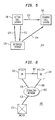
- FIG. 6 shows another embodiment of the switching network 100 according to the invention.
- the switch 101 receives signaling messages and forwards the signaling messages to the signaling network 102 via the transmission line 106.
- the signaling network 102 forwards the signaling messages to an active database 303.
- the switching network 100 also includes a standby database 304.
- the database 303 contains one or more call servers that receive signaling messages from the switch 101 and send back response messages when more data is required from the switch 101 or from another database in the switching network 100.
- the call server in the database 303 creates the call information for the call, copies the call information and forwards the call information to the standby database 304 over a transmission line 307.
- the transmission line 307 could be a dedicated wide area network, the signaling network 102 or a standard T1 or T3 line, for example, as long as the data transmission speed is sufficient to transmit the call information during the waiting period between sending a response and receiving the subsequent signaling message. If the active database 303 fails, the call can continue to be processed by the switching network 100 because the standby database 304 maintains up-to-date call information for the call.
- administrative servers 150 and 151 perform functions such as updating static information contained in the persistent memory 180 of the active call server 140. For example, if a user of the telecommunications network desires to change call routing for an 800 number on the weekends from Tulsa to Topeka, the administrative server 150, for example, would receive the request and would send a message to the active call server 140. The active call server 140 would then copy this information and forward it to the persistent memory 180 in the standby call server 141. In this way, the static data contained in the persistent memories 180 of the active call server 140 and the standby call server 141 are maintained current. Alternately, the administrative server 150 could send the same message to both the active call server 140 and the standby call server 141.
- FIG. 7 is a flowchart illustrating the operation of the database 103 of Figs. 3 and 4.
- the process begins in step S100.
- step S101 the interface server 120 receives a message.
- the message may be an initial signaling message or a subsequent message.
- step S102 the interface server 120 selects an active call server 140.
- step S103 the interface server 120 sends the message to the active call server 140.
- step S104 the interface server 120 sends the message to the active call server 140.
- step S104 the query processor 170 determines if the message is an initial signaling message or a subsequent message. If the message is the initial signaling message, the process moves to step S105. If the message is a subsequent message, the process moves to step S106. In step S105, the query processor formulates call information. The process then moves to step S108.
- step S106 the query processor determines if call information is present. If call information is present, the process moves to step S108. Otherwise, the process moves to step S107. In step S107, the active call server 140 aborts the call. The process then returns to step S100.
- step S108 the query processor 170 determines if more data is needed. If more data is needed, the process moves to step S110. Otherwise the process moves to step S109. In step S109, the query processor 170 sends a final instruction message to the interface server 120. The process then moves to step S113. In step S113, the query processor 170 determines if the call information was copied. If the call information was not copied, the process moves to step S100 and waits for messages. Otherwise, the process then moves to step S114. In step S114, the query processor 170 of the active call server 140 sends a message to the standby call server 141 to discard the copy of the call information. The process then moves to step S100 and waits for messages.
- step S110 the query processor 170 of the active call server 140 determines if a standby call server is available. If a standby call server is not available, the process moves to step S112. Otherwise, the process moves to step S111.
- step S111 the query processor 170 of the active call server 140 sends a current copy of the call information to the standby call server 141.
- step S112 the interface server 120 sends a request to the switch 101 or other network element for additional information.
- step S100 waits for messages.
- the query processor 170 is preferably implemented on a programmed general purpose computer. However, the query processor 170 can also be implemented on a special purpose computer, a programmed microprocessor or micro controller and peripheral integrated circuit elements and ASIC or other integrated circuit, additional signal processor, a hard wire electronic or logic circuit such as a discrete element circuit, a programmable logic device such as APLD, PLA, FPGA or PAL or the like. In general, any device capable of implementing a finite state machine for implementing a flowchart shown in Fig. 8 can be used to implement the query processor 170.
Landscapes
- Engineering & Computer Science (AREA)
- Computer Networks & Wireless Communication (AREA)
- Signal Processing (AREA)
- Telephonic Communication Services (AREA)
- Mobile Radio Communication Systems (AREA)
- Data Exchanges In Wide-Area Networks (AREA)
Applications Claiming Priority (2)
| Application Number | Priority Date | Filing Date | Title |
|---|---|---|---|
| US09/093,921 US6205557B1 (en) | 1998-06-09 | 1998-06-09 | Redundant call processing |
| US93921 | 1998-06-09 |
Publications (3)
| Publication Number | Publication Date |
|---|---|
| EP0964563A2 true EP0964563A2 (fr) | 1999-12-15 |
| EP0964563A3 EP0964563A3 (fr) | 2001-09-12 |
| EP0964563B1 EP0964563B1 (fr) | 2006-08-02 |
Family
ID=22241730
Family Applications (1)
| Application Number | Title | Priority Date | Filing Date |
|---|---|---|---|
| EP99304435A Expired - Lifetime EP0964563B1 (fr) | 1998-06-09 | 1999-06-08 | Traitement d'appel redondant |
Country Status (4)
| Country | Link |
|---|---|
| US (1) | US6205557B1 (fr) |
| EP (1) | EP0964563B1 (fr) |
| CA (1) | CA2273348C (fr) |
| DE (1) | DE69932567T2 (fr) |
Cited By (8)
| Publication number | Priority date | Publication date | Assignee | Title |
|---|---|---|---|---|
| EP1643731A1 (fr) * | 2004-09-30 | 2006-04-05 | Avaya Technology Corp. | Méthode et dispositif pour la fusion des composants des appels pendant une reconstruction d'appel |
| US7457249B2 (en) | 2005-01-04 | 2008-11-25 | Avaya, Inc. | Alternate routing of media connections within a single communications system across public or private network facilities |
| US7483369B2 (en) | 2003-09-30 | 2009-01-27 | Avaya Inc. | Method and apparatus for migrating to an alternate call controller |
| US7496056B2 (en) | 2005-01-04 | 2009-02-24 | Avaya Inc. | Conference connections using dynamic topology switching for IP and circuit-switched fabrics |
| US7564793B2 (en) | 2005-01-04 | 2009-07-21 | Avaya Inc. | In-band call association signaling for a single number destination |
| US7613106B2 (en) | 2005-01-04 | 2009-11-03 | Avaya Inc. | Dial plan transparency for fragmented networks |
| US8462637B1 (en) | 2005-01-04 | 2013-06-11 | Sheridan Ross P.C. | Dial plan routing for fragmented networks |
| EP3088397A1 (fr) | 2007-04-11 | 2016-11-02 | Canbas Co. Ltd. | Composés capables de supprimer le point de controle g2 du cycle cellulaire utile pour leur le traitement de cancer. |
Families Citing this family (23)
| Publication number | Priority date | Publication date | Assignee | Title |
|---|---|---|---|---|
| DE69927223T2 (de) * | 1998-09-08 | 2006-07-13 | Fujitsu Services Ltd. | Ausfallsicherheit eines Mehrrechnersystems |
| US6289001B1 (en) * | 1998-10-15 | 2001-09-11 | Telcordia Technologies, Inc. | System and method for ATM proxy signaling |
| US6370654B1 (en) * | 1998-12-17 | 2002-04-09 | Northern Telecom Limited | Method and apparatus to extend the fault-tolerant abilities of a node into a network |
| US6715099B1 (en) * | 1999-06-02 | 2004-03-30 | Nortel Networks Limited | High-availability architecture using high-speed pipes |
| US6327354B1 (en) * | 1999-08-17 | 2001-12-04 | Ameritech Corporation | Methods, systems, and articles for providing a family telecommunication service |
| US6785840B1 (en) * | 1999-08-31 | 2004-08-31 | Nortel Networks Limited | Call processor system and methods |
| US6522732B1 (en) * | 1999-12-06 | 2003-02-18 | Alcatel Usa Sourcing, L.P. | System and method of preserving stable calls during a split mode operation of telecommunications equipment |
| US6556672B1 (en) * | 1999-12-07 | 2003-04-29 | Intel Corporation | Fault tolerant voice processing system |
| US6618819B1 (en) * | 1999-12-23 | 2003-09-09 | Nortel Networks Limited | Sparing system and method to accommodate equipment failures in critical systems |
| US7733845B1 (en) * | 2000-05-25 | 2010-06-08 | Cisco Technology, Inc. | System and method for device registration replication in a communication network |
| US7653190B1 (en) | 2000-08-31 | 2010-01-26 | At&T Knowledge Ventures, L.P. | Methods, system and article for providing a family telecommunication service using an originating dual-tone multi-frequency trigger |
| US8019587B1 (en) * | 2000-09-06 | 2011-09-13 | Ciscotechnology, Inc. | Software upgrade of redundant network components |
| US7227927B1 (en) * | 2000-09-08 | 2007-06-05 | Tekelec | Scalable call processing node |
| US7533174B1 (en) * | 2000-09-29 | 2009-05-12 | Nortel Networks Limited | Media gateway connection information recovery |
| KR100434348B1 (ko) * | 2000-12-27 | 2004-06-04 | 엘지전자 주식회사 | 지능망 시스템의 특수자원 다중화 장치 및 그 제어방법 |
| US7945042B1 (en) * | 2000-12-29 | 2011-05-17 | Cisco Technology, Inc. | Method for switching active calls |
| US7257629B2 (en) * | 2001-09-27 | 2007-08-14 | Siemens Communications, Inc. | Method and apparatus for providing back-up capability in a communication system |
| US7978598B1 (en) * | 2002-03-01 | 2011-07-12 | Cisco Technology, Inc. | Connection replication |
| US7532568B1 (en) * | 2002-07-09 | 2009-05-12 | Nortel Networks Limited | Geographic redundancy for call servers in a cellular system based on a bearer-independent core network |
| US20040103125A1 (en) * | 2002-11-21 | 2004-05-27 | Adc Dsl Systems, Inc. | Group submission of edits for rules checking |
| US20060271663A1 (en) * | 2005-05-31 | 2006-11-30 | Fabio Barillari | A Fault-tolerant Distributed Data Processing System |
| US8295459B2 (en) * | 2006-08-24 | 2012-10-23 | Verisign, Inc. | System and method for dynamically partitioning context servers |
| US8019063B2 (en) * | 2006-08-24 | 2011-09-13 | Verisign, Inc. | System and method for providing high reliability network |
Family Cites Families (11)
| Publication number | Priority date | Publication date | Assignee | Title |
|---|---|---|---|---|
| NL7202501A (fr) * | 1972-02-25 | 1973-08-28 | ||
| GB2273851A (en) * | 1992-12-22 | 1994-06-29 | Ibm | Call routing in switched digital networks |
| US5590181A (en) * | 1993-10-15 | 1996-12-31 | Link Usa Corporation | Call-processing system and method |
| US5592530A (en) * | 1995-01-25 | 1997-01-07 | Inet, Inc. | Telephone switch dual monitors |
| US5848128A (en) * | 1996-02-29 | 1998-12-08 | Lucent Technologies Inc. | Telecommunications call preservation in the presence of control failure |
| US5736933A (en) * | 1996-03-04 | 1998-04-07 | Motorola, Inc. | Method and apparatus for providing redundancy in a communication network |
| JPH1013532A (ja) * | 1996-06-19 | 1998-01-16 | Fujitsu Ltd | インテリジェントネットワークにおける通信状態管理方式および方法 |
| US5875242A (en) * | 1996-07-26 | 1999-02-23 | Glaser; Lawrence F. | Telecommunications installation and management system and method |
| US5933474A (en) * | 1996-12-24 | 1999-08-03 | Lucent Technologies Inc. | Telecommunications call preservation in the presence of control failure and high processing load |
| US5974114A (en) * | 1997-09-25 | 1999-10-26 | At&T Corp | Method and apparatus for fault tolerant call processing |
| US6016334A (en) * | 1997-10-29 | 2000-01-18 | Alcatel Usa Sourcing, L.P. | Method and system for automatically verifying provisioning of telecommunications services |
-
1998
- 1998-06-09 US US09/093,921 patent/US6205557B1/en not_active Expired - Lifetime
-
1999
- 1999-05-31 CA CA002273348A patent/CA2273348C/fr not_active Expired - Fee Related
- 1999-06-08 DE DE69932567T patent/DE69932567T2/de not_active Expired - Lifetime
- 1999-06-08 EP EP99304435A patent/EP0964563B1/fr not_active Expired - Lifetime
Cited By (10)
| Publication number | Priority date | Publication date | Assignee | Title |
|---|---|---|---|---|
| US7483369B2 (en) | 2003-09-30 | 2009-01-27 | Avaya Inc. | Method and apparatus for migrating to an alternate call controller |
| EP1643731A1 (fr) * | 2004-09-30 | 2006-04-05 | Avaya Technology Corp. | Méthode et dispositif pour la fusion des composants des appels pendant une reconstruction d'appel |
| US7366110B2 (en) | 2004-09-30 | 2008-04-29 | Avaya Technology Corp. | Method and apparatus for merging call components during call reconstruction |
| US7738360B2 (en) | 2004-09-30 | 2010-06-15 | Avaya Inc. | Method and apparatus for merging call components during call reconstruction |
| US7457249B2 (en) | 2005-01-04 | 2008-11-25 | Avaya, Inc. | Alternate routing of media connections within a single communications system across public or private network facilities |
| US7496056B2 (en) | 2005-01-04 | 2009-02-24 | Avaya Inc. | Conference connections using dynamic topology switching for IP and circuit-switched fabrics |
| US7564793B2 (en) | 2005-01-04 | 2009-07-21 | Avaya Inc. | In-band call association signaling for a single number destination |
| US7613106B2 (en) | 2005-01-04 | 2009-11-03 | Avaya Inc. | Dial plan transparency for fragmented networks |
| US8462637B1 (en) | 2005-01-04 | 2013-06-11 | Sheridan Ross P.C. | Dial plan routing for fragmented networks |
| EP3088397A1 (fr) | 2007-04-11 | 2016-11-02 | Canbas Co. Ltd. | Composés capables de supprimer le point de controle g2 du cycle cellulaire utile pour leur le traitement de cancer. |
Also Published As
| Publication number | Publication date |
|---|---|
| DE69932567D1 (de) | 2006-09-14 |
| CA2273348A1 (fr) | 1999-12-09 |
| EP0964563B1 (fr) | 2006-08-02 |
| CA2273348C (fr) | 2003-05-13 |
| DE69932567T2 (de) | 2007-08-09 |
| US6205557B1 (en) | 2001-03-20 |
| EP0964563A3 (fr) | 2001-09-12 |
Similar Documents
| Publication | Publication Date | Title |
|---|---|---|
| US6205557B1 (en) | Redundant call processing | |
| US5883939A (en) | Distributed architecture for an intelligent networking coprocessor | |
| US5623532A (en) | Hardware and data redundant architecture for nodes in a communications system | |
| KR100194159B1 (ko) | 무교환 자동 전화 착신 분배 시스템 및 자동 호출 전송 방법 | |
| US5848128A (en) | Telecommunications call preservation in the presence of control failure | |
| US7194078B2 (en) | Network redirection control routing | |
| US6111852A (en) | Methods and systems for emergency routing restoration | |
| JPH1051549A (ja) | 共同制御を伴うホームacd代行者網における作業 | |
| JP3407016B2 (ja) | 網管理システム | |
| EP1040684A1 (fr) | Procede permettant de conserver la fiabilite d'un reseau de service | |
| US6501839B1 (en) | Method and apparatus for equitable call delivery | |
| KR960016654B1 (ko) | 지능망 서비스 데이타의 지역 이중화된 지능망 서비스 제어용 트랜잭션 처리 시스팀 및 지역 이중화 관리를 위한 계층 제어 방법 | |
| KR970002739B1 (ko) | 전전자 교환기에서 No.7 신호방식 사용자부와 메시지 전달부간 정합 방법 | |
| KR910006455B1 (ko) | 가입자망간 접속장치의 계층 3에서 데이터 링크상태 관리방법 | |
| MXPA97005122A (en) | Redundant architecture of hardware and paranod data in a communication system | |
| KR930010917B1 (ko) | CCITT No. 7 신호방식의 신호연결 제어부간 동작대기 방법에 의한 신호망 관련데이터 일치방법 | |
| JP2645134B2 (ja) | 復旧信号リンクへのメッセージ送出制御方式 | |
| JP3317756B2 (ja) | サービス制御階層と伝達制御階層間のインタフェース方式 | |
| Lin et al. | FAX broadcasting system-The software aspects | |
| JPH10150469A (ja) | フレームリレー・バックアップ・システム及びバックアップ方法 | |
| JPH05336166A (ja) | 通信無中断形ファイル更新方法 | |
| KR19980047013A (ko) | 지역 이중화된 지능망 서비스 제어 시스팀의 서비스 데이터 온라인 변경방법 | |
| CN110233761A (zh) | 一种基于中继服务器的冗余切换方法及系统 | |
| JPH06350694A (ja) | パケットハンドラ共有制御装置 | |
| JPH04160965A (ja) | 交換網における在席情報の更新方法 |
Legal Events
| Date | Code | Title | Description |
|---|---|---|---|
| PUAI | Public reference made under article 153(3) epc to a published international application that has entered the european phase |
Free format text: ORIGINAL CODE: 0009012 |
|
| AK | Designated contracting states |
Kind code of ref document: A2 Designated state(s): AT BE CH CY DE DK ES FI FR GB GR IE IT LI LU MC NL PT SE Kind code of ref document: A2 Designated state(s): DE FR GB |
|
| AX | Request for extension of the european patent |
Free format text: AL;LT;LV;MK;RO;SI |
|
| PUAL | Search report despatched |
Free format text: ORIGINAL CODE: 0009013 |
|
| AK | Designated contracting states |
Kind code of ref document: A3 Designated state(s): AT BE CH CY DE DK ES FI FR GB GR IE IT LI LU MC NL PT SE |
|
| AX | Request for extension of the european patent |
Free format text: AL;LT;LV;MK;RO;SI |
|
| 17P | Request for examination filed |
Effective date: 20011130 |
|
| AKX | Designation fees paid |
Free format text: DE FR GB |
|
| GRAP | Despatch of communication of intention to grant a patent |
Free format text: ORIGINAL CODE: EPIDOSNIGR1 |
|
| GRAS | Grant fee paid |
Free format text: ORIGINAL CODE: EPIDOSNIGR3 |
|
| GRAA | (expected) grant |
Free format text: ORIGINAL CODE: 0009210 |
|
| AK | Designated contracting states |
Kind code of ref document: B1 Designated state(s): DE FR GB |
|
| REG | Reference to a national code |
Ref country code: GB Ref legal event code: FG4D |
|
| REF | Corresponds to: |
Ref document number: 69932567 Country of ref document: DE Date of ref document: 20060914 Kind code of ref document: P |
|
| ET | Fr: translation filed | ||
| PLBE | No opposition filed within time limit |
Free format text: ORIGINAL CODE: 0009261 |
|
| STAA | Information on the status of an ep patent application or granted ep patent |
Free format text: STATUS: NO OPPOSITION FILED WITHIN TIME LIMIT |
|
| 26N | No opposition filed |
Effective date: 20070503 |
|
| PGFP | Annual fee paid to national office [announced via postgrant information from national office to epo] |
Ref country code: GB Payment date: 20140527 Year of fee payment: 16 |
|
| PGFP | Annual fee paid to national office [announced via postgrant information from national office to epo] |
Ref country code: FR Payment date: 20140527 Year of fee payment: 16 |
|
| PGFP | Annual fee paid to national office [announced via postgrant information from national office to epo] |
Ref country code: DE Payment date: 20140630 Year of fee payment: 16 |
|
| REG | Reference to a national code |
Ref country code: DE Ref legal event code: R119 Ref document number: 69932567 Country of ref document: DE |
|
| GBPC | Gb: european patent ceased through non-payment of renewal fee |
Effective date: 20150608 |
|
| REG | Reference to a national code |
Ref country code: FR Ref legal event code: ST Effective date: 20160229 |
|
| PG25 | Lapsed in a contracting state [announced via postgrant information from national office to epo] |
Ref country code: GB Free format text: LAPSE BECAUSE OF NON-PAYMENT OF DUE FEES Effective date: 20150608 Ref country code: DE Free format text: LAPSE BECAUSE OF NON-PAYMENT OF DUE FEES Effective date: 20160101 |
|
| PG25 | Lapsed in a contracting state [announced via postgrant information from national office to epo] |
Ref country code: FR Free format text: LAPSE BECAUSE OF NON-PAYMENT OF DUE FEES Effective date: 20150630 |