EP0964728B1 - Dispositif de freinage - Google Patents
Dispositif de freinage Download PDFInfo
- Publication number
- EP0964728B1 EP0964728B1 EP98905139A EP98905139A EP0964728B1 EP 0964728 B1 EP0964728 B1 EP 0964728B1 EP 98905139 A EP98905139 A EP 98905139A EP 98905139 A EP98905139 A EP 98905139A EP 0964728 B1 EP0964728 B1 EP 0964728B1
- Authority
- EP
- European Patent Office
- Prior art keywords
- brake
- arm
- brake slide
- roller skate
- slide
- Prior art date
- Legal status (The legal status is an assumption and is not a legal conclusion. Google has not performed a legal analysis and makes no representation as to the accuracy of the status listed.)
- Expired - Lifetime
Links
- 230000033001 locomotion Effects 0.000 claims description 23
- 238000006073 displacement reaction Methods 0.000 claims description 4
- 238000005096 rolling process Methods 0.000 claims description 4
- 230000000284 resting effect Effects 0.000 claims 1
- 230000000694 effects Effects 0.000 description 21
- 230000007246 mechanism Effects 0.000 description 11
- 230000005540 biological transmission Effects 0.000 description 10
- 238000005299 abrasion Methods 0.000 description 6
- 238000013459 approach Methods 0.000 description 5
- 210000002683 foot Anatomy 0.000 description 4
- 210000003423 ankle Anatomy 0.000 description 3
- 230000008901 benefit Effects 0.000 description 3
- 230000009194 climbing Effects 0.000 description 3
- 238000013016 damping Methods 0.000 description 3
- 238000003860 storage Methods 0.000 description 3
- 230000001960 triggered effect Effects 0.000 description 3
- 238000010276 construction Methods 0.000 description 2
- 238000005516 engineering process Methods 0.000 description 2
- 230000006872 improvement Effects 0.000 description 2
- 238000004519 manufacturing process Methods 0.000 description 2
- 230000004044 response Effects 0.000 description 2
- 238000012549 training Methods 0.000 description 2
- 230000000903 blocking effect Effects 0.000 description 1
- 230000008859 change Effects 0.000 description 1
- 238000006243 chemical reaction Methods 0.000 description 1
- 230000006378 damage Effects 0.000 description 1
- 230000007812 deficiency Effects 0.000 description 1
- 230000006735 deficit Effects 0.000 description 1
- 238000012423 maintenance Methods 0.000 description 1
- 238000000034 method Methods 0.000 description 1
- 230000000414 obstructive effect Effects 0.000 description 1
- 239000004033 plastic Substances 0.000 description 1
- 230000008569 process Effects 0.000 description 1
- 230000002441 reversible effect Effects 0.000 description 1
- 238000012552 review Methods 0.000 description 1
- 239000007787 solid Substances 0.000 description 1
- 238000012360 testing method Methods 0.000 description 1
Images




Classifications
-
- A—HUMAN NECESSITIES
- A63—SPORTS; GAMES; AMUSEMENTS
- A63C—SKATES; SKIS; ROLLER SKATES; DESIGN OR LAYOUT OF COURTS, RINKS OR THE LIKE
- A63C17/00—Roller skates; Skate-boards
- A63C17/14—Roller skates; Skate-boards with brakes, e.g. toe stoppers, freewheel roller clutches
- A63C17/1409—Roller skates; Skate-boards with brakes, e.g. toe stoppers, freewheel roller clutches contacting one or more of the wheels
- A63C17/1427—Roller skates; Skate-boards with brakes, e.g. toe stoppers, freewheel roller clutches contacting one or more of the wheels the brake contacting other wheel associated surfaces, e.g. hubs, brake discs or wheel flanks
-
- A—HUMAN NECESSITIES
- A63—SPORTS; GAMES; AMUSEMENTS
- A63C—SKATES; SKIS; ROLLER SKATES; DESIGN OR LAYOUT OF COURTS, RINKS OR THE LIKE
- A63C17/00—Roller skates; Skate-boards
- A63C17/04—Roller skates; Skate-boards with wheels arranged otherwise than in two pairs
- A63C17/06—Roller skates; Skate-boards with wheels arranged otherwise than in two pairs single-track type
-
- A—HUMAN NECESSITIES
- A63—SPORTS; GAMES; AMUSEMENTS
- A63C—SKATES; SKIS; ROLLER SKATES; DESIGN OR LAYOUT OF COURTS, RINKS OR THE LIKE
- A63C17/00—Roller skates; Skate-boards
- A63C17/14—Roller skates; Skate-boards with brakes, e.g. toe stoppers, freewheel roller clutches
- A63C2017/1481—Leg or ankle operated
Definitions
- the invention relates to a roller skate (as described in GB 609 453), preferably one behind the other on a carrier single-track, arranged roles, a shoe part, one opposite the shoe part swiveling shoe upper or shoe neck, one over the shoe upper or shoe neck operable brake lever, and one over the brake lever in the longitudinal direction of the carrier movable brake slider acting on one or more of the rollers, wherein the wearer is connected to the shoe part of the roller skate on its underside or is connectable, and the brake pivot lever at least from an actuating arm and at least one in operative contact with the brake slide, preferably butt contact, standing attack arm is formed, the pivot axis of the brake pivot lever on the carrier or on the shoe part of the roller skate is arranged, and the free end of the Actuating arm can be pivoted by movement of the shoe upper or shoe neck, and wherein the brake slide is substantially in line with the axis of rotation of the rollers spanned plane is displaceable.
- Braking devices for single track roller skates are for the safety and comfort of the User of great importance.
- braking devices are also for everyone important to other participants in the traffic situation, because their safety of it is affected. Even so, a large number of known braking devices already exist, the previous solutions are not a really satisfactory situation because they either are ineffective in braking effect, an unstable posture to operate require, they can be triggered unintentionally because if the rollers are braked cause excessive abrasion or because they are often from the Production-technical point of view considered too complicated and therefore too expensive are.
- roller skates there are various braking systems, most of which are based on the Running pad, i.e. on the floor, but also partially on the rollers.
- the present invention is concerned exclusively with brake systems that are on the rollers or if necessary, wheels act, the braking process then already having an effect, if only one of the rollers is braked.
- the braking device on at least two or Allowing three roles to take effect, although it is usually an advantage not to have the last role to brake, since many roller skaters use it from the braking systems still in use are used to lifting roller skates when braking, and consequently only braking would have an effect on the last roll, especially under an unfavorable because unstable posture.
- the result of such braking is then very often undesirable strong abrasion of this role, which subsequently quickly becomes inoperable is caused by a significant impairment of the entire driving and Braking properties of the single-track roller skates can be conditional.
- WO-A-96/24414 (Burian, Ribarits) discloses a transmission mechanism which the pivoting of the shaft for actuating a braking device on a Variety of roles can act, redirects.
- this braking device only includes the Possibility to use shoes, the shaft of which is pivoted to the shell are connected, or in which at least a sleeve-like stiffening on the shaft Purpose of power transmission of the shaft movement to the transmission member is provided.
- the slide is articulated in the direction of travel below the roller axis level, that is it Braking result from the reverse effect, namely the slider of which itself rotating rollers or wheels pushed around a constantly renewing stretch is significantly restricted, which in turn is the intention of a well-working Brake device contradicts.
- the guidance of the brake valve at the pivot axis height is also for reasons of Strength and reliability of the braking system is important because of the stability of the The frame is particularly high, especially at the height of the axle, thanks to the usually bolted axles is.
- GB-A-609 453 is a braking device for a roller skate with a front and two side-by-side, rear roles described, in which the Braking by means of a brake pusher exactly in the direction of the roller rotation axes spanned plane takes place, the displacement of the brake valve using the Attack arm of a brake pivot lever happens, the pivot axis on one Carrier surface of the roller skate is arranged.
- the actuating arm of the brake lever is by a forward movement of the shoe neck of the Roller skate body used shoe pivoted. Swivel lever and shoe neck are linked together by a strap.
- the object of the invention is to maintain the roller skate as easy as possible and one enable the easiest possible role swap.
- Another object is to provide a braking device with which safe braking is made possible for the roller skater. Furthermore, it is a task, if possible to achieve even load on the roller skate during braking.
- Another object of the invention is therefore to provide a braking device with which suitable dosage of the applied braking force can be achieved.
- Another object of the invention is therefore to provide a braking device with the easy walking and climbing with roller skates is possible.
- pivot axis from two or several aligned pivot bearings is formed. This allows the pivoting storage also provided on opposite sides Swivel bearings can be realized so that no continuous axis of rotation is required.
- the brake slide is formed from a frame that each in the area of one or more roles, preferably except for the rearmost role of the Roller skate, has at least one contact surface which when the Brake lever from an exempted position to a braking position in the system the side roller surfaces adjacent to or on the rolling surfaces attached braking surfaces, e.g. Brake discs, can be brought or are.
- actuating arm and the attack arm rigid in the region of the pivot axis of the brake pivot lever are interconnected, which is a very simple way of Power transmission from the shoe upper or shoe neck to the brake slide results.
- a regardless of Low attack and from the actuating arm, preferably about the pivot axis of the Brake pivot lever, pivotable actuating arm is provided with its free end bears against the displaceable brake slide and preferably via an adjusting element an adjusting screw, is in active contact with the attack arm, so that at one Swiveling movement of the attack arm this the free end of the actuating arm against the sliding brake slide presses.
- Threshold of the braking device according to the invention especially at one point cannot cause a hindrance or danger to the roller skate user.
- attack arm is about half as long as that Actuating arm is, because in this case a particularly advantageous power transmission and Setting option is given.
- a regardless of Low attack and from the actuating arm, preferably about the pivot axis of the Brake pivot lever, pivotable two-armed actuating arm is provided with his a free end is in abutting contact with one end of the sliding brake valve, and in operative contact with an adjusting element, preferably an adjusting screw the attack arm stands and at the second free end of an eccentric head Eccentric pivot lever is articulated, which by pivoting into its eccentric position Low attack with its eccentric head permanently in the braking position of the brake valve holds.
- the attack arm along its Longitudinal extension of a large number of spaced-apart, open-edge incisions exhibit.
- the actuating arm two hinged parts is formed, the end of one Actuating arm part is extended beyond the hinge point and with the end of Arm extension on an elastic molded onto the other operating arm part Tongue rests, which is initially elastically deformable when the actuating arm is pivoted, before the adhesion between the actuating arm parts is established.
- Tongue rests, which is initially elastically deformable when the actuating arm is pivoted, before the adhesion between the actuating arm parts is established.
- the brake valve is also intended for the purpose of determining the roles stuck on the Rolls can be pressed. As for the mechanism that does this a variety of conditions must be taken into account, which ensure a reliable, should allow economically efficient and user-friendly solution. The same applies to the Adjustment of the trigger lever.
- the conditions to be taken into account are essentially the following:
- the pressure on the brake valve must be so tight that the rollers are reliably clamped between the contact point and the roller axis. This criterion requires effective leverage of the force used.
- the lever that applies the pressure must be in the position in which it locks Stuck immovably, otherwise an unintentional detachment can occur, causing the e.g. climbing skaters would be in danger.
- the locking device should be effective for different reel sizes and shapes, so that not with Use a different type of roller of the brake valve or other parts exchanged Need to become. This also applies to the adjustability of the release lever. This must also if possible include a sufficiently large scope.
- an adjustment device also makes an optimal one Adjustment of the trigger lever for the purpose of adapting to different strengths of the lower leg and an exact adjustability of the trigger time.
- an additional brake slide independent of the brake slide preferably two wedge-shaped contact surfaces arranged in the area of the rearmost roller is, and that both the brake valve and the auxiliary brake valve via one Swivel levers are displaceable, so that in the eccentric position of the swivel lever Contact surfaces of the auxiliary brake valve and the contact surfaces of the brake valve are permanently held in the braking position.
- the Brake slide and the additional brake slide are arranged displaceably in one plane. This enables a very simple sliding mechanism for the locking of the rollers apply.
- an eccentric vane by one, preferably parallel to the Roller pivot axes extending pivot axis is pivotally arranged, in which Eccentric position of the eccentric pivoting lever, the eccentric vane the mutual Distance between the brake slide and the additional brake slide, enlarged and in the free position of the eccentric pivot lever reduces the mutual distance.
- the eccentric wing disc enables the rollers to be locked very effectively in the braking position.
- the eccentric vane can have straight snap-in areas in their eccentric position. This will create a automatic slipping of the cam disc from the fixed braking position of the Rolling prevented.
- Actuating pin is pivotally connected to the head of the eccentric pivoting lever, wherein in the eccentric position of the eccentric pivot lever against the wedge-shaped lugs opposing contact surfaces of the brake slide and the additional brake slide are pressed, so that they are kept permanently in the braking position.
- the wedge-shaped contact surfaces allow a particularly effective locking of the rollers in their braked positions.
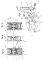
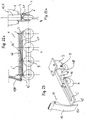
- FIG. 1 shows a braking device for a single-track roller skate with a carrier 3 one behind the other rollers 4.
- the braking device according to the invention is in The following only described for single-track roller skates, it prepares for the specialist still no problems, the principle of the invention also two or more lane roller skates apply.
- the roller skate usually consists of a shoe part in which the foot of the There is room for roller skaters and a shoe upper 2 or shoe neck 2 '.
- the latter Conceptual distinction is intended to clarify that there is no difference for the invention makes whether an articulated to the shoe part 1 shoe upper 2 (Fig.2) or only Shoe neck 2 'flexibly connected to the shoe part 1, e.g. in a so-called “Soft boot” is the case, used, in both cases the invention is full application-capable.
- the invention Braking device can either be fixed to the bottom of the shoe part or be connectable with this.
- the user can, for example, in the go around the soft, flexible shoe and, if necessary, the wearer with the wheels and the braking device according to the invention on the underside of the shoe e.g. by an appropriate one Set binding.
- rollers arranged on the carrier can either consist of a stable core with a Solid rubber or plastic sheathing are formed, instead of the rollers Wheels with air hose and tires and other variants can be used.
- the braking device according to the invention is operated via a brake pivot lever 11, 12 actuated, the pivoting movement of which is displaceable in the longitudinal direction of the carrier, is transferred to one or more of the rollers acting brake slider.
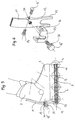
- the brake pivot lever is in Fig.1 and Fig.2 from an actuating arm 11 and one with the brake valve 6 in abrupt contact arm 12 formed, the Pivot axis 13 of the brake pivot lever 11, 12 in FIGS. 1 and 2 on the carrier 3 is arranged.
- the pivot axis can also on the shoe part 1 of the roller skate be arranged, the storage of the pivot axis in every conceivable form can happen.
- 1 is a fork-shaped on the rear part of the carrier 3 Swivel bracket attached, which receives the pivot axis 13 between the legs and supports while the pivot axis 13 is supported in the exemplary embodiment according to FIG happens directly on the carrier 3.
- the pivot axis 13 runs parallel for reasons of symmetry to the axes of rotation 5 of the rollers 4 and can be arranged in alignment from two or more Be pivot bearings formed.
- FIG. 1 In Fig.1 and Fig.2 two different adjustment options are shown, all for Embodiments can be used. So is in the embodiment of FIG. 1 at the free An adjusting screw 16 with a screw shaft 43 ends the attack arm 12 provided that is rotatable in a thread of the attack arm 12 so that the The actuation threshold from which a braking effect begins is adjustable.
- the brake slide is formed from a frame 6, each in the area of the rollers 4 has at least one contact surface 7 which, when the brake pivot lever 11 is actuated, 12 from an exempted position to a braking position in contact with the oblique side Roll surfaces or brake surfaces attached to them, e.g. Brake discs 39 (Fig.3a, 3b, 3c), is or can be brought.
- the frame-like structure of the brake slide 6 is shown in FIG.
- FIG. 11 An embodiment is preferred in which rear roller 4 of the roller skate no contact surfaces 7 are provided. Above all, this has meaning because otherwise many users are used to the conventional roller skates the rearmost role would brake twice. With a swiveling movement of the shoe upper 2 or the shoe neck 2 'against the direction of travel, the brake valve 6 is thus over the Brake pivot lever 11, 12 moved in the direction of travel, so that the contact surfaces 7 against the corresponding surfaces are pressed on the rollers 4 and thereby a braking effect arises. Due to the brake slide 6 acting on several rollers 4, one becomes enables very even braking.
- the rollers 4 can be attached to their sides by elements 39 for braking the contact surfaces 7 are reinforced, so that abrasion or wear of the rollers itself can be prevented.
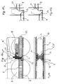
- plug-on elements 39 are provided in FIGS. 3b and 3c, which can be plugged onto the sides of the rollers 4 and together with these on the Axes of rotation 5 are stored.
- the plug-on elements 39 face the contact surfaces 7 of the Brake spool opposite extensions 40, which move with the contact surfaces of the brake valve are brought into contact and achieve a braking effect, without the roller 4 itself being rubbed off.
- the extensions 40 'of the push-on elements 39 can be normal to the Axes of rotation 5 may be designed to run, the front ends of these extensions being act on the contact surfaces 7 opposite surfaces. Accordingly, they are Contact surfaces 7 arranged parallel to the axes of rotation 5.
- the actuating arm 11 and the attack arm 12 of the exemplary embodiments according to FIGS. 1 and 2 are rigidly connected to each other in the region of the pivot axis 13 of the brake pivot lever. But it can both the actuating arm 11 and the arm 12 in several parts be formed and the connection between these can also be articulated, provided by means of a driving element in the event of impact contact with the brake slide 6, a leverage effect is achieved.
- the brake pivot lever is in the form of a bracket 11, 12, wherein the pivot axis 13 through the side surfaces of the bracket 11, 12th runs.
- the storage itself takes place via bearing pins 13 'arranged on both sides.
- the Low attack does not act directly on the brake slide 6 but stands over one fork-shaped actuating arm 20 which is pivotable about the pivot axis 13 and on which displaceable brake slide 6 is in operative contact with this.
- the Actuation threshold for the response of the brake slide 6 can be via a Adjustment screw 16 '' 'are adjusted, the end of which against a crosspiece 24 of the Adjustment element 20 is present.
- the arm 12 When the arm 12 pivots, it presses Via the adjusting screw 16 '' 'the free end of the actuating arm 20, which here consists of two legs 43 is formed, against the sliding brake slide 6 or against the two Frame parts of the brake slide 6, which with the legs 43 of the actuating element 20 in Butt contact.
- the attack arm 12 is about half as much in this embodiment long as the actuator arm 20 itself.
- FIG. 5 and 6 show an exemplary embodiment in which the bearing axis 13 is slidably held on the shoe part 1.
- the pivot axis 13 is now in via the adjusting screw 16 " the elongated holes 36 from a position close to the shoe part 1 into an opposite, far position slidable, so that the response threshold of the braking device is correspondingly variable.
- the legs 43 of the arm 12 press in this Embodiment when operating the actuating lever 11 directly against the frame ends the brake valve 6.
- the carrier 3 is composed of two parts, in each of which on the inside two longitudinal grooves 8 are excluded, in which the frame of the Brake slide 6 is slidably held.
- the bow-shaped brake pivot lever 11, 12 is Can be pivoted via a bearing screw 13 screwed to the carrier 3, on the same
- the pivot arm is also mounted on the actuating arm 20, which with its two legs 43 in Butt contact with the frame ends of the brake slide 6.
- the contact surfaces 7 are each provided at the rear ends of the spaced frame openings, in which the rollers 4 are rotatably mounted, which are not shown in Fig. 7.
- the Roller axes of rotation run through the holes 5 in the two parts of the carrier 3.
- Der Brake slide 6 acts in this embodiment only on the front rollers 4, while the rearmost roller 4, not shown, is not braked.
- a pivot lever 14 ' is provided, which on the outside of the invention Braking device is arranged pivotable about an axis of rotation 15 '. Rotatable with the The pivot axis 15 'is connected to a locking head 22 "', two on the outer sides Eccentric discs 90 are formed, which when the pivot lever 14 'is actuated Brake slide 6 independent of the brake lever 11, 12 from its exempted Position moves to the braking position, whereby the (not shown) rollers against a Rotation are secured.
- the profiled, central part of the locking head 2 '' ' pressed against the rearmost (not shown) roller 4 so that this also on a Rotation is prevented. So that all roles 4 are fixed, which is a noticeable Facilitation of movement outside of normal driving movement when occurring, e.g. Climbing stairs with the roller skates results.
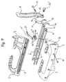
- a further possibility of locking the rollers 4 according to FIGS. 8a and 8b is to to provide a pivotable eccentric pivot lever 14 with an eccentric head 22, the eccentric pivot lever pivoted into its eccentric position Actuating arm 11 with its eccentric head 22 permanently in the braking position of the Brake slide 6 holds.
- one is independent of the attack arm 12 and from the actuating arm 11 pivotable about the pivot axis 13 of the brake pivot lever two-armed actuating arm 20, 21 provided with one free end in abutting contact with one end of the sliding brake valve 6, and the one Adjusting screw 16 "'is in active contact with the attack arm 12.
- the eccentric head 22 of the eccentric pivot lever 14 is articulated at the end of the actuating arm 20, 21, which by pivoting into its eccentric position, the actuating arm 20 with its eccentric head 22 holds permanently in the braking position of the brake slide 6.
- the eccentric lever 14 is by folding up from the position shown in Fig. 8a and 8b in its eccentric position brought.
- FIG. 9 shows a variant of the invention, in which the eccentric lever 14 also the actuating arm 20 presses against the rearmost roller via a contact surface 9 'and thus in its eccentric position also defines the rearmost role.
- FIG. 10 Another variant of a locking possibility according to FIG. 10 is that one of the brake slide 6 independent auxiliary brake slide with two wedge-shaped Contact surfaces 7 'is arranged in the area of the rearmost roller.
- the brake valve 6 and the additional brake slides are slidably arranged in one plane and are over one by means of a pivot lever 14 'about a pivotable eccentric vane disc 22' displaceable, the pivot axis of which runs parallel to the roller rotation axes 5.
- the pivot lever 14 ' is provided with a pressure surface 27.
- the Eccentric position of the pivot lever 14 ' are the contact surfaces 7' of the Additional brake valve and the contact surfaces 7 of the brake valve 6 permanently in the Braking position held, whereby all roles are fixed and a problem-free gradual Moving is possible.
- FIG. 11 shows a latching device 32, 30 ', via which the Swivel lever 14 'is adjustable in position and can be automatically locked. To the Leg 44 must be released with the fingers using the latched pivot lever position be pressed together so that the latch is released and the pivot lever in his optional position can be returned.
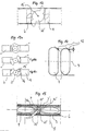
- an eccentric vane 22 ', 22 "around a pivot axis 15 ' is pivotally arranged, in the eccentric position of the Swivel lever 14 'the eccentric vane 22', 22 "the mutual distance between the brake slide 6 and the additional brake slide 9 enlarged and in the free position of the pivot lever 14 'reduces the mutual distance.
- the eccentric position of the eccentric vane disc 22 ' is in dashed lines in FIG. 12 shown, which can be reached via a rounding of the eccentric wings.
- the eccentric vane 22 ' has straight snap-in areas in its eccentric position on.
- Fig. 13a is the free position of the eccentric vane 22 ', in Fig. 13b a first Snap position and shown in Fig.14b a second snap position, the two for Different embodiments of roles (see Fig. 14) defined locking positions define.
- an adjusting mandrel 23 with wedge-shaped approaches transverse to Direction of displacement of the brake slide 6 or the additional brake slide 9 is displaceable guided.
- the adjusting mandrel 23 is via a head 22 "'of the eccentric pivot lever 14' articulated. In the eccentric position of the eccentric pivot lever 14 ' wedge-shaped approaches against opposing contact surfaces 25 of the brake slide 6 and the Additional brake slide 9 pressed so that they are permanently held in the braking position.
- Fig. 17a shows the free position of the eccentric lever 14 'and Fig. 17b the Contact position, in which both the brake slide 6 and the additional brake slide 9 themselves are in their determined position.
- the Additional brake slide 9 arranged offset in height from the brake slide 6, so that the Contact surfaces 7'd of the additional brake slide on an axially offset area of the rearmost Roll 4 act.
- a brake pivot lever which has a damping effect on the The upper part of the upper shows the force exerted.
- the Actuating arm formed from two articulated parts 11, 11 ', wherein the end of an actuating arm part 11 'is extended beyond the hinge point and with the end of the arm extension 11 "on one to the other actuating arm part molded elastic tongue 17 abuts.
- Tongue 17 is first elastically deformable before the frictional connection between the Actuating arm parts is made, so that there is an overall braking movement dampening movement results.
- the actuating arm 11 according to FIG. 21 has a large number along its longitudinal extent spaced apart, open-edge incisions 19, which this an elastic Behavior gives that a dampening effect on that of the shoe upper or shoe neck exerted force causes.
- FIG Sliding element 6 ' is provided with a wedge-shaped end 46 and offset in height from the Axes of rotation of the rollers 4 is guided.
- a brake slide 47 has a profile with contact surfaces 7 'on that from a position above the rollers to the obliquely lateral Braking surfaces of the rollers is slidable. Now the sliding element 6 'through Swiveling the attack arm 12 with its wedge-shaped surface 46 against the opposed wedge-shaped surface 46 'of the brake slide 47 pressed, so the Contact surfaces 7 'pressed from above against the inclined lateral contact surfaces of the rollers 4 and a corresponding braking effect sets in.
- FIG Attack arm 12 a sliding element 6 'with wedge-shaped end faces against both sides of a Brake clip 48 which extends along the rollers 4 and these in their upper regions partially surrounded, molded wedges 46 'is pressed, which is a lateral pressure of the Brake clip 48 causes with their contact surfaces against the oblique lateral roller surfaces.
Landscapes
- Braking Arrangements (AREA)
- Footwear And Its Accessory, Manufacturing Method And Apparatuses (AREA)
Abstract
Claims (14)
- Patin à roulettes avec un support (3), des roulettes (4) disposées les unes derrière les autres, de préférence sur un seul rang, une partie formant chaussure (1), une tige de chaussure (2) ou un montant de chaussure (2') pouvant pivoter par rapport à la partie formant chaussure (1), un levier de freinage pivotant pouvant être actionné par l'intermédiaire de la tige de chaussure (2) ou du montant de chaussure (2') et une coulisse de freinage (6) pouvant être déplacée par le levier de freinage pivotant dans le sens longitudinal du support (3) et agissant sur une ou plusieurs des roulettes (6), le support (3) étant ou pouvant être relié à la partie formant chaussure (1) du patin à roulettes sur la face inférieure de celle-ci n et le levier de freinage pivotant étant formé au moins d'un bras d'actionnement (11, 11') et d'au moins un bras de prise (12) stationnaire venant en contact actif, de préférence bout à bout, avec la coulisse de freinage (6), l'axe de pivotement (13) du levier de freinage pivotant étant disposé sur le support (3) ou sur la partie formant chaussure (1) du patin à roulettes, et l'extrémité libre du bras d'actionnement (11, 11') pouvant être pivotée par le mouvement de la tige de chaussure (2) ou du montant de chaussure (2'), et la coulisse de freinage (6) étant déplacée sensiblement dans le plan passant par les axes de rotation des roulettes (5), caractérisé en ce que l'axe de pivotement (13) du levier de freinage pivotant (11, 11', 12) est décalé vers l'arrière par rapport à un plan passant par l'axe de pivotement agissant entre la partie formant chaussure (1) et la tige de chaussure (2) ou le montant de chaussure (2') et sensiblement perpendiculaire à l'axe longitudinal du support.
- Patin à roulettes selon la revendication 1, caractérisé en ce que l'axe de pivotement (13) du levier de freinage pivotant (11, 11', 12) est formé de deux ou plusieurs paliers de pivotement alignés.
- Patin à roulettes selon la revendication 1 ou 2, caractérisé en ce que la coulisse de freinage (6) est formée d'un cadre qui présente au niveau d'une ou plusieurs roulettes (4), à l'exception de préférence de la roulette arrière du patin à roulettes, au moins une surface d'appui (7) qui peut être amenée, lors de l'actionnement du levier de freinage pivotant, d'une position libre à une position de freinage en appui sur les surfaces latérales obliques des roulettes voisines des surfaces de roulement ou sur des surfaces de freinage, par exemple des disques de frein (39), disposées sur celles-ci.
- Patin à roulettes selon la revendication 1, 2 ou 3, caractérisé en ce que le bras d'actionnement (11) et le bras de prise (12) sont reliés de manière rigide l'un avec l'autre au niveau de l'axe de pivotement (13) du levier de freinage pivotant.
- Patin à roulettes selon les revendications 1 à 4, caractérisé en ce qu'il est prévu un bras de réglage (20) pivotant indépendamment du bras de prise (12) et du bras d'actionnement, de préférence autour de l'axe de pivotement (13) du levier de freinage pivotant, qui repose par son extrémité libre (43) sur la coulisse de freinage (6) coulissante et qui est en contact actif avec le bras de prise (12) par l'intermédiaire d'un élément d'ajustement, de préférence une vis d'ajustement (16"'), de telle sorte que lors d'un pivotement du bras de prise (12), celui-ci pousse l'extrémité libre du bras de réglage (20) contre la coulisse de freinage (6) coulissante.
- Patin à roulettes selon la revendication 5, caractérisé en ce que le bras de prise (12) est à peu près deux fois moins long que le bras de réglage (20).
- Patin à roulettes selon les revendications 1 à 4, caractérisé en ce qu'il est prévu un bras de réglage (20) à deux bras pivotant indépendamment du bras de prise (12) et du bras d'actionnement (11), de préférence autour de l'axe de pivotement (13) du levier de freinage pivotant, dont une extrémité libre vient en contact bout à bout avec une extrémité de la coulisse de freinage (6) coulissante et qui est en contact actif avec le bras de prise (12) par l'intermédiaire d'un élément d'ajustement, de préférence une vis d'ajustement (16'''), et dont la deuxième extrémité libre est articulée sur une tête excentrique (22) d'un levier excentrique (14) qui retient de manière permanente le bras de prise dans la position de freinage de la coulisse de freinage (6) avec sa tête excentrique (22) lorsqu'il est pivoté dans sa position excentrique.
- Patin à roulettes selon l'une quelconque des revendications 1 à 7, caractérisé en ce que le bras de prise présente le long de sa longueur une pluralité d'encoches (19) ouvertes vers le bord et espacées les unes des autres.
- Patin à roulettes selon la revendication 1, 2 ou 3, caractérisé en ce que le bras d'actionnement est formé de deux parties (11, 11') articulées l'une avec l'autre, l'extrémité d'une partie de bras d'actionnement (11') étant prolongée au-delà du point d'articulation et reposant par l'extrémité du prolongement du bras (11") sur une languette élastique (17) formée sur l'autre partie de bras d'actionnement (11) qui peut d'abord se déformer de façon élastique lors du pivotement du bras d'actionnement (11, 11') avant qu'une adhérence s'établisse entre les parties de bras d'actionnement (11, 11').
- Patin à roulettes selon l'une quelconque des revendications précédentes, caractérisé en ce qu'il est prévu une coulisse de freinage supplémentaire (9) indépendante de la coulisse de freinage (6), avec de préférence deux surfaces d'appui en forme de coin, au niveau de la roulette arrière, et en ce que la coulisse de freinage (6) et la coulisse de freinage supplémentaire (9) peuvent être déplacées par un levier pivotant (14) de telle sorte que dans la position excentrique du levier pivotant (14), les surfaces d'appui de la coulisse de freinage supplémentaire et les surfaces d'appui de la coulisse de freinage (6) soient retenues de façon permanente dans la position de freinage.
- Patin à roulettes selon la revendication 10, caractérisé en ce que la coulisse de freinage (6) et la coulisse de freinage supplémentaire (9) sont disposées de façon à coulisser dans un plan.
- Patin à roulettes selon la revendication 11, caractérisé en ce qu'il est prévu entre la coulisse de freinage (6) et la coulisse de freinage supplémentaire (9) un disque d'excentrique à ailettes (22', 22") qui peut pivoter autour d'un axe de pivotement (15', 15") de préférence parallèle aux axes de rotation des roulettes (5), l'écartement entre la coulisse de freinage (6) et la coulisse de freinage supplémentaire (9) augmentant lorsque le levier pivotant (14') du disque d'excentrique à ailettes (22', 22") est dans la position excentrique et diminuant lorsque le levier pivotant (14') est dans la position libre.
- Patin à roulettes selon la revendication 12, caractérisé en ce que le disque d'excentrique à ailettes (22') présente dans sa position excentrique des zones d'engagement (45) rectilignes.
- Patin à roulettes selon la revendication 10, caractérisé en ce qu'un mandrin de réglage (23) avec des épaulements en forme de coin est guidé perpendiculairement au sens de translation de la coulisse de freinage (6) et de la coulisse de freinage supplémentaire (9) entre la coulisse de freinage (6) et la coulisse de freinage supplémentaire (9) et en ce que le mandrin de réglage (23) est articulé avec la tête (22''') du levier pivotant à excentrique (14'), les épaulements en forme de coin étant appuyés, dans la position excentrique du levier pivotant à excentrique (14'), contre des surfaces d'appui (25) de forme identique et opposée de la coulisse de freinage (6) et de la coulisse de freinage supplémentaire (9), de sorte que celles-ci sont retenues de façon permanente dans la position de freinage.
Priority Applications (1)
| Application Number | Priority Date | Filing Date | Title |
|---|---|---|---|
| AT98905139T ATE247508T1 (de) | 1997-03-07 | 1998-03-09 | Bremsvorrichtung |
Applications Claiming Priority (5)
| Application Number | Priority Date | Filing Date | Title |
|---|---|---|---|
| AT39997 | 1997-03-07 | ||
| AT39997 | 1997-03-07 | ||
| AT13898 | 1998-01-28 | ||
| AT13898 | 1998-01-28 | ||
| PCT/AT1998/000059 WO1998040133A2 (fr) | 1997-03-07 | 1998-03-09 | Dispositif de freinage |
Publications (2)
| Publication Number | Publication Date |
|---|---|
| EP0964728A2 EP0964728A2 (fr) | 1999-12-22 |
| EP0964728B1 true EP0964728B1 (fr) | 2003-08-20 |
Family
ID=25591590
Family Applications (1)
| Application Number | Title | Priority Date | Filing Date |
|---|---|---|---|
| EP98905139A Expired - Lifetime EP0964728B1 (fr) | 1997-03-07 | 1998-03-09 | Dispositif de freinage |
Country Status (5)
| Country | Link |
|---|---|
| EP (1) | EP0964728B1 (fr) |
| AU (1) | AU6081298A (fr) |
| CA (1) | CA2283487A1 (fr) |
| DE (1) | DE59809342D1 (fr) |
| WO (1) | WO1998040133A2 (fr) |
Families Citing this family (6)
| Publication number | Priority date | Publication date | Assignee | Title |
|---|---|---|---|---|
| WO2000050132A1 (fr) | 1999-02-24 | 2000-08-31 | Gaston Haldemann | Patin a roulettes en ligne avec dispositif de freinage |
| FR2831070B1 (fr) * | 2001-10-22 | 2004-01-30 | Claude Roybon | Dispositifs pour realiser les changements de configurations et le freinage de patins a roulettes configurables en position de marche |
| DE20216903U1 (de) | 2002-11-02 | 2003-03-13 | Müller, Manfred, Dipl.-Ing., 09116 Chemnitz | Hochleistungsbremse mit integrierter Standbremse für Inlineskates |
| US20050136764A1 (en) | 2003-12-18 | 2005-06-23 | Sherman Michael C. | Designed composite degradation for spinal implants |
| WO2006015397A2 (fr) * | 2004-08-10 | 2006-02-16 | Bertram Burian | Dispositif de freinage pour patins a roulettes |
| NO345988B1 (no) * | 2020-08-28 | 2021-12-13 | Rollerskibrakes As | Bremsesystem for rulleski |
Family Cites Families (4)
| Publication number | Priority date | Publication date | Assignee | Title |
|---|---|---|---|---|
| GB609453A (en) * | 1946-03-14 | 1948-09-30 | Sonti Venkata Ramaniah | Improvements in or relating to roller skates |
| FR2321913A1 (fr) * | 1975-08-25 | 1977-03-25 | Andorsen John | Dispositif de freinage de skis a roulettes ou d'appareils analogues |
| US5143387A (en) * | 1991-09-03 | 1992-09-01 | Jeff M. Colla | Roller skate brake assembly having toe actuator within the boot |
| IT1282537B1 (it) * | 1995-05-24 | 1998-03-26 | Narciso Sfoggia | Struttura di dispositivo frenante, particolarmente per pattini con ruote in linea |
-
1998
- 1998-03-09 DE DE59809342T patent/DE59809342D1/de not_active Expired - Fee Related
- 1998-03-09 AU AU60812/98A patent/AU6081298A/en not_active Abandoned
- 1998-03-09 CA CA002283487A patent/CA2283487A1/fr not_active Abandoned
- 1998-03-09 EP EP98905139A patent/EP0964728B1/fr not_active Expired - Lifetime
- 1998-03-09 WO PCT/AT1998/000059 patent/WO1998040133A2/fr not_active Ceased
Also Published As
| Publication number | Publication date |
|---|---|
| WO1998040133A3 (fr) | 1998-12-03 |
| WO1998040133A2 (fr) | 1998-09-17 |
| EP0964728A2 (fr) | 1999-12-22 |
| CA2283487A1 (fr) | 1998-09-17 |
| DE59809342D1 (de) | 2003-09-25 |
| AU6081298A (en) | 1998-09-29 |
Similar Documents
| Publication | Publication Date | Title |
|---|---|---|
| DE69327471T2 (de) | Bremsvorrichtung für rollschuhe | |
| EP0680775B1 (fr) | Fixation de sécurité et chaussure pour surf de neige | |
| EP2172251B1 (fr) | organe d'actionnement pour fixation de ski | |
| DE202009001706U1 (de) | Bremssystem für Rollerskates | |
| EP0423584A1 (fr) | Chaussure de ski | |
| DE2927059A1 (de) | Skischuh mit integrierter skibindung | |
| EP0964728B1 (fr) | Dispositif de freinage | |
| DE69709248T2 (de) | Rollschuh mit Bremskontrolleinrichtung | |
| DE69925979T2 (de) | Bremsanlage für Rollschuhe | |
| AT398887B (de) | Sportschuh zum schi- und snowboardfahren | |
| DE20010244U1 (de) | Reihenanordnung für die Rollen eines Rollschuhes | |
| DE3151162A1 (de) | Ausloeseskibindung | |
| DE19730115C2 (de) | Inlineskater mit Bremseinrichtung | |
| DE1988139U (de) | Fersenteil fuer eine ski-sicherheitsbindung. | |
| EP0904809B1 (fr) | Dispositif de connexion pivotant entre un article de sport et un support pour le pied d'un utilisateur, ainsi qu'une fixation pour le maintien du pied sur l'article de sport | |
| DE102004004061B4 (de) | Stock zur Benutzung bei mit Hilfe von Stöcken betriebenen Sportarten | |
| DE3725482C2 (de) | Sicherheitsskibindung | |
| DE29722787U1 (de) | Rollschuh mit arretierbarer Bremse | |
| DE3744169A1 (de) | Langlaufskischuh und langlaufskibindung | |
| AT405613B (de) | Bremse für rollschuhe, insbesondere einspurige rollschuhe | |
| DE2924778A1 (de) | Langlaufroller | |
| EP0423585A1 (fr) | Chaussure de ski | |
| AT403248B (de) | Snowboardbindung | |
| EP1310278B1 (fr) | Patin à roulette avec système de freinage | |
| DE69200966T2 (de) | Skibremse. |
Legal Events
| Date | Code | Title | Description |
|---|---|---|---|
| PUAI | Public reference made under article 153(3) epc to a published international application that has entered the european phase |
Free format text: ORIGINAL CODE: 0009012 |
|
| 17P | Request for examination filed |
Effective date: 19991007 |
|
| AK | Designated contracting states |
Kind code of ref document: A2 Designated state(s): AT CH DE FR IT LI NL |
|
| GRAH | Despatch of communication of intention to grant a patent |
Free format text: ORIGINAL CODE: EPIDOS IGRA |
|
| GRAS | Grant fee paid |
Free format text: ORIGINAL CODE: EPIDOSNIGR3 |
|
| GRAA | (expected) grant |
Free format text: ORIGINAL CODE: 0009210 |
|
| AK | Designated contracting states |
Designated state(s): AT CH DE FR IT LI NL |
|
| PG25 | Lapsed in a contracting state [announced via postgrant information from national office to epo] |
Ref country code: NL Free format text: LAPSE BECAUSE OF FAILURE TO SUBMIT A TRANSLATION OF THE DESCRIPTION OR TO PAY THE FEE WITHIN THE PRESCRIBED TIME-LIMIT Effective date: 20030820 Ref country code: IT Free format text: LAPSE BECAUSE OF FAILURE TO SUBMIT A TRANSLATION OF THE DESCRIPTION OR TO PAY THE FEE WITHIN THE PRESCRIBED TIME-LIMIT;WARNING: LAPSES OF ITALIAN PATENTS WITH EFFECTIVE DATE BEFORE 2007 MAY HAVE OCCURRED AT ANY TIME BEFORE 2007. THE CORRECT EFFECTIVE DATE MAY BE DIFFERENT FROM THE ONE RECORDED. Effective date: 20030820 Ref country code: FR Free format text: LAPSE BECAUSE OF FAILURE TO SUBMIT A TRANSLATION OF THE DESCRIPTION OR TO PAY THE FEE WITHIN THE PRESCRIBED TIME-LIMIT Effective date: 20030820 |
|
| REG | Reference to a national code |
Ref country code: CH Ref legal event code: EP |
|
| REF | Corresponds to: |
Ref document number: 59809342 Country of ref document: DE Date of ref document: 20030925 Kind code of ref document: P |
|
| NLV1 | Nl: lapsed or annulled due to failure to fulfill the requirements of art. 29p and 29m of the patents act | ||
| PG25 | Lapsed in a contracting state [announced via postgrant information from national office to epo] |
Ref country code: LI Free format text: LAPSE BECAUSE OF NON-PAYMENT OF DUE FEES Effective date: 20040331 Ref country code: CH Free format text: LAPSE BECAUSE OF NON-PAYMENT OF DUE FEES Effective date: 20040331 |
|
| PLBE | No opposition filed within time limit |
Free format text: ORIGINAL CODE: 0009261 |
|
| STAA | Information on the status of an ep patent application or granted ep patent |
Free format text: STATUS: NO OPPOSITION FILED WITHIN TIME LIMIT |
|
| 26N | No opposition filed |
Effective date: 20040524 |
|
| EN | Fr: translation not filed | ||
| REG | Reference to a national code |
Ref country code: CH Ref legal event code: PL |
|
| PGFP | Annual fee paid to national office [announced via postgrant information from national office to epo] |
Ref country code: AT Payment date: 20050331 Year of fee payment: 8 |
|
| PGFP | Annual fee paid to national office [announced via postgrant information from national office to epo] |
Ref country code: DE Payment date: 20050524 Year of fee payment: 8 |
|
| PG25 | Lapsed in a contracting state [announced via postgrant information from national office to epo] |
Ref country code: AT Free format text: LAPSE BECAUSE OF NON-PAYMENT OF DUE FEES Effective date: 20060309 |
|
| PG25 | Lapsed in a contracting state [announced via postgrant information from national office to epo] |
Ref country code: DE Free format text: LAPSE BECAUSE OF NON-PAYMENT OF DUE FEES Effective date: 20061003 |