EP0965015B1 - Genouillere pour systeme d'echappement - Google Patents
Genouillere pour systeme d'echappement Download PDFInfo
- Publication number
- EP0965015B1 EP0965015B1 EP98910849A EP98910849A EP0965015B1 EP 0965015 B1 EP0965015 B1 EP 0965015B1 EP 98910849 A EP98910849 A EP 98910849A EP 98910849 A EP98910849 A EP 98910849A EP 0965015 B1 EP0965015 B1 EP 0965015B1
- Authority
- EP
- European Patent Office
- Prior art keywords
- end portion
- flanges
- knuckle joint
- pipe
- pipe segment
- Prior art date
- Legal status (The legal status is an assumption and is not a legal conclusion. Google has not performed a legal analysis and makes no representation as to the accuracy of the status listed.)
- Expired - Lifetime
Links
Images

Classifications
-
- F—MECHANICAL ENGINEERING; LIGHTING; HEATING; WEAPONS; BLASTING
- F01—MACHINES OR ENGINES IN GENERAL; ENGINE PLANTS IN GENERAL; STEAM ENGINES
- F01N—GAS-FLOW SILENCERS OR EXHAUST APPARATUS FOR MACHINES OR ENGINES IN GENERAL; GAS-FLOW SILENCERS OR EXHAUST APPARATUS FOR INTERNAL-COMBUSTION ENGINES
- F01N13/00—Exhaust or silencing apparatus characterised by constructional features
- F01N13/18—Construction facilitating manufacture, assembly, or disassembly
- F01N13/1805—Fixing exhaust manifolds, exhaust pipes or pipe sections to each other, to engine or to vehicle body
- F01N13/1811—Fixing exhaust manifolds, exhaust pipes or pipe sections to each other, to engine or to vehicle body with means permitting relative movement, e.g. compensation of thermal expansion or vibration
-
- F—MECHANICAL ENGINEERING; LIGHTING; HEATING; WEAPONS; BLASTING
- F01—MACHINES OR ENGINES IN GENERAL; ENGINE PLANTS IN GENERAL; STEAM ENGINES
- F01N—GAS-FLOW SILENCERS OR EXHAUST APPARATUS FOR MACHINES OR ENGINES IN GENERAL; GAS-FLOW SILENCERS OR EXHAUST APPARATUS FOR INTERNAL-COMBUSTION ENGINES
- F01N13/00—Exhaust or silencing apparatus characterised by constructional features
- F01N13/009—Exhaust or silencing apparatus characterised by constructional features having two or more separate purifying devices arranged in series
-
- F—MECHANICAL ENGINEERING; LIGHTING; HEATING; WEAPONS; BLASTING
- F16—ENGINEERING ELEMENTS AND UNITS; GENERAL MEASURES FOR PRODUCING AND MAINTAINING EFFECTIVE FUNCTIONING OF MACHINES OR INSTALLATIONS; THERMAL INSULATION IN GENERAL
- F16L—PIPES; JOINTS OR FITTINGS FOR PIPES; SUPPORTS FOR PIPES, CABLES OR PROTECTIVE TUBING; MEANS FOR THERMAL INSULATION IN GENERAL
- F16L27/00—Adjustable joints; Joints allowing movement
- F16L27/02—Universal joints, i.e. with mechanical connection allowing angular movement or adjustment of the axes of the parts in any direction
- F16L27/04—Universal joints, i.e. with mechanical connection allowing angular movement or adjustment of the axes of the parts in any direction with partly-spherical engaging surfaces
- F16L27/053—Universal joints, i.e. with mechanical connection allowing angular movement or adjustment of the axes of the parts in any direction with partly-spherical engaging surfaces held in place by bolts passing through flanges
Definitions
- This invention relates to a knuckle joint for an exhaust system.
- a knuckle joint is a joint that is used between adjacent segments of the exhaust system of an internal combustion engine, to allow for relative movement between the segments. This is required to prevent cracking and shearing from occurring, especially in the case of vehicle exhaust systems, because of movements that take place as a result of changes in engine torque, gear changes, uneven road surfaces, and so on.
- Presently known knuckle joints have first and second pipe segments, the first pipe segment having a first end portion and the second pipe segment having a second end portion which enters with clearance into the first end portion, such as to permit the first and second pipe segments to move with respect to one another, a first flange on the first pipe segment, a second flange on the second pipe segment, and a series of circumferentially spaced threaded bolts passing through corresponding holes in the flanges, each bolt carrying a nut, for drawing the flanges, and thereby the first and second pipe segments, axially together, there being a coil spring on each of the bolts, between the nut and the adjacent flange.
- a problem experienced with this type of knuckle joint is that when the nuts are tightened to compress the coil springs, the first end portion is brought up hard against the inside face of the second end portion. The resultant friction makes it difficult for the knuckle joint to flex. Furthermore, there is a tendency for the flanges to bend and for the bolts to break because of the forces involved. Also, as the flanges are welded to the corresponding pipe segments, the degree to which the pipe segments can rotate with respect to one another about the longitudinal axis of the pipe segments is limited.
- US-A-5 203 593 discloses a knuckle joint for an exhaust system, which comprises first and second pipe segments, the first pipe segment having a first end portion and the second pipe segment having a second end portion which enters into the first end portion such as to permit the first and second pipe segments to move with respect to one another, a first flange on the first pipe segment, a second flange on the second pipe segment, means for drawing the first and second flanges, and thereby the first and second pipe segments, axially together, the second end portion having a second, circumfcrentially extending, contact face at or near the free end thereof, whereby the second end portion abuts on the inner surface of the first end portion when the first and second pipe segments are in a first extreme position axially towards one another, and a resiliently compressible element between the first and second flanges, said element acting on the flanges to urge the flanges axially apart.
- a knuckle joint having these features, which is characterised in that the first and second end portions contact one another in a gasket-less manner, and form between them an annular space when the first and second pipe segments are in said first extreme position with respect to one another, into which annular space exhaust gases can enter when, during operation, said second contact face moves out of contact with the inner surface of the first end portion, to deposit soot on the surfaces defining the annular space, such deposited soot acting as a lubricant between the pipe segments and as a sealant against blowing through of exhaust gases.
- the resiliently compressible element may be in the form of a coil spring.
- Said means may comprises a plurality of circumferentially spaced bolts, each bolt passing through a corresponding hole in each of the flanges, and there being a said coil spring on each of the bolts, between the flanges.
- At least one of the flanges may be a sliding fit on the corresponding pipe segment.
- the first and second pipe segments may be axially displaccable between said first extreme position and a second extreme position with respect to one another, the first pipe segment having a first, circumferentially extending, contact face at or near the free end of the first end portion, whereby the first end portion abuts on the outer surface of the second end portion when the first and second pipe segments are in said second extreme position with respect to one another.
- the invention extends to an exhaust system for an internal combustion engine, which includes a knuckle joint as outlined above.
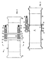
- reference numeral 10 designates an internal combustion engine (e.g. a diesel engine), and reference numeral 12 its exhaust system, the exhaust system comprising an exhaust manifold 14 and a series of silencer boxes 16.1, 16.2, and 16.3. Between the exhaust manifold 14 and the first silencer box 16.1 there is a knuckle joint 18. The knuckle joint 18 allows relative movement to take place between the exhaust manifold 14 and that part of the exhaust system downstream of the knuckle joint.
- the knuckle joint 18 comprises a first pipe segment 20 and a second pipe segment 22, the second pipe segment having an outwardly deformed end portion 24 which enters into a flared end portion 26 of the first pipe segment 20.
- the end portion 24 is deformed in such a manner that it has a convex outer surface and can enter with a small amount of clearance into the flared end portion 26.
- the pipe segment 20 has an end fitting 28 welded thereto and the pipe segment 22 an end fitting 30.
- the end fittings 28 and 30 enable the knuckle joint to be clamped into position in the exhaust system.
- the knuckle joint further comprises a flange 32 on the pipe segment 20 and a flange 34 on the pipe segment 22.
- the flange 32 is a sliding fit on the pipe segment 20, so that the flange can slide axially along the pipe segment and can also rotate with respect to the pipe segment about the axial direction.
- the flange 34 is likewise a sliding fit on the pipe segment 22.
- the knuckle joint further comprises three circumferentially spaced threaded bolts 36, each bolt passing through corresponding over-size holes in the flanges 32 and 34.
- Each bolt 36 has a cleave lock nut 40 thereon and a further coil spring 42 between the nut and the flange 32.
- end portion 24 has a convex outer surface enables the knuckle joint to flex. Furthermore, the fact that the flanges are a sliding fit on the pipe segments 20, 22 enables the pipe segments to swivel with respect to one another about their longitudinal axis.
- the knuckle joint on each exhaust manifold When used with an engine that has an exhaust manifold on each opposite side of the engine, the knuckle joint on each exhaust manifold may be mounted so as to extend in a vertical or near-vertical direction. In that event the one knuckle joint may be arranged to have characteristics that differ from those of the other knuckle joint. These characteristics may be such that, when the vehicle is at rest and the engine switched off, the parts of the knuckle joint on the left hand manifold are in the relative positions illustrated in Figure 5, whereas the parts of the knuckle joint on the right hand manifold are in the relative positions illustrated in Figure 6. It is to be noted that the curvature of the parts shown in Figures 5 and 6 has been exaggerated for purposes of illustration.
- the first portion 26 has a circumferentially extending, inwardly facing contact face 44 at or near the free end thereof, the second end portion 24 has a circumferentially extending, outwardly facing contact face 46, and there is an annular space 48 between the first and second end portions.
- the configuration of the first and second end portions is such that the pipe segments 20 and 22 are displaceable with respect to the one another in the axial direction, between a first extreme position in which the contact face 46 abuts on the inside surface of the first end portion (as shown in Figure 5), and a second extreme position in which the contact face 44 abuts on the outside surface of the second end portion 28 (as shown in Figure 6).
- a knuckle joint for use on the left hand exhaust manifold is provided with relatively short or weak coil springs 38.1 so that, in use, the contact face 46 normally abuts on the inside face of the first end portion 26 (as shown in Figure 5).
- a knuckle joint for use on the right hand exhaust manifold is provided with relatively long or strong coil springs 38.2 so that, in use, the contact face 44 normally abuts on the outside surface of the second end portion 28 (as shown in Figure 6).
- the following procedure is followed to obtain a deposit of soot on the surfaces defining the annular space 48.
- the vehicle's engine is started and allowed to idle for a short period of time and then switched off while the knuckle joint is still cold. During this short period some of the exhaust gases enter into the annular space 48, depositing soot on the surfaces defining the annular space of the knuckle joint on the right hand manifold. After the engine has been left to cool down, it is again started and, with the hand brake applied, the engine then torqued for a short period of time.
- the soot that collects on the surfaces defining the annular spaces 48 in this manner forms a deposit that acts as a lubricant between the opposed surfaces and also as a sealant against blowing through of exhaust gases.
Landscapes
- Engineering & Computer Science (AREA)
- General Engineering & Computer Science (AREA)
- Mechanical Engineering (AREA)
- Chemical & Material Sciences (AREA)
- Combustion & Propulsion (AREA)
- Exhaust Silencers (AREA)
- Clamps And Clips (AREA)
- Flanged Joints, Insulating Joints, And Other Joints (AREA)
- Joints Allowing Movement (AREA)
- Cylinder Crankcases Of Internal Combustion Engines (AREA)
- Gasket Seals (AREA)
- Earth Drilling (AREA)
Claims (6)
- Articulation à genouillère pour un système d'échappement, comprenant une première et une seconde section de tuyau (20, 22), la première section de tuyau (20) comportant une première extrémité (26) et la seconde section de tuyau comportant une seconde extrémité (24), qui entre dans la première extrémité de manière à mettre la première et la seconde section de tuyau en état de se déplacer l'un par rapport à l'autre, comportant une première bride (32) au premier segment de tuyau, une seconde bride au deuxième segment de tuyau, des moyens (36, 40, 42) pour rapprocher axialement la première bride et la seconde bride et, par conséquent, la première et la seconde section de tuyau, la seconde extrémité comprenant une seconde surface de contact (46), s'étendant à la périphérie, à ou près de son extrémité libre, ce qui a pour résultat que la seconde extrémité s'appuie contre la surface intérieure de la première extrémité (26) lorsque la première et la seconde section de tuyau se trouvent l'un envers l'autre par rapport à l'axe dans une première position finale, et comportant entre la première et la seconde bride un organe qui peut être comprimé de manière résiliente (38), ledit organe agissant sur les brides afin de les séparer de force par rapport à l'axe, caractérisée en ce que la première extrémité entre en contact avec la seconde extrémité sans joint d'étanchéité, constituant entre elles un espace annulaire (48) lorsque la première et la seconde section de tuyau se trouvent l'un par rapport à l'autre dans ladite première position finale, des gaz d'échappement pouvant entrer dans cet espace quand, lors du fonctionnement, ladite seconde surface de contact (46) se dégage de son contact avec la surface intérieure de la première extrémité afin de déposer de la suie sur les surfaces définissant l'espace annulaire, la suie ainsi déposée faisant l'office de lubrifiant entre les segments de tuyau et faisant l'office d'agent d'étanchéité contre les gaz d'échappement qui poussent par là.
- Articulation à genouillère selon la revendication 1, caractérisée en ce que l'organe qui peut être comprimé de manière résiliente est sous forme d'un ressort hélicoïdal (38).
- Articulation à genouillère selon la revendication 2, caractérisée en ce que le moyen comprend une pluralité de boulons (36) espacés l'un de l'autre à la périphérie, chaque boulon passant par une ouverture correspondante dans chacune des brides (32, 34) et en ce qu'un ressort hélicoïdal (38) mentionné ci-dessus est agencé sur chacun des boulons entre les brides.
- Articulation à genouillère selon une quelconque des revendications précédentes, caractérisée en ce qu'au moins une des brides (32, 34) est en ajustage glissant sur le segment de tuyau correspondant (20, 22).
- Articulation à genouillère selon une quelconque des revendications précédentes, caractérisée en ce que la première et la seconde section de tuyau (20, 22) sont axialement mobiles l'un par rapport à l'autre entre ladite première position finale et une deuxième position finale, la première section de tuyau (20) comprenant une première surface de contact (44) s'étendant à la circonférence à ou près de l'extrémité libre de la première extrémité (26), ce qui a pour résultat que la première extrémité bute contre la surface extérieure de la seconde extrémité (24) lorsque la première et la seconde section de tuyau se trouvent, l'un par rapport à l'autre, dans ladite deuxième position finale.
- Un système d'échappement pour un moteur à combustion interne comprenant une articulation à genouillère selon une quelconque des revendications précédentes.
Applications Claiming Priority (3)
| Application Number | Priority Date | Filing Date | Title |
|---|---|---|---|
| ZA9702002 | 1997-03-07 | ||
| ZA972002 | 1997-03-07 | ||
| PCT/GB1998/000694 WO1998039593A1 (fr) | 1997-03-07 | 1998-03-09 | Genouillere pour systeme d'echappement |
Publications (2)
| Publication Number | Publication Date |
|---|---|
| EP0965015A1 EP0965015A1 (fr) | 1999-12-22 |
| EP0965015B1 true EP0965015B1 (fr) | 2002-05-08 |
Family
ID=25586286
Family Applications (1)
| Application Number | Title | Priority Date | Filing Date |
|---|---|---|---|
| EP98910849A Expired - Lifetime EP0965015B1 (fr) | 1997-03-07 | 1998-03-09 | Genouillere pour systeme d'echappement |
Country Status (10)
| Country | Link |
|---|---|
| EP (1) | EP0965015B1 (fr) |
| AT (1) | ATE217402T1 (fr) |
| AU (1) | AU719546B2 (fr) |
| BR (1) | BR9808186A (fr) |
| CA (1) | CA2282829C (fr) |
| DE (1) | DE69805286T2 (fr) |
| DK (1) | DK0965015T3 (fr) |
| ES (1) | ES2178827T3 (fr) |
| NZ (1) | NZ338079A (fr) |
| WO (1) | WO1998039593A1 (fr) |
Families Citing this family (6)
| Publication number | Priority date | Publication date | Assignee | Title |
|---|---|---|---|---|
| DE19911814A1 (de) * | 1999-03-17 | 2000-09-21 | Bayerische Motoren Werke Ag | Flanschverbindung zwischen zwei Rohrstücken |
| GB2421063B (en) * | 2004-12-08 | 2009-09-02 | Terence Mckenna Thomson | Shock absorbing apparatus |
| DE102005010757A1 (de) | 2005-03-09 | 2006-09-21 | Audi Ag | Abgasanlage für ein Kraftfahrzeug |
| US20080277016A1 (en) * | 2007-05-09 | 2008-11-13 | Covers Robertus W | Exhaust tube interface for an exhaust treatment device |
| US9145994B2 (en) | 2011-05-04 | 2015-09-29 | Thomas & Belts International, LLC | Non-metallic expansion/deflection coupling modules |
| CN110027614B (zh) * | 2019-05-14 | 2023-11-21 | 江苏北人智能制造科技股份有限公司 | 转向节撑开装置、支柱总成与转向节的装配方法 |
Family Cites Families (4)
| Publication number | Priority date | Publication date | Assignee | Title |
|---|---|---|---|---|
| FR2449840A1 (fr) * | 1979-02-20 | 1980-09-19 | Renault | Jonction a rotule |
| FR2522726A1 (fr) * | 1982-03-04 | 1983-09-09 | Renault | Jonction a rotule, notamment pour tuyau d'echappement |
| FR2647504B1 (fr) * | 1989-05-26 | 1991-08-30 | Dubois Jacques | Accouplement d'echappement flexible |
| DE19508979C2 (de) * | 1994-05-20 | 2000-08-10 | Daimler Chrysler Ag | Flanschverbindung zweier Rohrabschnitte im Abgasleitungssystem einer Brennkraftmaschine |
-
1998
- 1998-03-09 AT AT98910849T patent/ATE217402T1/de not_active IP Right Cessation
- 1998-03-09 WO PCT/GB1998/000694 patent/WO1998039593A1/fr not_active Ceased
- 1998-03-09 ES ES98910849T patent/ES2178827T3/es not_active Expired - Lifetime
- 1998-03-09 NZ NZ338079A patent/NZ338079A/xx unknown
- 1998-03-09 CA CA002282829A patent/CA2282829C/fr not_active Expired - Fee Related
- 1998-03-09 DK DK98910849T patent/DK0965015T3/da active
- 1998-03-09 EP EP98910849A patent/EP0965015B1/fr not_active Expired - Lifetime
- 1998-03-09 BR BR9808186-1A patent/BR9808186A/pt not_active IP Right Cessation
- 1998-03-09 DE DE69805286T patent/DE69805286T2/de not_active Expired - Lifetime
- 1998-03-09 AU AU65078/98A patent/AU719546B2/en not_active Ceased
Also Published As
| Publication number | Publication date |
|---|---|
| WO1998039593A1 (fr) | 1998-09-11 |
| BR9808186A (pt) | 2000-05-16 |
| ES2178827T3 (es) | 2003-01-01 |
| DE69805286D1 (de) | 2002-06-13 |
| DE69805286T2 (de) | 2003-01-02 |
| EP0965015A1 (fr) | 1999-12-22 |
| AU719546B2 (en) | 2000-05-11 |
| ATE217402T1 (de) | 2002-05-15 |
| NZ338079A (en) | 2000-10-27 |
| AU6507898A (en) | 1998-09-22 |
| DK0965015T3 (da) | 2002-09-02 |
| CA2282829A1 (fr) | 1998-09-11 |
| CA2282829C (fr) | 2008-06-10 |
Similar Documents
| Publication | Publication Date | Title |
|---|---|---|
| US6164067A (en) | Knuckle joint for an exhaust system | |
| CA1143409A (fr) | Raccord pour elements tubulaires | |
| EP0183799B1 (fr) | Joint flexible pour tuyaux | |
| EP1045185A2 (fr) | Raccord de tuyaux | |
| EP2405172B1 (fr) | Couplage de tuyaux | |
| US20050258642A1 (en) | Exhaust pipe joint and seal | |
| US4893847A (en) | Bearing seal for universal ball joint | |
| US5944363A (en) | Flexible connector systems | |
| US6109661A (en) | Flexible coupler apparatus | |
| EP1705347B1 (fr) | Manchon à soufflets pour le contrôle dynamique de la torsion dans un système d'échappement | |
| US4475623A (en) | Universal muffler assembly | |
| US4597596A (en) | Cylinder end seal | |
| US6042154A (en) | Arrangement for joining tubular duct sections | |
| US4730852A (en) | Vehicle exhaust repair device | |
| AU719546B2 (en) | Knuckle joint for an exhaust system | |
| US6193280B1 (en) | Exhaust connector assembly and kit for a segmented exhaust manifold | |
| GB1586244A (en) | Engine exhaust system in a vehicle | |
| WO2024158492A1 (fr) | Couvercle pour joint de cardan d'un arbre d'entraînement | |
| US5924282A (en) | Vehicle with improved exhaust system for internal combustion engine | |
| US6053212A (en) | Length-controlled flexible hose and method of manufacturing same | |
| JPH08200059A (ja) | 排気マニホルドジョイント | |
| CA2065680A1 (fr) | Joint de bride a fil de cisaillement | |
| JPH06249343A (ja) | 熱で誘起する移動を制御するガスケット組立体 | |
| GB2256688A (en) | Universal and telescopic pipe joint | |
| RU2175093C1 (ru) | Соединительный узел трубопровода |
Legal Events
| Date | Code | Title | Description |
|---|---|---|---|
| PUAI | Public reference made under article 153(3) epc to a published international application that has entered the european phase |
Free format text: ORIGINAL CODE: 0009012 |
|
| 17P | Request for examination filed |
Effective date: 19990830 |
|
| AK | Designated contracting states |
Kind code of ref document: A1 Designated state(s): AT BE CH DE DK ES FI FR GB GR IE IT LI NL PT SE |
|
| 17Q | First examination report despatched |
Effective date: 20001103 |
|
| GRAG | Despatch of communication of intention to grant |
Free format text: ORIGINAL CODE: EPIDOS AGRA |
|
| GRAG | Despatch of communication of intention to grant |
Free format text: ORIGINAL CODE: EPIDOS AGRA |
|
| GRAH | Despatch of communication of intention to grant a patent |
Free format text: ORIGINAL CODE: EPIDOS IGRA |
|
| GRAH | Despatch of communication of intention to grant a patent |
Free format text: ORIGINAL CODE: EPIDOS IGRA |
|
| REG | Reference to a national code |
Ref country code: GB Ref legal event code: IF02 |
|
| GRAA | (expected) grant |
Free format text: ORIGINAL CODE: 0009210 |
|
| AK | Designated contracting states |
Kind code of ref document: B1 Designated state(s): AT BE CH DE DK ES FI FR GB GR IE IT LI NL PT SE |
|
| PG25 | Lapsed in a contracting state [announced via postgrant information from national office to epo] |
Ref country code: GR Free format text: LAPSE BECAUSE OF FAILURE TO SUBMIT A TRANSLATION OF THE DESCRIPTION OR TO PAY THE FEE WITHIN THE PRESCRIBED TIME-LIMIT Effective date: 20020508 |
|
| REF | Corresponds to: |
Ref document number: 217402 Country of ref document: AT Date of ref document: 20020515 Kind code of ref document: T |
|
| REG | Reference to a national code |
Ref country code: CH Ref legal event code: EP |
|
| REG | Reference to a national code |
Ref country code: IE Ref legal event code: FG4D |
|
| REF | Corresponds to: |
Ref document number: 69805286 Country of ref document: DE Date of ref document: 20020613 |
|
| PG25 | Lapsed in a contracting state [announced via postgrant information from national office to epo] |
Ref country code: PT Free format text: LAPSE BECAUSE OF FAILURE TO SUBMIT A TRANSLATION OF THE DESCRIPTION OR TO PAY THE FEE WITHIN THE PRESCRIBED TIME-LIMIT Effective date: 20020808 |
|
| REG | Reference to a national code |
Ref country code: DK Ref legal event code: T3 |
|
| ET | Fr: translation filed | ||
| REG | Reference to a national code |
Ref country code: ES Ref legal event code: FG2A Ref document number: 2178827 Country of ref document: ES Kind code of ref document: T3 |
|
| PG25 | Lapsed in a contracting state [announced via postgrant information from national office to epo] |
Ref country code: IE Free format text: LAPSE BECAUSE OF NON-PAYMENT OF DUE FEES Effective date: 20030310 |
|
| PLBE | No opposition filed within time limit |
Free format text: ORIGINAL CODE: 0009261 |
|
| STAA | Information on the status of an ep patent application or granted ep patent |
Free format text: STATUS: NO OPPOSITION FILED WITHIN TIME LIMIT |
|
| BECA | Be: change of holder's address |
Owner name: 52 CORLETT DRIVE, ILLOVO, JOHANNESBURG (ZA) Effective date: 20030423 Owner name: THE *ARGIL - IDC VENTURE CAPITAL TRUST FIND101 ST Effective date: 20030423 Owner name: THE *VIBOL TRUST Effective date: 20030423 |
|
| BECH | Be: change of holder |
Owner name: THE *ARGIL - IDC VENTURE CAPITAL TRUST FIND Effective date: 20030423 Owner name: THE *VIBOL TRUST Effective date: 20030423 |
|
| 26N | No opposition filed |
Effective date: 20030211 |
|
| REG | Reference to a national code |
Ref country code: CH Ref legal event code: PUEA Owner name: THE ARGIL-IDC VENTURE CAPITAL TRUST FUND Free format text: CRONJE, JACOBUS#2 FUCHSIA CLOSE, PLATTEKLOOF EXTENSION 11#PAROW 7500 (ZA) -TRANSFER TO- THE ARGIL-IDC VENTURE CAPITAL TRUST FUND#52 CORLETT DRIVE ILLOWO#JOHANNESBURG, 2196 (ZA) $ THE VIBOL TRUST#101 ST. GEORGES MALL#CAPE TOWN, 8000 (ZA) Ref country code: CH Ref legal event code: NV Representative=s name: HANS RUDOLF GACHNANG PATENTANWALT |
|
| NLS | Nl: assignments of ep-patents |
Owner name: THE VIBOL TRUST Owner name: THE ARGILL - IDC VENTURE CAPITAL TRUST FUND |
|
| REG | Reference to a national code |
Ref country code: GB Ref legal event code: 732E |
|
| REG | Reference to a national code |
Ref country code: FR Ref legal event code: TQ Ref country code: FR Ref legal event code: TP |
|
| REG | Reference to a national code |
Ref country code: IE Ref legal event code: MM4A |
|
| REG | Reference to a national code |
Ref country code: ES Ref legal event code: PC2A |
|
| PGFP | Annual fee paid to national office [announced via postgrant information from national office to epo] |
Ref country code: ES Payment date: 20090327 Year of fee payment: 12 Ref country code: DK Payment date: 20090313 Year of fee payment: 12 Ref country code: AT Payment date: 20090317 Year of fee payment: 12 |
|
| PGFP | Annual fee paid to national office [announced via postgrant information from national office to epo] |
Ref country code: NL Payment date: 20090317 Year of fee payment: 12 Ref country code: FI Payment date: 20090313 Year of fee payment: 12 |
|
| PGFP | Annual fee paid to national office [announced via postgrant information from national office to epo] |
Ref country code: CH Payment date: 20090316 Year of fee payment: 12 |
|
| PGFP | Annual fee paid to national office [announced via postgrant information from national office to epo] |
Ref country code: SE Payment date: 20090312 Year of fee payment: 12 Ref country code: IT Payment date: 20090324 Year of fee payment: 12 |
|
| PGFP | Annual fee paid to national office [announced via postgrant information from national office to epo] |
Ref country code: BE Payment date: 20090430 Year of fee payment: 12 |
|
| BERE | Be: lapsed |
Owner name: THE *ARGIL - IDC VENTURE CAPITAL TRUST FIND Effective date: 20100331 Owner name: THE *VIBOL TRUST Effective date: 20100331 |
|
| REG | Reference to a national code |
Ref country code: NL Ref legal event code: V1 Effective date: 20101001 |
|
| REG | Reference to a national code |
Ref country code: CH Ref legal event code: PL |
|
| EUG | Se: european patent has lapsed | ||
| REG | Reference to a national code |
Ref country code: DK Ref legal event code: EBP |
|
| PG25 | Lapsed in a contracting state [announced via postgrant information from national office to epo] |
Ref country code: FI Free format text: LAPSE BECAUSE OF NON-PAYMENT OF DUE FEES Effective date: 20100309 Ref country code: AT Free format text: LAPSE BECAUSE OF NON-PAYMENT OF DUE FEES Effective date: 20100309 |
|
| PG25 | Lapsed in a contracting state [announced via postgrant information from national office to epo] |
Ref country code: NL Free format text: LAPSE BECAUSE OF NON-PAYMENT OF DUE FEES Effective date: 20101001 |
|
| PG25 | Lapsed in a contracting state [announced via postgrant information from national office to epo] |
Ref country code: LI Free format text: LAPSE BECAUSE OF NON-PAYMENT OF DUE FEES Effective date: 20100331 Ref country code: CH Free format text: LAPSE BECAUSE OF NON-PAYMENT OF DUE FEES Effective date: 20100331 Ref country code: BE Free format text: LAPSE BECAUSE OF NON-PAYMENT OF DUE FEES Effective date: 20100331 |
|
| PG25 | Lapsed in a contracting state [announced via postgrant information from national office to epo] |
Ref country code: IT Free format text: LAPSE BECAUSE OF NON-PAYMENT OF DUE FEES Effective date: 20100309 |
|
| REG | Reference to a national code |
Ref country code: ES Ref legal event code: FD2A Effective date: 20110419 |
|
| PG25 | Lapsed in a contracting state [announced via postgrant information from national office to epo] |
Ref country code: DK Free format text: LAPSE BECAUSE OF NON-PAYMENT OF DUE FEES Effective date: 20100331 |
|
| PG25 | Lapsed in a contracting state [announced via postgrant information from national office to epo] |
Ref country code: ES Free format text: LAPSE BECAUSE OF NON-PAYMENT OF DUE FEES Effective date: 20110404 |
|
| PG25 | Lapsed in a contracting state [announced via postgrant information from national office to epo] |
Ref country code: ES Free format text: LAPSE BECAUSE OF NON-PAYMENT OF DUE FEES Effective date: 20100310 |
|
| PG25 | Lapsed in a contracting state [announced via postgrant information from national office to epo] |
Ref country code: SE Free format text: LAPSE BECAUSE OF NON-PAYMENT OF DUE FEES Effective date: 20100310 |
|
| PGFP | Annual fee paid to national office [announced via postgrant information from national office to epo] |
Ref country code: FR Payment date: 20121002 Year of fee payment: 15 |
|
| PGFP | Annual fee paid to national office [announced via postgrant information from national office to epo] |
Ref country code: DE Payment date: 20130930 Year of fee payment: 16 |
|
| PGFP | Annual fee paid to national office [announced via postgrant information from national office to epo] |
Ref country code: GB Payment date: 20130930 Year of fee payment: 16 |
|
| REG | Reference to a national code |
Ref country code: FR Ref legal event code: ST Effective date: 20131129 |
|
| PG25 | Lapsed in a contracting state [announced via postgrant information from national office to epo] |
Ref country code: FR Free format text: LAPSE BECAUSE OF NON-PAYMENT OF DUE FEES Effective date: 20130402 |
|
| REG | Reference to a national code |
Ref country code: DE Ref legal event code: R119 Ref document number: 69805286 Country of ref document: DE |
|
| GBPC | Gb: european patent ceased through non-payment of renewal fee |
Effective date: 20140309 |
|
| REG | Reference to a national code |
Ref country code: DE Ref legal event code: R119 Ref document number: 69805286 Country of ref document: DE Effective date: 20141001 |
|
| PG25 | Lapsed in a contracting state [announced via postgrant information from national office to epo] |
Ref country code: GB Free format text: LAPSE BECAUSE OF NON-PAYMENT OF DUE FEES Effective date: 20140309 Ref country code: DE Free format text: LAPSE BECAUSE OF NON-PAYMENT OF DUE FEES Effective date: 20141001 |