EP0965417A2 - Robot controlling system - Google Patents
Robot controlling system Download PDFInfo
- Publication number
- EP0965417A2 EP0965417A2 EP99304840A EP99304840A EP0965417A2 EP 0965417 A2 EP0965417 A2 EP 0965417A2 EP 99304840 A EP99304840 A EP 99304840A EP 99304840 A EP99304840 A EP 99304840A EP 0965417 A2 EP0965417 A2 EP 0965417A2
- Authority
- EP
- European Patent Office
- Prior art keywords
- unit
- robot
- controlling
- servo amplifier
- amplifier unit
- Prior art date
- Legal status (The legal status is an assumption and is not a legal conclusion. Google has not performed a legal analysis and makes no representation as to the accuracy of the status listed.)
- Granted
Links
Images


Classifications
-
- B—PERFORMING OPERATIONS; TRANSPORTING
- B25—HAND TOOLS; PORTABLE POWER-DRIVEN TOOLS; MANIPULATORS
- B25J—MANIPULATORS; CHAMBERS PROVIDED WITH MANIPULATION DEVICES
- B25J9/00—Program-controlled manipulators
- B25J9/16—Program controls
- B25J9/1602—Program controls characterised by the control system, structure, architecture
-
- G—PHYSICS
- G05—CONTROLLING; REGULATING
- G05B—CONTROL OR REGULATING SYSTEMS IN GENERAL; FUNCTIONAL ELEMENTS OF SUCH SYSTEMS; MONITORING OR TESTING ARRANGEMENTS FOR SUCH SYSTEMS OR ELEMENTS
- G05B19/00—Program-control systems
- G05B19/02—Program-control systems electric
- G05B19/18—Numerical control [NC], i.e. automatically operating machines, in particular machine tools, e.g. in a manufacturing environment, so as to execute positioning, movement or co-ordinated operations by means of program data in numerical form
- G05B19/414—Structure of the control system, e.g. common controller or multiprocessor systems, interface to servo, programmable interface controller
- G05B19/4144—Structure of the control system, e.g. common controller or multiprocessor systems, interface to servo, programmable interface controller characterised by using multiplexing for control system
Definitions
- the present invention relates to a system to control an industrial robot (hereinafter referred to simply as a "robot”).
- a robot normally comprises a robot arm into which a servomotor has been incorporated, and the said servomotor is driven by a servo-amplifier unit.
- the control of the robot is performed by giving commands to the servo-amplifier unit by a controlling device.
- FIG. 5 is a schematic block diagram to explain the conventional robot control.
- a robot in a form shown in Japanese Patent Application Laid-Open No. 8-11074 specification for example is shown as an example of the conventional robot.
- a controlling unit 1 controls a servo amplifier unit 2, and, based on the control, the servo amplifier unit 2 supplies a power to a servomotor 31 of a robot unit 3.
- the servomotor 31 is incorporated into every robot arm 32, and controlled by the controlling unit 1 via the servo amplifier unit 2.
- the controlling unit 1 sends a PWM command to the servo amplifier unit 2 and obtains a current feedback value from the servo amplifier unit 2.
- the controlling unit 1 outputs an output for an end effector to the robot 3 and inputs a servomotor speed feedback signal, a servomotor position feedback signal, an end effector input signal, and a robot overtravel signal from the robot 3.
- the controlling unit 1 conducts current control of a servo motor system based on the current feedback value, and speed control or position control of the servomotor system based on the servomotor speed feedback signals or the servomotor position feedback signals. In addition, by input and output signals for the end effector, control of every kind of function which the robot comprises is conducted and by a robot overtravel signal an over movement of the robot arm is detected.
- Japanese Patent Application Laid-Open No. 8-229862 discloses placing a servo amplifier in the vicinity of a motor mounted on a body of the robot for the purpose of making wiring of power cables shorter.
- An object of the present invention is to solve the conventional problems and decrease the number of wirings, kinds of cable lengths and their quantity in the robot controlling system.
- the robot controlling system of the present invention is configured to comprise a robot unit including a robot arm and a servomotor, a servo amplifier unit to drive the servomotor, and a controlling unit to control the robot arm by sending commands to the servo amplifier unit, and transmission and reception means between the controlling unit and the robot unit is conducted via the servo amplifier unit with transmit-receive means between the controlling unit and the robot unit being incorporated into transmit-receive means between the controlling unit and the servo amplifier unit and into transmit-receive means between the servo amplifier unit and the robot unit in the robot controlling system.
- a command to be sent from the control unit to the robot unit as well as communication on feedback signals and detection signals to be sent from the robot unit to the controlling unit are conducted in use of transmit-receive means between the controlling unit and the servo amplifier unit as well as transmit-receive means between the servo amplifier unit and the robot unit via the servo amplifier unit.
- This configuration serves to make it possible to omit transmit-receive means such as conventionally required cables, etc. to attain connection between the controlling unit and the robot unit, and thus to decrease the number of cables.
- the transmit-receive means between the controlling unit and the servo amplifier unit may be configured to comprise communication means, and for the transmission and reception between the controlling unit and the robot unit, the transmission and reception between the controlling unit and the servo amplifier unit is conducted through the communication means.
- FIG. 1 is a block diagram showing a configuration example of the servo controlling system of the present invention.
- the controlling unit 1 controls the servo amplifier unit 2, and the servo amplifier unit 2 supplies a power to the servomotor 31 of the robot unit 3 based on the controL
- the servo motor 31 is incorporated into every robot arm 32, and controlled by the controlling unit 1 via the servo amplifier unit 2.
- the controlling unit 1 sends a PWM command to the servo amplifier unit 2.
- the servo amplifier unit 2 supplies a drive current to the servo motor 31 of the robot unit 3 via an power line for the servo motor based on the said PWM command.
- the servo amplifier unit 2 feeds back a current feedback value to the control unit 1, and feeds back to the controlling unit 1 a speed feedback signal or a position feedback signal of the servo motor which are received from the servo motor 31.
- controlling unit 1 sends to the robot unit 3 via the servo amplifier unit an output signal for an end effector to operate end effectors such as hands of the robot unit 3, etc.
- robot unit 3 sends to the controlling unit 1 via the servo amplifier unit 2 an input signal for the end effector to notify the performance status of the end effector as well as a robot overtravel signal to notify the over movement of a robot arm.
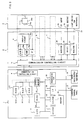
- FIG. 2 is a block diagram in the case where communication connection is provided between the controlling unit 1 and the servo amplifier unit 2.
- the configuration of the controlling unit 1, the servo amplifier unit 2, and the robot unit 3 as well as connection between the servo amplifier unit 2 and the robot unit 3 constitute a configuration similar to that shown in FIG. 1 but dissimilar to that shown in FIG. 1 on the point that the connection between the controlling unit 1 and the servo amplifier unit 2 is implemented by way of communication.
- controlling unit 1 as well as the servo amplifier unit 2 respectively comprise the transmit-receive controlling circuits, and the control of bidirectional communication is implemented in accordance with a predetermined communication protocoL
- the bidirectional communication can be configured to use lines respectively assigned for the forward way and the return way and also can be configured to share the same line for the forward way and the return way.
- cables between the controlling unit 1 and the robot unit 3 can be omitted, and in the case where the communication between the controlling unit 1 and the servo amplifier unit 2 is conducted by serial transmission, the number of cables to be disposed can be decreased into one, resulting in implementation of further decrease in the quantity of cables.
- the control unit 1 has a central processing unit (CPU)11, and to the CPU 11 memories such as ROM 12, DRAM 13, and SRAM 14, etc. are connected via buses.
- SRAM 14 configures a nonvolatile memory with backup of a battery 15.
- an instruction operation panel 17 is connected via an interface 16
- an outside input/output equipment 19 is connected via communication port 18 (or a general-purpose interface).
- Display means such as a liquid crystal display, etc. can be provided in the teaching control panel 17.
- the outer input/output equipment 19 those such as a hand, a conveyer, a work box switching equipment, a spot gun, an alarm lamp, a buzzer, and an off-line programming equipment, etc. can be used.
- ROM 12 various programs are stored so that CPU 11 may conduct control of the robot unit 3 and the controlling unit 1 itself.
- the DRAM 13 is a memory to be used for temporal memorization as well as operation of data.
- various parameter set points as well as program data are stored by manual input from the teaching control panel 17 or off-line input to be conducted via the communication port 18 or a general-purpose interface.
- a robot pivot controlling unit 10 is connected via a shared memory 20.
- a digital signal processor (DSP) 10-1 is a processor to solely control a robot axis
- the ROM 10-2 is a memory to store a program to conduct control of the robot axis
- the RAM 10-3 is a memory solely for the DSP to store the processed data and set parameters attained by the DSP 10-1.
- the communication controlling circuit 4 exchanges signal transmission with the transmission controlling circuit 5 at the party of the servo amplifier unit 2. From the party of controlling unit 1 to the party of servo amplifier unit 2, command signals for the PWM and the like for axis control which have been processed in the robot axis controlling unit 10, and signals such as of an output for an end effector, etc. are sent:
- the servo amplifier unit 2 comprises a communication controlling circuit 5, parts 21a, 22a, 23a, and 24a which conduct control of power supply to the servomotor 31a of the robot unit 3, receivers 25 and 27, and a driver 26.
- the robot unit 3 comprises a servomotor 31a incorporated in each robot arm, detector 33a to detect the rotation status such as speed and position, etc. of the servomotor 31a, an end effector input terminal 35 related to end effector such as hand, and an end effector output terminal 36, and a limit switch 37 for over travel and the like.
- the communication controlling circuit 5 of the servo amplifier unit 2 is a unit to exchange signal transmission with the controlling unit 1, and receives from the controlling unit 1 signals such as PWM command signals, and signals for output for the end effector, or the like, and sends to the control unit 1 signals such as current feedback signals, servomotor's speed/position feedback signals, and signals for input for the end effector, and robot overtravel, etc.
- the PWM controlling unit 23a controls currents in an inverter circuit 21a based on a PWM command to form the driving current, and the inverter circuit 21a supplies the drive currents to the servomotor 31a.
- an A/D conversion circuit 22a digitally converts the current feedback values of currents to be supplied to the servomotor 31a, and thereafter to be sent to the transmission controlling circuit 5.
- speed feedback signals or position feedback signals are sent to the communication controlling circuit 5 via the interface 24a.
- FIG. 3 shows a portion, which controls power supply to these other servomotors based on signals having been transmitted from the controlling unit 1, being enclosed by dotted lines “b” and “c.” Accordingly, as shown by dotted lines “a,” “b,” and “c” in FIG. 3, power supply is controlled for each servomotor.
- the communication controlling circuit 5 of the servo amplifier unit 2 transmits to the controlling unit 1 via the communication controlling circuit 4 of the controlling unit 1 feedback values of currents to be supplied to each servomotor 31a, and the outputs speed feedback signals or position feedback signals from position or speed detectors 33a attached to each servomotor.
- the receiver 25 receives signals from the end effector input terminal 35 of the robot unit 3 to send them to the communication controlling circuit 5, while the receiver 27 receives signals from the limit switch 37 for overtravels of the robot unit 3 to send them to the communication controlling circuit 5.
- the driver 26 sends an output for the end effector from the communication controlling circuit 5 toward the end effector output terminal 36 of the robot unit 3.
- the communication controlling circuit 5 of the servo amplifier unit 2 acts as a repeater of speed feedback signals or position feedback signals, and each of input signals for end effector as well as overtravel signals from the robot unit 3 to the controlling unit 1, and acts as a repeater of output signals for end effector from the controlling unit 1 to the robot unit 3, and thus wiring and cables between the controlling unit 1 and the robot unit 3 can be omitted.
- FIG. 4 is a block diagram explaining an example of configuration of a communication controlling circuits 4 and 5 and shows the case of bidirectional communication which is configured to use respective lines for the forward way and the return way,
- transmission is configured by the transmission controlling circuit 41 and the P/S (parallel/serial) conversion circuit 42, and serial signals are transmitted to the communication controlling circuit 5.
- reception is configured by the S/P (serial/parallel) conversion circuit 44 and the reception control circuit 43, and signal processing is conducted in a signal form of parallel signals.
- transmission is configured by the transmission controlling circuit 51 and the P/S (parallel/serial) conversion circuit 52, and serial signals are transmitted to the communication controlling circuit 4.
- reception is configured by the S/P (serial /parallel) conversion circuit 54 and the reception control circuit 53, and signal processing is conducted in a signal form of parallel signals.
- the decrease in terms of quantity of wiring, kinds of length of cables and number of cables can be attained.
Landscapes
- Engineering & Computer Science (AREA)
- Automation & Control Theory (AREA)
- Robotics (AREA)
- Mechanical Engineering (AREA)
- Human Computer Interaction (AREA)
- Manufacturing & Machinery (AREA)
- Physics & Mathematics (AREA)
- General Physics & Mathematics (AREA)
- Manipulator (AREA)
- Numerical Control (AREA)
Abstract
Description
Claims (3)
- A robot controlling system, comprising a robot unit including a robot arm and a servomotor, a servo amplifier unit to drive said servomotor; and a controlling unit to control said robot arm by sending commands to said servo amplifier unit, wherein transmission and reception between said controlling unit and said robot unit is conducted via said servo amplifier unit with transmit-receive means between said controlling unit and said robot unit being incorporated into transmit-receive means between said controlling unit and said servo amplifier unit as well as into transmit-receive means between said servo amplifier unit and said robot unit in said robot controlling system.
- The robot control system according to claim 1, wherein said transmit-receive means between said controlling unit and said servo amplifier unit comprises communication means.
- A robot controlling system, comprising:a robot unit including a robot and servomotors to drive each axis of said robot,a servo amplifier unit to control power supply to said respective servomotors, anda controlling unit to send commands for controlling said robot to said servo amplifier unit,wherein both of said servo amplifier unit and said controlling unit comprise communication controlling circuits respectively, and connection to and from both of said communication controlling circuit is implemented with communication lines, andsaid servo amplifier unit comprises an interface to receive output signals from a position or speed detector connected to said servomotors and send them to a communication controlling circuit of said servo amplifier unit, a receiver to receive outputs from an end effector of said robot and send them to a communication controlling circuit of said servo amplifier unit, a driver to receive signals for said end effector from said communication controlling circuit and send them to the end effector of said robot.
Applications Claiming Priority (2)
| Application Number | Priority Date | Filing Date | Title |
|---|---|---|---|
| JP10189873A JP2000006070A (en) | 1998-06-19 | 1998-06-19 | Robot control system |
| JP18987398 | 1998-06-19 |
Publications (3)
| Publication Number | Publication Date |
|---|---|
| EP0965417A2 true EP0965417A2 (en) | 1999-12-22 |
| EP0965417A3 EP0965417A3 (en) | 2001-11-07 |
| EP0965417B1 EP0965417B1 (en) | 2006-10-11 |
Family
ID=16248613
Family Applications (1)
| Application Number | Title | Priority Date | Filing Date |
|---|---|---|---|
| EP99304840A Expired - Lifetime EP0965417B1 (en) | 1998-06-19 | 1999-06-21 | Robot controlling system |
Country Status (4)
| Country | Link |
|---|---|
| US (1) | US6181096B1 (en) |
| EP (1) | EP0965417B1 (en) |
| JP (1) | JP2000006070A (en) |
| DE (1) | DE69933509T2 (en) |
Cited By (4)
| Publication number | Priority date | Publication date | Assignee | Title |
|---|---|---|---|---|
| WO2005036289A1 (en) * | 2003-09-02 | 2005-04-21 | National Instruments Corporation | Re-configurable motion controller drive |
| CN102915034A (en) * | 2012-10-10 | 2013-02-06 | 河南省电力公司洛阳供电公司 | Control system of small wheeled robot applied to cable tunnels |
| CN105291105A (en) * | 2015-12-09 | 2016-02-03 | 哈尔滨云控机器人科技有限公司 | Mechanical arm remote control method based on mobile terminals |
| CN105472378A (en) * | 2015-12-09 | 2016-04-06 | 哈尔滨云控机器人科技有限公司 | Product quality test method based on low-cost cameras |
Families Citing this family (12)
| Publication number | Priority date | Publication date | Assignee | Title |
|---|---|---|---|---|
| DE10030358A1 (en) * | 2000-06-21 | 2002-01-03 | Heidenhain Gmbh Dr Johannes | Method and device for serial data transmission between a position measuring system and a processing unit |
| US8000837B2 (en) * | 2004-10-05 | 2011-08-16 | J&L Group International, Llc | Programmable load forming system, components thereof, and methods of use |
| JP4805629B2 (en) | 2005-08-04 | 2011-11-02 | 本田技研工業株式会社 | Encoder |
| US9119655B2 (en) | 2012-08-03 | 2015-09-01 | Stryker Corporation | Surgical manipulator capable of controlling a surgical instrument in multiple modes |
| US9921712B2 (en) | 2010-12-29 | 2018-03-20 | Mako Surgical Corp. | System and method for providing substantially stable control of a surgical tool |
| US9226796B2 (en) | 2012-08-03 | 2016-01-05 | Stryker Corporation | Method for detecting a disturbance as an energy applicator of a surgical instrument traverses a cutting path |
| CN119097419A (en) | 2012-08-03 | 2024-12-10 | 史赛克公司 | Systems and methods for robotic surgery |
| US9820818B2 (en) | 2012-08-03 | 2017-11-21 | Stryker Corporation | System and method for controlling a surgical manipulator based on implant parameters |
| CN106073896A (en) * | 2016-06-15 | 2016-11-09 | 重庆金山科技(集团)有限公司 | A kind of motor for operating robot controls network and method |
| EP3554414A1 (en) | 2016-12-16 | 2019-10-23 | MAKO Surgical Corp. | Techniques for modifying tool operation in a surgical robotic system based on comparing actual and commanded states of the tool relative to a surgical site |
| DE112019007060B4 (en) * | 2019-04-19 | 2023-03-16 | Mitsubishi Electric Corporation | robot |
| US11264929B2 (en) * | 2019-09-18 | 2022-03-01 | Rockwell Automation Technologies, Inc. | Systems and methods for non-rigid load vibration control |
Family Cites Families (9)
| Publication number | Priority date | Publication date | Assignee | Title |
|---|---|---|---|---|
| JPS62280907A (en) * | 1986-05-29 | 1987-12-05 | Fanuc Ltd | Positioning system |
| JP2673543B2 (en) * | 1988-06-01 | 1997-11-05 | ファナック株式会社 | Excessive Error Detection Method in Servo Motor Control |
| JPH03118618A (en) * | 1989-09-30 | 1991-05-21 | Fanuc Ltd | Control system applying sliding mode control having damping effect |
| JP2954615B2 (en) * | 1989-11-24 | 1999-09-27 | 株式会社日立製作所 | Motor drive control device |
| GB2256290B (en) * | 1991-05-27 | 1994-07-20 | Honda Motor Co Ltd | Servomotor control system for multi-axes |
| JP2732159B2 (en) * | 1991-10-29 | 1998-03-25 | ファナック株式会社 | Abnormal load detection method |
| US5349277A (en) * | 1992-03-12 | 1994-09-20 | Honda Giken Kogyo Kabushiki Kaisha | Control system for legged mobile robot |
| JP2574983B2 (en) * | 1993-04-06 | 1997-01-22 | 本田技研工業株式会社 | Multitask control system |
| GB2315135B (en) * | 1996-07-10 | 2000-12-06 | Honda Motor Co Ltd | Control apparatus for welding robot |
-
1998
- 1998-06-19 JP JP10189873A patent/JP2000006070A/en active Pending
-
1999
- 1999-06-21 EP EP99304840A patent/EP0965417B1/en not_active Expired - Lifetime
- 1999-06-21 US US09/336,705 patent/US6181096B1/en not_active Expired - Fee Related
- 1999-06-21 DE DE69933509T patent/DE69933509T2/en not_active Expired - Fee Related
Cited By (7)
| Publication number | Priority date | Publication date | Assignee | Title |
|---|---|---|---|---|
| WO2005036289A1 (en) * | 2003-09-02 | 2005-04-21 | National Instruments Corporation | Re-configurable motion controller drive |
| US7103424B2 (en) | 2003-09-02 | 2006-09-05 | National Instruments Corporation | Re-configurable motion controller drive |
| CN102915034A (en) * | 2012-10-10 | 2013-02-06 | 河南省电力公司洛阳供电公司 | Control system of small wheeled robot applied to cable tunnels |
| CN105291105A (en) * | 2015-12-09 | 2016-02-03 | 哈尔滨云控机器人科技有限公司 | Mechanical arm remote control method based on mobile terminals |
| CN105472378A (en) * | 2015-12-09 | 2016-04-06 | 哈尔滨云控机器人科技有限公司 | Product quality test method based on low-cost cameras |
| CN105291105B (en) * | 2015-12-09 | 2017-08-11 | 哈尔滨云控机器人科技有限公司 | Mechanical arm long-range control method based on mobile terminal |
| CN105472378B (en) * | 2015-12-09 | 2017-08-29 | 哈尔滨云控机器人科技有限公司 | A kind of product quality detection method based on inexpensive camera |
Also Published As
| Publication number | Publication date |
|---|---|
| JP2000006070A (en) | 2000-01-11 |
| DE69933509T2 (en) | 2007-02-01 |
| DE69933509D1 (en) | 2006-11-23 |
| EP0965417B1 (en) | 2006-10-11 |
| EP0965417A3 (en) | 2001-11-07 |
| US6181096B1 (en) | 2001-01-30 |
Similar Documents
| Publication | Publication Date | Title |
|---|---|---|
| EP0965417B1 (en) | Robot controlling system | |
| US5749058A (en) | Robot safety system for connecting peripheral device to a robot controller | |
| JPH11299291A (en) | Multi-axis motor controller | |
| US6914790B2 (en) | Motor driving controller | |
| US6396030B1 (en) | Robot control device | |
| CA2528564A1 (en) | Vehicle integrated radio remote control | |
| KR20140062848A (en) | Control system of portable welding robot | |
| US5994861A (en) | Servo system | |
| JP3645668B2 (en) | Motor control device | |
| EP0451825B1 (en) | Multi-transmission method and multi-transmission system for a vehicle | |
| US5621292A (en) | Servo amplifier and servo system which reduce cable interface | |
| DE112019007060B4 (en) | robot | |
| JPH0724765A (en) | Correction data communication system among robots | |
| EP0919894B1 (en) | Controller for industrial machine | |
| JP3792284B2 (en) | I/O units and distribution boards for numerical control devices | |
| WO2007107277A1 (en) | Manipulator, for example an industrial robot, and drive device for a manipulator | |
| JPS61161516A (en) | Controller of industrial robot | |
| US11956092B2 (en) | Communication system and connector | |
| JPH0686101U (en) | Controller in agricultural machinery | |
| JPH0248279Y2 (en) | ||
| JP2004178081A (en) | Encoder system | |
| KR100231277B1 (en) | Communication control circuit between robot controller and vision system | |
| WO2023170868A1 (en) | Safety device and robot system | |
| JPS59144901A (en) | Generating device of emergency stop signal of robot | |
| JP2021190968A (en) | Communication system |
Legal Events
| Date | Code | Title | Description |
|---|---|---|---|
| PUAI | Public reference made under article 153(3) epc to a published international application that has entered the european phase |
Free format text: ORIGINAL CODE: 0009012 |
|
| AK | Designated contracting states |
Kind code of ref document: A2 Designated state(s): AT BE CH CY DE DK ES FI FR GB GR IE IT LI LU MC NL PT SE Kind code of ref document: A2 Designated state(s): DE |
|
| AX | Request for extension of the european patent |
Free format text: AL;LT;LV;MK;RO;SI |
|
| PUAL | Search report despatched |
Free format text: ORIGINAL CODE: 0009013 |
|
| AK | Designated contracting states |
Kind code of ref document: A3 Designated state(s): AT BE CH CY DE DK ES FI FR GB GR IE IT LI LU MC NL PT SE |
|
| AX | Request for extension of the european patent |
Free format text: AL;LT;LV;MK;RO;SI |
|
| 17P | Request for examination filed |
Effective date: 20020107 |
|
| AKX | Designation fees paid |
Free format text: DE |
|
| 17Q | First examination report despatched |
Effective date: 20050513 |
|
| GRAP | Despatch of communication of intention to grant a patent |
Free format text: ORIGINAL CODE: EPIDOSNIGR1 |
|
| GRAS | Grant fee paid |
Free format text: ORIGINAL CODE: EPIDOSNIGR3 |
|
| GRAA | (expected) grant |
Free format text: ORIGINAL CODE: 0009210 |
|
| AK | Designated contracting states |
Kind code of ref document: B1 Designated state(s): DE |
|
| REF | Corresponds to: |
Ref document number: 69933509 Country of ref document: DE Date of ref document: 20061123 Kind code of ref document: P |
|
| PLBE | No opposition filed within time limit |
Free format text: ORIGINAL CODE: 0009261 |
|
| STAA | Information on the status of an ep patent application or granted ep patent |
Free format text: STATUS: NO OPPOSITION FILED WITHIN TIME LIMIT |
|
| 26N | No opposition filed |
Effective date: 20070712 |
|
| PGFP | Annual fee paid to national office [announced via postgrant information from national office to epo] |
Ref country code: DE Payment date: 20090619 Year of fee payment: 11 |
|
| PG25 | Lapsed in a contracting state [announced via postgrant information from national office to epo] |
Ref country code: DE Free format text: LAPSE BECAUSE OF NON-PAYMENT OF DUE FEES Effective date: 20110101 |