EP0965428B1 - Procédé de dépressurisation lors de la plastification et du dosage pour une machine de moulage par injection - Google Patents
Procédé de dépressurisation lors de la plastification et du dosage pour une machine de moulage par injection Download PDFInfo
- Publication number
- EP0965428B1 EP0965428B1 EP99111090A EP99111090A EP0965428B1 EP 0965428 B1 EP0965428 B1 EP 0965428B1 EP 99111090 A EP99111090 A EP 99111090A EP 99111090 A EP99111090 A EP 99111090A EP 0965428 B1 EP0965428 B1 EP 0965428B1
- Authority
- EP
- European Patent Office
- Prior art keywords
- screw
- pressure
- molten resin
- heating cylinder
- plasticization
- Prior art date
- Legal status (The legal status is an assumption and is not a legal conclusion. Google has not performed a legal analysis and makes no representation as to the accuracy of the status listed.)
- Expired - Lifetime
Links
Images


Classifications
-
- B—PERFORMING OPERATIONS; TRANSPORTING
- B29—WORKING OF PLASTICS; WORKING OF SUBSTANCES IN A PLASTIC STATE IN GENERAL
- B29C—SHAPING OR JOINING OF PLASTICS; SHAPING OF MATERIAL IN A PLASTIC STATE, NOT OTHERWISE PROVIDED FOR; AFTER-TREATMENT OF THE SHAPED PRODUCTS, e.g. REPAIRING
- B29C45/00—Injection moulding, i.e. forcing the required volume of moulding material through a nozzle into a closed mould; Apparatus therefor
- B29C45/17—Component parts, details or accessories; Auxiliary operations
- B29C45/46—Means for plasticising or homogenising the moulding material or forcing it into the mould
- B29C45/47—Means for plasticising or homogenising the moulding material or forcing it into the mould using screws
-
- B—PERFORMING OPERATIONS; TRANSPORTING
- B29—WORKING OF PLASTICS; WORKING OF SUBSTANCES IN A PLASTIC STATE IN GENERAL
- B29C—SHAPING OR JOINING OF PLASTICS; SHAPING OF MATERIAL IN A PLASTIC STATE, NOT OTHERWISE PROVIDED FOR; AFTER-TREATMENT OF THE SHAPED PRODUCTS, e.g. REPAIRING
- B29C45/00—Injection moulding, i.e. forcing the required volume of moulding material through a nozzle into a closed mould; Apparatus therefor
- B29C45/17—Component parts, details or accessories; Auxiliary operations
- B29C45/46—Means for plasticising or homogenising the moulding material or forcing it into the mould
- B29C45/47—Means for plasticising or homogenising the moulding material or forcing it into the mould using screws
- B29C45/50—Axially movable screw
- B29C45/5008—Drive means therefor
-
- B—PERFORMING OPERATIONS; TRANSPORTING
- B29—WORKING OF PLASTICS; WORKING OF SUBSTANCES IN A PLASTIC STATE IN GENERAL
- B29C—SHAPING OR JOINING OF PLASTICS; SHAPING OF MATERIAL IN A PLASTIC STATE, NOT OTHERWISE PROVIDED FOR; AFTER-TREATMENT OF THE SHAPED PRODUCTS, e.g. REPAIRING
- B29C45/00—Injection moulding, i.e. forcing the required volume of moulding material through a nozzle into a closed mould; Apparatus therefor
- B29C45/17—Component parts, details or accessories; Auxiliary operations
- B29C45/76—Measuring, controlling or regulating
-
- B—PERFORMING OPERATIONS; TRANSPORTING
- B29—WORKING OF PLASTICS; WORKING OF SUBSTANCES IN A PLASTIC STATE IN GENERAL
- B29C—SHAPING OR JOINING OF PLASTICS; SHAPING OF MATERIAL IN A PLASTIC STATE, NOT OTHERWISE PROVIDED FOR; AFTER-TREATMENT OF THE SHAPED PRODUCTS, e.g. REPAIRING
- B29C45/00—Injection moulding, i.e. forcing the required volume of moulding material through a nozzle into a closed mould; Apparatus therefor
- B29C45/17—Component parts, details or accessories; Auxiliary operations
- B29C45/46—Means for plasticising or homogenising the moulding material or forcing it into the mould
- B29C45/47—Means for plasticising or homogenising the moulding material or forcing it into the mould using screws
- B29C45/50—Axially movable screw
- B29C45/5008—Drive means therefor
- B29C2045/5032—Drive means therefor using means for detecting injection or back pressures
-
- B—PERFORMING OPERATIONS; TRANSPORTING
- B29—WORKING OF PLASTICS; WORKING OF SUBSTANCES IN A PLASTIC STATE IN GENERAL
- B29C—SHAPING OR JOINING OF PLASTICS; SHAPING OF MATERIAL IN A PLASTIC STATE, NOT OTHERWISE PROVIDED FOR; AFTER-TREATMENT OF THE SHAPED PRODUCTS, e.g. REPAIRING
- B29C45/00—Injection moulding, i.e. forcing the required volume of moulding material through a nozzle into a closed mould; Apparatus therefor
- B29C45/17—Component parts, details or accessories; Auxiliary operations
- B29C45/46—Means for plasticising or homogenising the moulding material or forcing it into the mould
- B29C45/47—Means for plasticising or homogenising the moulding material or forcing it into the mould using screws
- B29C45/50—Axially movable screw
- B29C2045/5096—Axially movable screw decompression of the moulding material by retraction or opposite rotation of the screw
-
- B—PERFORMING OPERATIONS; TRANSPORTING
- B29—WORKING OF PLASTICS; WORKING OF SUBSTANCES IN A PLASTIC STATE IN GENERAL
- B29C—SHAPING OR JOINING OF PLASTICS; SHAPING OF MATERIAL IN A PLASTIC STATE, NOT OTHERWISE PROVIDED FOR; AFTER-TREATMENT OF THE SHAPED PRODUCTS, e.g. REPAIRING
- B29C2945/00—Indexing scheme relating to injection moulding, i.e. forcing the required volume of moulding material through a nozzle into a closed mould
- B29C2945/76—Measuring, controlling or regulating
- B29C2945/76003—Measured parameter
- B29C2945/76006—Pressure
-
- B—PERFORMING OPERATIONS; TRANSPORTING
- B29—WORKING OF PLASTICS; WORKING OF SUBSTANCES IN A PLASTIC STATE IN GENERAL
- B29C—SHAPING OR JOINING OF PLASTICS; SHAPING OF MATERIAL IN A PLASTIC STATE, NOT OTHERWISE PROVIDED FOR; AFTER-TREATMENT OF THE SHAPED PRODUCTS, e.g. REPAIRING
- B29C2945/00—Indexing scheme relating to injection moulding, i.e. forcing the required volume of moulding material through a nozzle into a closed mould
- B29C2945/76—Measuring, controlling or regulating
- B29C2945/76003—Measured parameter
- B29C2945/76083—Position
-
- B—PERFORMING OPERATIONS; TRANSPORTING
- B29—WORKING OF PLASTICS; WORKING OF SUBSTANCES IN A PLASTIC STATE IN GENERAL
- B29C—SHAPING OR JOINING OF PLASTICS; SHAPING OF MATERIAL IN A PLASTIC STATE, NOT OTHERWISE PROVIDED FOR; AFTER-TREATMENT OF THE SHAPED PRODUCTS, e.g. REPAIRING
- B29C2945/00—Indexing scheme relating to injection moulding, i.e. forcing the required volume of moulding material through a nozzle into a closed mould
- B29C2945/76—Measuring, controlling or regulating
- B29C2945/76177—Location of measurement
- B29C2945/7618—Injection unit
- B29C2945/76187—Injection unit screw
-
- B—PERFORMING OPERATIONS; TRANSPORTING
- B29—WORKING OF PLASTICS; WORKING OF SUBSTANCES IN A PLASTIC STATE IN GENERAL
- B29C—SHAPING OR JOINING OF PLASTICS; SHAPING OF MATERIAL IN A PLASTIC STATE, NOT OTHERWISE PROVIDED FOR; AFTER-TREATMENT OF THE SHAPED PRODUCTS, e.g. REPAIRING
- B29C2945/00—Indexing scheme relating to injection moulding, i.e. forcing the required volume of moulding material through a nozzle into a closed mould
- B29C2945/76—Measuring, controlling or regulating
- B29C2945/76177—Location of measurement
- B29C2945/7618—Injection unit
- B29C2945/7619—Injection unit barrel
-
- B—PERFORMING OPERATIONS; TRANSPORTING
- B29—WORKING OF PLASTICS; WORKING OF SUBSTANCES IN A PLASTIC STATE IN GENERAL
- B29C—SHAPING OR JOINING OF PLASTICS; SHAPING OF MATERIAL IN A PLASTIC STATE, NOT OTHERWISE PROVIDED FOR; AFTER-TREATMENT OF THE SHAPED PRODUCTS, e.g. REPAIRING
- B29C2945/00—Indexing scheme relating to injection moulding, i.e. forcing the required volume of moulding material through a nozzle into a closed mould
- B29C2945/76—Measuring, controlling or regulating
- B29C2945/76494—Controlled parameter
- B29C2945/76498—Pressure
-
- B—PERFORMING OPERATIONS; TRANSPORTING
- B29—WORKING OF PLASTICS; WORKING OF SUBSTANCES IN A PLASTIC STATE IN GENERAL
- B29C—SHAPING OR JOINING OF PLASTICS; SHAPING OF MATERIAL IN A PLASTIC STATE, NOT OTHERWISE PROVIDED FOR; AFTER-TREATMENT OF THE SHAPED PRODUCTS, e.g. REPAIRING
- B29C2945/00—Indexing scheme relating to injection moulding, i.e. forcing the required volume of moulding material through a nozzle into a closed mould
- B29C2945/76—Measuring, controlling or regulating
- B29C2945/76494—Controlled parameter
- B29C2945/76525—Electric current or voltage
-
- B—PERFORMING OPERATIONS; TRANSPORTING
- B29—WORKING OF PLASTICS; WORKING OF SUBSTANCES IN A PLASTIC STATE IN GENERAL
- B29C—SHAPING OR JOINING OF PLASTICS; SHAPING OF MATERIAL IN A PLASTIC STATE, NOT OTHERWISE PROVIDED FOR; AFTER-TREATMENT OF THE SHAPED PRODUCTS, e.g. REPAIRING
- B29C2945/00—Indexing scheme relating to injection moulding, i.e. forcing the required volume of moulding material through a nozzle into a closed mould
- B29C2945/76—Measuring, controlling or regulating
- B29C2945/76494—Controlled parameter
- B29C2945/76568—Position
-
- B—PERFORMING OPERATIONS; TRANSPORTING
- B29—WORKING OF PLASTICS; WORKING OF SUBSTANCES IN A PLASTIC STATE IN GENERAL
- B29C—SHAPING OR JOINING OF PLASTICS; SHAPING OF MATERIAL IN A PLASTIC STATE, NOT OTHERWISE PROVIDED FOR; AFTER-TREATMENT OF THE SHAPED PRODUCTS, e.g. REPAIRING
- B29C2945/00—Indexing scheme relating to injection moulding, i.e. forcing the required volume of moulding material through a nozzle into a closed mould
- B29C2945/76—Measuring, controlling or regulating
- B29C2945/76494—Controlled parameter
- B29C2945/76595—Velocity
- B29C2945/76605—Velocity rotational movement
-
- B—PERFORMING OPERATIONS; TRANSPORTING
- B29—WORKING OF PLASTICS; WORKING OF SUBSTANCES IN A PLASTIC STATE IN GENERAL
- B29C—SHAPING OR JOINING OF PLASTICS; SHAPING OF MATERIAL IN A PLASTIC STATE, NOT OTHERWISE PROVIDED FOR; AFTER-TREATMENT OF THE SHAPED PRODUCTS, e.g. REPAIRING
- B29C2945/00—Indexing scheme relating to injection moulding, i.e. forcing the required volume of moulding material through a nozzle into a closed mould
- B29C2945/76—Measuring, controlling or regulating
- B29C2945/76655—Location of control
- B29C2945/76658—Injection unit
- B29C2945/76665—Injection unit screw
-
- B—PERFORMING OPERATIONS; TRANSPORTING
- B29—WORKING OF PLASTICS; WORKING OF SUBSTANCES IN A PLASTIC STATE IN GENERAL
- B29C—SHAPING OR JOINING OF PLASTICS; SHAPING OF MATERIAL IN A PLASTIC STATE, NOT OTHERWISE PROVIDED FOR; AFTER-TREATMENT OF THE SHAPED PRODUCTS, e.g. REPAIRING
- B29C2945/00—Indexing scheme relating to injection moulding, i.e. forcing the required volume of moulding material through a nozzle into a closed mould
- B29C2945/76—Measuring, controlling or regulating
- B29C2945/76655—Location of control
- B29C2945/76658—Injection unit
- B29C2945/76668—Injection unit barrel
-
- B—PERFORMING OPERATIONS; TRANSPORTING
- B29—WORKING OF PLASTICS; WORKING OF SUBSTANCES IN A PLASTIC STATE IN GENERAL
- B29C—SHAPING OR JOINING OF PLASTICS; SHAPING OF MATERIAL IN A PLASTIC STATE, NOT OTHERWISE PROVIDED FOR; AFTER-TREATMENT OF THE SHAPED PRODUCTS, e.g. REPAIRING
- B29C2945/00—Indexing scheme relating to injection moulding, i.e. forcing the required volume of moulding material through a nozzle into a closed mould
- B29C2945/76—Measuring, controlling or regulating
- B29C2945/76655—Location of control
- B29C2945/76658—Injection unit
- B29C2945/76688—Injection unit nozzle
-
- B—PERFORMING OPERATIONS; TRANSPORTING
- B29—WORKING OF PLASTICS; WORKING OF SUBSTANCES IN A PLASTIC STATE IN GENERAL
- B29C—SHAPING OR JOINING OF PLASTICS; SHAPING OF MATERIAL IN A PLASTIC STATE, NOT OTHERWISE PROVIDED FOR; AFTER-TREATMENT OF THE SHAPED PRODUCTS, e.g. REPAIRING
- B29C2945/00—Indexing scheme relating to injection moulding, i.e. forcing the required volume of moulding material through a nozzle into a closed mould
- B29C2945/76—Measuring, controlling or regulating
- B29C2945/76822—Phase or stage of control
- B29C2945/76846—Metering
Definitions
- This invention relates to a motor-driven injection molding machine comprising an injection device which is driven by servomotors and, more particularly, to an improvement of a depressurization method in a heating cylinder in a plasticization and metering process.
- motor-driven injection molding machines have been widely used.
- the motor-driven injection molding machines uses, as actuators, servomotors in lieu of hydraulic actuators. Now, the description will proceed to operations of such an injection device using the servomotors as the actuators in brief.
- operation of the injection device returns back to the plasticization and metering process set forth in (1) after the completion of the dwelling process set forth in (4).
- an eject operation for ejecting a solid product out of the mold is carried out in parallel with the plasticization and metering process set forth in (1).
- the eject operation involves in opening the mold to remove the solidified product from the mold by means of an ejector mechanism and thereafter in closing the mold for the resin filling set forth in (2).
- JP 01 148 525 is directed to a plasticizing device of a motorized injection molder and describes a method wherein the screw is rotated in normal direction and reverse direction and on balance in a certain direction so as to move resin material back and forth along the screw.
- repeated normal and reverse rotational movements are added by superposing oscillating signals, which are generated by an oscillator provided as an oscillating means for generating signals having amplitude and frequency suitable for superposition, upon a set input signal, which is issued from a screw rotational speed setter to a rotational speed controlling and correcting amplifier.
- a position sensor is arranged in series between a motor current controlling and power amplifier and the servo motor and a feedback circuit is constituted from the output end of the position sensor to the input side of the motor current controlling and power amplifier.
- US-A-4,755,123 discloses a metering system of an injection molding machine which uses a numerical control unit, having a torque limit function, in order to control a rotating speed and a back pressure of a screw in accordance with a screw position.
- the numerical control unit reads out, from a non-volatile memory, a screw rotating speed command value and a torque limit value in accordance with a screw position detected by an encoder, and outputs the readout screw rotating speed command value and torque limit value to a second servo motor, which rotates the screw, and to a first servo motor, which drives the screw in the axial direction, respectively.
- US-A-5,002,717 discloses a method controlling the injection of a molten resin through an in-line screw type injection molding machine.
- the molding machine is equipped with a check ring for permitting the injection of the molten resin by an advancement of the screw and also for preventing the molten resin from flowing backward.
- the screw is rotated in the normal direction to knead and plasticize a resin material and further to feed the resultant molten resin to the free end portion of the screw.
- the screw then retracts to meter and store a predetermined quantity of the molten resin adjacent to the free end portion of the screw.
- the screw is next rotated in the reverse direction to pressure of the molten resin on the rear side of the check ring lower than that of the molten resin thus metered and stored on the front side of the check ring.
- the screw retracts to reduce the pressure of the resin on the front side of the check ring, thereby performing a decompression stroke.
- the screw finally advances to inject the molten resin into a mold.
- One aspect of this invention is directed to a depressurization method in a plasticization and metering process which is for a motor-driven injection molding machine comprising an injection device.
- the injection device comprises a heating cylinder for heating resin powder therein to melt the resin powder into molten resin, a screw disposed in the heading cylinder for feeding the molten resin in the heating cylinder forward to meter the molten resin, a screw-rotation servomotor operatively coupled to the screw for rotating the screw, and an injection servomotor operatively coupled to the screw for driving the screw along an axial direction to inject the molten resin metered in the heating cylinder forward.
- the injection device is provided with a load cell for detecting back pressure of the molten resin in the heating cylinder that is metered ahead of the screw to produce a pressure detected signal indicative of the back pressure and with a position detector for detecting a position of the screw to produce a position detected signal indicative of the position of the screw.
- the motor-driven injection molding machine comprises a controller for controlling, in response to the pressure detected signal and the position detected signal, driving of the screw-rotation servomotor and of the injection servomotor.
- the above-understood depressurization method in the controller method comprises the steps of positioning, in response to the position detected signal, the screw at a metering position using the injection servomotor on and immediately after completion of the plasticization and metering process, and of rotating, in response to the pressure detected signal, the screw in the opposite direction using the screw-rotation servomotor on and immediately after the completion of said plasticization and metering process to carry out depressurization of the molten resin in the heating cylinder that is metered ahead of the screw.
- the controller preferably may rotate the screw in the opposite direction until the back pressure indicated by the pressure detected signal is lowered to a predetermined pressure.
- the controller may determines, in accordance with a pressure difference between the back pressure and the predetermined pressure, a rotation speed of the screw-rotation servomotor on making the screw rotate in the opposite direction.
- the controller preferably may restrict the rotation speed of the screw in the opposite direction to the upper limit thereof.
- the controller desirably may restrict a time interval for which the screw rotates in the opposite direction to the upper limit thereof.
- a further aspect of this invention is directed to a controller which is for use in a motor-driven injection molding machine comprising an injection device.
- the injection device comprises a heating cylinder for heating resin powder therein to melt the resin powder into molten resin, a screw disposed in the heading cylinder for feeding the molten resin in the heating cylinder forward to meter the molten resin, a screw-rotation servomotor operatively coupled to the screw for rotating said screw, and an injection servomotor operatively coupled to the screw for driving the screw along an axial direction to inject the molten resin metered in said heating cylinder forward.
- the injection device is provided with a load cell for detecting back pressure of the molten resin in the heating cylinder that is metered ahead of the screw to produce a pressure detected signal indicative of a pressure detected value of the back pressure and with a position detector for detecting a position of the screw to produce a position detected signal indicative of a screw position detected value of the position of the screw. Responsive to the pressure detected signal and the position detected signal, the controller controls driving of the screw-rotation servomotor and of the injection servomotor through first and second motor drivers by supplying the first and the second motor drivers with first and second actuating commands, respectively.
- the afore-understood controller comprises a reverse rotating arrangement connected to the load cell for rotating, in response to the pressure detected signal, the screw in the opposite direction by supplying the first actuating command to the first motor driver on and immediately after completion of a plasticization and metering process to carry out depressurization of the molten resin in the heating cylinder that is metered ahead of the screw, and a positioning arrangement connected to the position detector for positioning, in response to the position detected signal, the screw at a metering position by supplying the second actuating command to the second motor driver on and immediately after the completion of the plasticization and metering process.
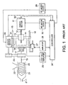
- the illustrated motor-driven injection molding machine carries out a filling of molten resin by converting rotational motion of a servomotor into linear or reciprocating motion using a ball screw and a nut.
- FIG. 1 rotation of an injection servomotor 11 is transmitted to a ball screw 12.
- a nut 13 is fixed to a pressure plate 14 such that it advances and is retracted in response to the rotation of the ball screw 12.
- the pressure plate 14 is movable along guide bars 15 and 16 fixed to a base frame (not shown).
- the back and forth movement of the pressure plate 14 is transmitted to a screw 20 via a bearing 17, a load cell 18, and an injection shaft 19.
- the screw 20 is disposed within a heating cylinder 21 such that it is rotatable and movable in the axial direction.
- the heat cylinder 21 corresponding to the rear portion of the screw 20 is provided with a hopper 22 for feeding resin powder.
- the rotational motion of a screw-rotation servomotor 24 is transmitted to the injection shaft 19 via a coupling member 23 comprised of, for example, a belt and a pulley.
- a coupling member 23 comprised of, for example, a belt and a pulley.
- the screw 20 rotates as a result that the injection shaft 19 is rotationally driven by the screw-rotation servomotor 24.
- molten resin is trapped in the heating cylinder 21 at the head of the screw 20, namely, on the side of a nozzle 21-1 when the screw 20 goes back while rotating in the heating cylinder 21.
- the molten resin in the front of the screw 21 is then filled in a mold (not shown) and pressurized for molding.
- Force acting upon the molten resin is detected by the load cell 18 as reaction force, namely, pressure.
- the load cell 18 produces a pressure detected signal indicative of the pressure.
- the pressure detected signal is amplified by a load cell amplifier 25 into an amplified pressure signal which is then supplied to a controller 26'.
- a position detector 27 detects an amount of movement of the screw 20 to produce a position detected signal indicative of the amount of the movement of the screw 20.
- the position detected signal is amplified by a position amplifier 28 into an amplified position signal which is then supplied to the controller 26'.
- the controller 26' supplies first and second current (torque) commands to first and second motor drivers 29 and 30 depending on desired values set by an operator.
- the first motor driver 29 controls a rotation speed of the screw-rotation servomotor 24 by means of controlling a first driving current for the screw-rotation servomotor 24.
- the second motor driver 30 controls a rotation speed of the injection servomotor 11 by means of controlling a second driving current for the injection servomotor 11.
- the screw-rotation servomotor 24 is provided with a first encoder 31 for detecting a first rotation speed of the screw-rotation servomotor 24 to produce a first rotation speed signal indicative of the first rotation speed.
- the injection servomotor 11 is provided with a second encoder 32 for detecting a second rotation speed of the injection servomotor 11 to produce a second rotation speed signal indicative of the second rotation speed.
- the first and the second rotation speed signals are supplied to the controller 26'.
- the first rotation speed detected by the first encoder 31 is used for determining a rotation speed of the screw 20.
- Fig. 1 the configuration illustrated in Fig. 1 is for the sake of simplicity and convenience.
- a specific configuration of this example injection device is described in, for example, Japanese Unexamined Patent Publication of Tokkai No. Hei 9-174,626 or JP-A 9-174,626 .
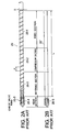
- the screw 20 is formed of four sections: a feed section 20-1, a compression section 20-2, a metering section 20-3, and a head section 20-4.
- the feed section 20-1 is for feeding the resin powder from the hopper 22 (Fig. 1) ahead a solid state or a partially molten state.
- the resin has temperature which is increased up to around a molten point at the feed section 20-1.
- the feed section 20-1 typically has a rod-shaped member 20' (Fig. 2B) of a generally constant diameter along the length thereof and a helical groove in the peripheral surface thereof.
- the resin powder Supplied from the feed section 20-1 to the compression section 20-2, the resin powder comprises a lot of resin grains which are spaced apart from each other. As a result, molten resin in the compression section 20-2 has an approximately half the volume of the resin powder.
- the compression section 20-2 is for reducing the space through which the resin powder is allowed to pass, in order to make up for the reduced volume. This compression can be achieved by means of tapering the rod-shaped member 20' at the position corresponding to the compression section 20-2 to make the helical groove shallow.
- the compression section 20-2 compresses the molten resin, enhances an exothermic effect caused by friction, and increases the pressure of the molten resin to push back to the hopper 22 air in the heating cylinder 21, moisture and volatile gas contained in the air and contaminated in the molten resin.
- the heat cylinder 21 has the resin pressure of the highest level in the compression section 20-2.
- the rod-shaped member 20' has the largest diameter in a region corresponding to the metering section 20-3.
- the metering section 20-3 has the shallowest helical groove formed in the rod-shaped member 20'.
- the molten resin is subjected to large shearing force in the metering section 20-3 and is heated to uniform temperature with an internal exothermic reaction. A predetermined amount of the molten resin is then fed towards the nozzle side in the heating cylinder 21.
- the feeding of the molten resin from the metering section 20-3 to the nozzle side is performed through a check valve ring 20-5 in the head section 20-4.
- the check valve ring 20-5 is located at a position in the vicinity of the left-hand side in the figure during the metering process. In this state, the molten resin can be fed from the metering section 20-3 to the nozzle side.
- the head section 20-4 is typically formed separately from the rod-shaped member 20'.
- the head section 20-4 has a male thread formed in the root portion thereof.
- the rod-shaped member 20' has a female thread formed in an end thereof.
- the head section 20-4 is coupled to the rod-shaped member 20' by means of engaging the male thread formed in the head section 20-4 with the female thread formed in the rod-shaped member 20'.
- the root portion of the head section 20-4 is significantly smaller in diameter than the rod-shaped member 20'.
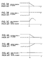
- Fig. 3A shows a waveform of a rotation speed N of the screw 20 while Fig. 3B shows a waveform of a retreat speed V of the screw 20.
- Fig. 3C shows a waveform of the back pressure P of the molten resin within the heating cylinder 21 that is metered ahead of the screw 20.
- a retreat of the screw 20 stops at a time instant T1 by controlling the position the screw 20, namely, the retreat speed V of the screw 20 is set equal to zero.
- the rotation speed N of the screw 20 does not become to zero after the time instant T1 as illustrated in Fig. 3A.
- the back pressure P of the metered molten resin within the heating cylinder 21 increases after the time instant T1 as illustrated in Fig. 3C.
- Fig. 4A shows a waveform of the rotation speed N of the screw 20 while Fig. 4B shows a waveform of the retreat speed V of the screw 20.
- Fig. 4C shows a waveform- of the back pressure P of the metered molten resin within the heating cylinder 21.
- the plasticization and metering process is completed at the time instant T1 in the similar manner as illustrated in Figs. 3A through 3C.
- the back pressure P of the metered molten resin within the heating cylinder 21 is monitored and then the pressure control is carried out so as to control the back pressure P of the metered molten resin within the heating cylinder 21 at a constant as illustrated in Fig.
- depressurization due to suck back may be carried out on and immediately after the completion of the plasticization and metering process.
- the screw position is determined in the similar manner as illustrated in Figs. 3A through 3C.
- the molten resin leaks to the nozzle side through the check valve ring 20-5 caused by a residual higher pressure in the heating cylinder 21.
- in as much as such residual pressure is not constant, it cannot be previously taken into consideration; variations in a leakage amount from heating cylinder 21 through check valve ring 20-5 to the nozzle side varies for each injection molding and it results in an inaccurate metered amount.
- control system for the screw-rotation servomotor 24 and the injection servomotor 11 in the motor-driven injection molding machine according a first embodiment of the present invention.
- the illustrated control system comprises first through third control subsystems C1, C2, and C3 which are called a rotation speed open loop control subsystem, a pressure feedback loop control subsystem, and a position feedback loop control subsystem, respectively.
- the rotation speed open loop control subsystem C1 is a control subsystem for controlling the screw-rotation servomotor 24 in response to a screw rotation speed command value N r for the screw 20.
- the pressure feedback loop control subsystem C2 is a control subsystem for controlling, in response to a pressure difference between a pressure command value P r and a pressure detected value P fb , either the injection servomotor 11 or the screw-rotation servomotor 24.
- the position feedback loop control subsystem C3 is a control subsystem for controlling, in response to a position difference between a screw position command value S r and a screw position detected value S fb , the injection servomotor 11.
- the controller 26 comprises a command setting section 40, first and second subtracters 41 and 42, first and second compensators 46 and 47, and first and second switches SW1 and SW2.
- the command setting section 40 produces a screw rotation speed command indicative of the screw rotation speed command value N r , a pressure command indicative of the pressure command value P r , and a screw position command indicative of the screw position command value S r .
- the controller 26 is supplied from the load cell 18 through the load cell amplifier 25 with the amplified pressure signal indicative of the pressure detected value P fb .
- the controller 26 is supplied from the position detector 27 through the position amplifier 28 with the amplified position signal indicative of the screw position detected value S fb .
- the pressure command indicative of the pressure command value P r is supplied to the first subtracter 41 which is supplied with the amplified pressure signal indicative of the pressure detected value P fb .
- the first subtracter 41 subtracts the pressure detected value P fb indicated by the amplified pressure signal from the pressure command value P r indicated by the pressure command to calculate the pressure difference between the pressure command value P r and the pressure detected value P fb .
- the first subtracter 41 produces a first subtraction result signal indicative of the pressure difference.
- the first subtraction result signal is supplied to the first compensator 46.
- the first compensator 46 compensates the first subtraction result signal to produce a first compensated signal.
- the screw position command indicative of the screw position command value S r is supplied to the second subtracter 42 which is supplied with the amplified position signal indicative of the screw position detected value S fb .
- the second subtracter 42 subtracts the screw position detected value S fb indicated by the amplified position signal from the screw position command value S r indicated by the screw position command to calculate the position difference between the screw position command value S r and the screw position detected value S fb .
- the second subtracter 42 produces a second subtraction result signal indicative of the position difference.
- the second subtraction result signal is supplied to the second compensator 47.
- the second compensator 47 compensates the second subtraction result signal to produce a second compensated signal.
- the first compensated signal is supplied to the first and the second switches SW1 and SW2.
- the second compensated signal is supplied to the second switch SW2.
- the first switch SW1 is supplied with the screw rotation speed command indicative of the screw rotation speed command value N r from the command setting section 40.
- the first switch SW1 selects, as a first selected signal, one of the screw rotation speed command and the first compensated signal.
- the first switch SW1 supplies the first motor driver 29 with the first selected signal as the first actuating command.
- the second switch SW2 selects, as a second selected signal, one of the first and the second compensated signal.
- the second switch SW2 supplies the second motor driver 30 with the second selected signal as the second actuating command. In the manner which will later become clear, the first and the second switches SW1 and SW2 are interlocked with each other.
- a combination of the command setting section 40, the first switch SW1, the first motor driver 29, and the screw-rotation serve-motor 24 serves as the rotation speed open loop control subsystem C1.
- a combination of the command setting section 40, the first subtracter 41, the first compensator 46, the second switch SW2, the second motor driver 30, the injection servomotor 11, the load cell 18, and the load cell amplifier 25 acts as the pressure feedback loop control subsystem C2.
- a combination of the command setting section 40, the first subtracter 41, the first compensator 46, the first switch SW1, the first motor driver 29, the screw-rotation servomotor 24, the load cell 18, and the load cell amplifier 25 also acts as the pressure feedback loop control subsystem C2.
- a combination of the command setting section 40, the second subtracter 42, the second compensator 47, the second switch SW2, the second motor driver 30, the injection serve-motor 11, the position detector 27, and the position amplifier 28 is operable as the position feedback loop control subsystem C3.
- the description will proceed to operation of the control system illustrated in Fig. 5. Attention will be directed to the plasticization and metering process in the motor-driven injection molding machine.
- the first and the second switches SW1 and SW2 are put into a state as illustrated in Fig. 5. That is, the screw rotation speed command indicative of the screw rotation speed command value N r is supplied to the first motor driver 29 through the first switch SW1 as the first actuating command.
- the first compensated signal is supplied to the second motor driver 30 through the second switch SW2 as the second actuating command.
- the rotation speed open loop control subsystem C1 carries out rotation speed control of the screw-rotation servomotor 24 by supplying the screw rotation speed command indicative of the screw rotation speed command value N r to the first motor driver 29 through the first switch SW1 as the first actuating command.
- the pressure feedback loop control subsystem C2 carries out pressure control of the injection servomotor 11 by supplying the first subtraction result signal indicative of the pressure difference between pressure command value P r and the pressure detected value P fb to the second motor driver 30 through the first compensator 46 and the second switch SW2 as the second actuating command.
- the first and the second switches SW1 and SW2 are switched from the state as illustrated in Fig. 5. That is, the first compensated signal is supplied to the first motor driver 29 through the first switch SW1 as the first actuating command. In addition, the second compensated signal is supplied to the second motor driver 30 through the second switch SW2 as the second actuating command. Furthermore, the command setting section 40 produces, as the pressure command, a pressure command indicative of a depressurization target value P r which is less than the pressure command value P r during the plasticization and metering process.
- the pressure feedback loop control subsystem C2 carries out pressure control of the screw-rotation servomotor 24 by supplying, as the first actuating command, the first subtraction result signal indicative of the pressure difference between the depressurization target value P r ' and the pressure detected value P fb to the first motor driver 29 through the first compensator 46 and the first switch SW1.
- the position feedback loop control subsystem C3 carries out position control of the injection servomotor 11 by supplying, as the second actuating command, the second subtraction result signal indicative of the position difference between the screw position command value S r and the screw position detected value S fb to the second motor driver 30 through the second compensator 47 and the second switch SW2.
- a combination of the command setting section 40, the first subtracter 41, the first compensator 66, and the first switch SW1 serves as a reverse rotating arrangement for rotating, in the response to the pressure detected signal, the screw 20 in the opposite direction by supplying the first actuating command to the first motor driver 29 on and immediately after the completion of the plasticization and metering process to carry out depressurization of the molten resin in the heating cylinder 21 that is metered ahead of the screw 20.
- a combination of the command setting section 40, the second subtracter 42, the second compensator 47, and the second switch SW2 acts as a positioning arrangement for positioning, in response to the position detected signal, the screw 20 at a metering position by supplying the second actuating command to the second motor driver 30 on and immediately after the completion of the plasticization and metering process.
- the screw-rotation servomotor 24 is controlled on the basis of the screw rotation speed command value N r to carry out a metering of the molten resin and the injection servomotor 11 is controlled on the basis of the pressure difference between the pressure command value P r and the pressure detected value P fb to carry out control of the back pressure of the metered molten resin in the heating cylinder 21.
- the first and the second switches SW1 and SW2 are switched from the state as illustrated in Fig. 5.
- the position feedback loop control subsystem C3 positions the screw position so as to locate a metering position given by the screw position command value S r on and immediately after the completion of the plasticization and metering process.
- the pressure feedback loop control subsystem C2 monitors the pressure detected value P fb detected by the load cell 18 and carries out the depressurization of the metered molten resin within the heating cylinder 21 metered ahead of the screw 20 by making the screw 20 rotate in the opposite direction in response to the pressure detected value P fb .
- the reason why the screw 20 rotates in the opposite direction is that the depressurization target value P r given on the completion of the plasticization and metering process is less than the pressure detected value P fb .
- the rotation speed of the screw-rotation servomotor 24 in the opposite direction is determined in accordance with the pressure difference between the monitored pressure detected value P fb and a predetermined value or the depressurization target value P r '.
- the control system illustrated in Fig. 5 makes the screw 20 rotate in the opposite direction until the monitored pressure detected value P fb is equal to the depressurization target value P r '.
- the rotation speed of the screw-rotation servomotor 24 in the opposite direction may preferably be restricted to the upper limit which is preliminarily set. This is because, if the rotation speed of the screw-rotation servomotor 24 is too high, the depressurization is too large.
- a time interval for which the screw 20 rotates in the opposite direction may preferably be restricted to the upper limit which is also preliminarily set. This reason is as follows. When the back pressure of the metered molten resin within the heating cylinder 21 decreases caused by the depressurization, the check valve ring 20-5 (Fig. 2) stops the molten resin from flowing back to the metering section 20-3 side in the heating cylinder 21.
- a controller 26A is provided with a limiter 48 to the output side of the first compensator 46, as a second embodiment of the present invention illustrated in Fig. 6.
- the limiter 48 limits the first compensated signal to produce a limited signal.
- the limited signal is supplied to input terminals of the first and the second switches SW1 and SW2.
- a combination of the command setting section 40, the first subtracter 41, the first compensator 66, the limiter 48, and the first switch SW1 serves as a reverse rotating arrangement for rotating, in the response to the pressure detected signal, the screw 20 in the opposite direction by supplying the first actuating command to the first motor driver 29 on and immediately after the completion of the plasticization and metering process to carry out depressurization of the molten resin in the heating cylinder 21 that is metered ahead of the screw 20.
- control system for the screw-rotation servomotor 24 and the injection servomotor 11 in the motor-driven injection molding machine according to a third embodiment of the present invention.
- the illustrated control system is similar in structure and operation to the control system illustrated in Fig. 5 except that the controller is modified from that illustrated in Fig. 5 as will later become clear.
- the controller is therefore depicted as 26B.
- similar parts are attached with the same reference symbols and description thereof is omitted.
- the controller 26B is similar in structure and operation to the controller 26 illustrated in Fig. 5 except that the controller 26B comprises a comparator 49 in place of a combination of the first subtracter 41 and the first compensator 46.
- the comparator 49 has a noninverting input terminal supplied with the pressure command indicative of the pressure command value P r and an inverting input terminal supplied with the amplified pressure signal indicative of the pressure detected value P fb .
- the comparator 49 compares the pressure command value P r indicated by the pressure command with the pressure detected value P fb indicated by the amplified pressure signal to produce a comparison result signal indicative of a comparison result between the pressure command value P r and the pressure detected value P fb .
- the comparison result signal is supplied to the input terminals of the first and the second switches SW1 and SW2.
- the comparator 49 produces, as the comparison result signal, a signal having a logic low level.
- the comparator 49 produces, as the comparison result signal, a signal having a logic high level.
- the first and the second switches SW1 and SW2 are switched from the state as illustrated in Fig. 7.
- the command setting section 40 produces the pressure command indicative of the depressurization target value P r '.
- the comparator 49 produces, as the comparison result signal, the signal having the logic low level which is supplied to the first motor driver 29 through the first switch SW1 on and immediately after the completion of the plasticization and metering process.
- the screw-rotation servomotor 24 makes the screw 20 rotate in the opposite direction on and immediately after the completion of the plasticization and metering process until the pressure detected value P fb coincides with the depressurization target value P r '. In this event, the screw-rotation servomotor 24 makes the screw 20 rotate in the opposite direction at the rotation speed having a fixed value.
- a combination of the command setting section 40, the comparator 49, and the first switch SW1 is operable as a reverse rotating arrangement for rotating, in the response to the pressure detected signal, the screw 20 in the opposite direction by supplying the first actuating command to the first motor driver 29 on and immediately after the completion of the plasticization and metering process to carry out depressurization of the molten resin in the heating cylinder 21 that is metered ahead of the screw 20.
- controller may be embodied in a microcomputer which simply changes the subroutines for controlling the rotation of the screw.
Landscapes
- Engineering & Computer Science (AREA)
- Manufacturing & Machinery (AREA)
- Mechanical Engineering (AREA)
- Injection Moulding Of Plastics Or The Like (AREA)
Claims (18)
- Procédé d'actionnement d'une machine de moulage par injection comprenant un dispositif d'injection avec un servomoteur de rotation de vis (24) et un servomoteur d'injection (11) pour entraîner un arbre d'injection (19), le dispositif d'injection étant muni d'une cellule de chargement (18) pour détecter une contre-pression de la résine fondue mesurée en amont d'une vis (20), la machine de moulage par injection comprenant un contrôleur (26, 26A, 26B) pour contrôler, en réponse à une valeur détectée de la cellule de chargement, chacun des servomoteurs (11, 24), ce procédé comprenant les étapes suivantes :(a) disposer de la résine en poudre dans un cylindre de chauffage (21) pour fondre la résine en poudre ; et(b) faire tourner la vis (20) disposée dans le cylindre de chauffage (21) dans une première direction pour fournir la résine fondue à une buse (21-1) du cylindre de chauffage en entraînant le servomoteur de rotation de vis (24) en effectuant une commande de contre-pression en commandant le servomoteur d'injection (11) sur la base de la valeur de pression détectée par la cellule de chargement (18) pendant un processus de plastification et de dosage,
caractérisé en ce qu'il comprend en outre l'étape suivante :(c) faire tourner la vis (20) dans le cylindre de chauffage (21) dans une direction opposée à la première direction en entraînant le servomoteur de rotation de vis (24) en surveillant la valeur de pression détectée par la cellule de chargement (18) de façon à atteindre une pression désirée de la résine fondue au niveau de la buse (21-1) du cylindre de chauffage à l'achèvement du processus de plastification et de dosage. - Procédé selon la revendication 1, caractérisé en ce que l'étape (c) comprend une rotation de la vis (20) en sens opposé de la première direction en réponse à la pression de la résine fondue au niveau de la buse (21-1) du cylindre de chauffage.
- Procédé selon la revendication 1 ou 2, caractérisé en ce que l'étape (b) comprend une rotation de la vis à une vitesse constante dans la première direction.
- Procédé selon l'une quelconque des revendications 1 à 3, caractérisé en ce qu'il comprend en outre :(d) pendant l'étape (b), régler la position (Sfb) de la vis (20) le long de son axe longitudinal.
- Procédé selon la revendication 4, caractérisé en ce que l'étape (d) comprend un réglage de la position (Sfb) de la vis selon son axe longitudinal en réponse à la pression (Pfb) de la résine fondue au niveau de la buse (21-1) du cylindre de chauffage.
- Procédé selon la revendication 4 ou 5, caractérisé en ce que l'étape (d) comprend le contrôle de la pression de la résine fondue au niveau de la buse (21-1) du cylindre de chauffage en réglant la position de la vis (20) selon son axe longitudinal.
- Procédé selon l'une quelconque des revendications 4 à 6, caractérisé en ce que :l'étape (d) comprend le réglage de la position (Sfb) de la vis selon son axe longitudinal pour atteindre une pression désirée (Pr) de la résine fondue au niveau de la buse (21-1) du cylindre de chauffage (21), la pression désirée à la fin des étapes (b) étant une première pression désirée ; etl'étape (c) comprend une rotation de la vis dans la direction opposée à la première direction pour atteindre une seconde pression désirée (Pr') de la résine fondue au niveau de la buse du cylindre de chauffage ; etla première pression désirée (Pr) est supérieure à la seconde pression désirée (Pr').
- Procédé selon la revendication 5, caractérisé en ce que :l'étape (d) comprend le contrôle de la position (Sfb) de la vis selon son axe longitudinal en comparant la pression désirée (Pr) de la résine fondue au niveau de la buse du cylindre de chauffage à la pression réelle (Pfb) de la résine fondue au niveau de la buse du cylindre de chauffage ; etl'étape (c) comprend la rotation de la vis dans la direction opposée à la première direction en comparant une pression désirée (Pr) de la résine fondue au niveau de la buse du cylindre de chauffage à la pression réelle (Pfb) de la résine fondue au niveau de la buse du cylindre de chauffage.
- Procédé selon la revendication 1 ou 2, caractérisé en outre en ce qu'il comprend :(d) pendant l'étape (c), commander la position (Sfb) de la vis selon son axe longitudinal pour atteindre une position désirée (Sr).
- Procédé selon la revendication 9, caractérisé en ce qu'il comprend en outre :(e) pendant l'étape (b), commander la pression de la résine fondue au niveau de la buse du cylindre de chauffage en réglant la position de la vis selon son axe longitudinal.
- Procédé selon l'une quelconque des revendications 1 à 10, caractérisé en ce que l'étape (c) comprend une rotation de la vis (20) dans le cylindre de chauffage (21) dans la direction opposée à la première direction pendant une durée maximum.
- Procédé selon l'une quelconque des revendications 1 à 11, caractérisé en ce que les étapes (b) et (c) font tourner la vis à une vitesse allant jusqu'à une vitesse maximum prédéterminée.
- Contrôleur (26) pour une machine de moulage par injection, la machine de moulage par injection comprenant un cylindre de chauffage (21) pour fondre de la poudre de résine pour créer de la résine fondue, une vis (20) disposée dans le cylindre de chauffage pour fournir la résine fondue à une buse (21-1) du cylindre de chauffage, un premier moteur (24) actionnable pour faire tourner la vis (20) et un second moteur (11) actionnable pour déplacer la vis (20) selon son axe longitudinal, le contrôleur (26) comprenant :une première sortie (29) vers le premier moteur pour commander la vitesse de rotation de la vis (20) ;une seconde sortie (30) vers le second moteur pour commander la position de la vis (20) selon son axe longitudinal ;caractérisé en ce que la première sortie fournit un signal ayant une première valeur pour doser la résine fondue fournie par la buse (21-1) du cylindre de chauffage (21) en commandant la rotation de la vis (20) vers la première direction, et fournit un signal ayant une seconde valeur après que la résine fondue a été dosée au niveau de la buse (21-1) du cylindre de chauffage pour commander la rotation de la vis dans une direction opposée à la première direction.
- Machine de moulage par injection commandée par moteur comprenant :un cylindre de chauffage (21) pour chauffer la résine en poudre pour fondre la résine en poudre en une résine fondue ;une vis (20) disposée dans le cylindre de chauffage pour fournir la résine fondue dans le cylindre de chauffage vers l'avant pour doser la résine fondue pour créer une contre-pression dans la résine fondue ;un servomoteur de rotation de vis (24) couplé en fonctionnement à la vis pour faire tourner la vis ;un servomoteur d'injection (11) couplé en fonctionnement à la vis pour entraîner la vis dans une direction axiale pour injecter la résine fondue dosée dans le cylindre de chauffage (21) vers l'avant ;une commande (29) du premier moteur commandant la rotation de la vis ;une commande (30) du second moteur commandant l'injection ;une cellule de chargement (18) pour détecter la contre-pression de la résine fondue dans le cylindre de chauffage (21) pour produire un signal de pression détecté (Pfb) ;un détecteur de position (27) pour détecter la position de la vis (20) pour produire un signal de position détecté (Sfb) ; etun contrôleur (26) commandant, en réponse au signal de pression détecté (Pfb) et au signal de position détecté (Sfb), le servomoteur de rotation de vis (24) et le servomoteur d'injection (11) par l'intermédiaire des commandes de premier et second moteurs (29, 30) en fournissant aux commandes de premier et second moteurs des première et seconde commandes d'actionnement, respectivement,caractérisé en ce que le contrôleur (26) comprend :un moyen de mise en rotation connecté à la cellule de chargement (18) pour faire tourner la vis (20) dans une première direction pendant un processus de plastification et de dosage et ensuite, en réponse au signal de pression détecté, pour faire tourner la vis en sens opposé de façon à obtenir une pression désirée da la résine fondue au niveau de la buse (21-1) du cylindre de chauffage (21) en fournissant un premier ordre d'actionnement à la commande (29) du premier moteur lors de ou immédiatement après l'achèvement du processus de plastification et de dosage, réduisant ainsi la pression de la résine fondue dans le cylindre de chauffage (21) qui est dosée en amont de la vis ; etun moyen de positionnement, connecté au détecteur de position (27) pour positionner, en réponse au signal de position détecté (Sfb), la vis à une position de dosage en fournissant le second ordre d'actionnement à la commande (30) du second moteur lors de ou immédiatement après l'achèvement du processus de plastification et de dosage.
- Machine de moulage par injection selon la revendication 14, caractérisée en ce que le moyen de rotation comprend :un moyen de réglage de pression (40) pour produire une commande de pression (Pr') indicative d'une valeur cible de réduction de pression lors de ou immédiatement après l'achèvement du processus de plastification et de dosage ;un soustracteur (41) connecté au moyen de réglage de pression (40) et à la cellule de chargement (18) pour soustraire la valeur de pression détectée indiquée par le signal de pression détecté (Pfb) de la valeur cible de réduction de pression indiquée dans la commande de pression (Pr') pour produire un signal de résultat de soustraction indicatif d'une différence de pression entre la valeur cible de réduction de pression et la valeur de pression détectée ;un compensateur (46) connecté au soustracteur (41) pour compenser le signal de résultat de soustraction pour produire un signal compensé ; etun moyen d'alimentation (SW1) connecté au compensateur et à la commande (29) du premier moteur pour fournir à la commande de premier moteur le signal compensé en tant que premier ordre d'actionnement lors de ou immédiatement après l'achèvement du processus de plastification et de dosage.
- Machine de moulage par injection selon la revendication 14, caractérisée en ce que le moyen de rotation comprend :un moyen de réglage de pression (40) pour produire une commande de pression indicative d'une valeur cible de réduction de pression (Pr') lors de ou immédiatement après l'achèvement du processus de plastification et de dosage ;un soustracteur (41) connecté au moyen de réglage de pression (40) et à la cellule de chargement (18) pour soustraire la valeur de pression détectée indiquée par le signal de pression détecté (Pfb) de la valeur cible de réduction de pression indiquée dans la commande de pression (Pr') pour produire un signal de résultat de soustraction indicatif d'une différence de pression entre la valeur cible de réduction de pression et la valeur de pression détectée ;un compensateur (46) connecté au soustracteur (41) pour compenser le signal de résultat de soustraction pour produire un signal compensé ; etun limiteur (48) connecté au compensateur (46) pour limiter le signal compensé ; etun moyen d'alimentation (SW1) connecté au limiteur (48) et à la commande (29) de premier moteur pour fournir à la commande de premier moteur le signal limité en tant que premier ordre d'actionnement lors de ou immédiatement après l'achèvement du processus de plastification et de dosage.
- Machine de moulage par injection selon la revendication 14, caractérisée en ce que le moyen de rotation comprend :un moyen de réglage de pression (40) pour produire une commande de pression indicative d'une valeur cible de réduction de pression (Pr') lors de ou immédiatement après l'achèvement du processus de plastification et de dosage ;un comparateur (49) ayant une borne d'entrée non inverseuse recevant le signal d'ordre de pression (Pr') et une borne d'entrée inverseuse recevant le signal de pression détecté (Pfb), le comparateur (49) comparant la valeur de pression détectée indiquée par le signal de pression détecté à la valeur cible de réduction de pression indiquée par l'ordre de pression pour produire un signal de résultat de comparaison indicatif du résultat de la comparaison entre la valeur cible de réduction de pression et la valeur de pression détectée ; etun moyen d'alimentation (SW1) connecté au comparateur (49) et à la commande (29) de premier moteur pour fournir à la commande de premier moteur le signal de résultat de comparaison en tant que premier ordre d'actionnement lors de ou immédiatement après l'achèvement du processus de plastification et de dosage.
- Machine de moulage par injection selon la revendication 14, caractérisée en ce que le moyen de positionnement comprend :un moyen de réglage de position (40) pour produire un ordre de position indicatif d'une valeur d'ordre de position de vis (Sr) lors de ou immédiatement après l'achèvement du processus de plastification et de dosage ;un soustracteur (42) connecté au moyen de réglage de position et au détecteur de position (27) pour soustraire la valeur détectée de position de vis (Sfb) indiquée par le signal de position détecté de la valeur d'ordre de position de vis (Sr) indiquée par l'ordre de position pour produire un signal de résultat de soustraction indicatif de la différence de position entre la valeur d'ordre de position de vis et la valeur détectée de position de vis ;un compensateur (47) connecté au soustracteur pour compenser le signal de résultat de soustraction pour produire un signal compensé ; etun moyen d'alimentation (SW2) connecté au compensateur (47) et à la commande (30) de second moteur pour fournir à la commande de second moteur le signal compensé en tant que second ordre d'actionnement lors de ou immédiatement après l'achèvement du processus dé plastification et de dosage.
Applications Claiming Priority (2)
| Application Number | Priority Date | Filing Date | Title |
|---|---|---|---|
| JP16993198A JP3250180B2 (ja) | 1998-06-17 | 1998-06-17 | 電動射出成形機の可塑化/計量工程における除圧方法 |
| JP16993198 | 1998-06-17 |
Publications (3)
| Publication Number | Publication Date |
|---|---|
| EP0965428A2 EP0965428A2 (fr) | 1999-12-22 |
| EP0965428A3 EP0965428A3 (fr) | 2001-12-05 |
| EP0965428B1 true EP0965428B1 (fr) | 2007-08-15 |
Family
ID=15895593
Family Applications (1)
| Application Number | Title | Priority Date | Filing Date |
|---|---|---|---|
| EP99111090A Expired - Lifetime EP0965428B1 (fr) | 1998-06-17 | 1999-06-17 | Procédé de dépressurisation lors de la plastification et du dosage pour une machine de moulage par injection |
Country Status (9)
| Country | Link |
|---|---|
| US (1) | US6340439B1 (fr) |
| EP (1) | EP0965428B1 (fr) |
| JP (1) | JP3250180B2 (fr) |
| KR (1) | KR100473928B1 (fr) |
| CN (1) | CN1118361C (fr) |
| AT (1) | ATE369965T1 (fr) |
| DE (1) | DE69936821T2 (fr) |
| SG (1) | SG82618A1 (fr) |
| TW (1) | TW461851B (fr) |
Families Citing this family (31)
| Publication number | Priority date | Publication date | Assignee | Title |
|---|---|---|---|---|
| KR100732786B1 (ko) * | 2000-02-07 | 2007-06-27 | 가부시키가이샤 메이키 세이사쿠쇼 | 사출 성형기 |
| US6554774B1 (en) | 2000-03-23 | 2003-04-29 | Tensys Medical, Inc. | Method and apparatus for assessing hemodynamic properties within the circulatory system of a living subject |
| JP3776672B2 (ja) * | 2000-03-29 | 2006-05-17 | 日精樹脂工業株式会社 | 射出成形機のモータ駆動装置 |
| JP4459467B2 (ja) * | 2000-10-31 | 2010-04-28 | 三菱重工プラスチックテクノロジー株式会社 | 電動射出成形機及び電動射出成形機の射出速度・射出圧力制御方法 |
| DE10058866B4 (de) * | 2000-11-27 | 2005-02-10 | Siemens Ag | Einspritzaggregat für eine Spritzgiessmaschine |
| US20020100992A1 (en) * | 2000-12-02 | 2002-08-01 | Battenfeld Service Gmbh | Method for operating an injection unit for an injection molding machine |
| JP3652681B2 (ja) * | 2002-11-08 | 2005-05-25 | ファナック株式会社 | 射出成形機における計量方法及び制御装置 |
| JP3805308B2 (ja) | 2003-01-17 | 2006-08-02 | ファナック株式会社 | 射出成形機 |
| JP3892852B2 (ja) * | 2004-02-17 | 2007-03-14 | ファナック株式会社 | 電動射出成形機の負荷検出装置 |
| US7946994B2 (en) * | 2004-10-07 | 2011-05-24 | Tensys Medical, Inc. | Compact apparatus and methods for non-invasively measuring hemodynamic parameters |
| US7686604B2 (en) * | 2004-12-20 | 2010-03-30 | Mgs Mfg. Group, Inc. | Coaxial injector screw providing improved small shot metering |
| JP4264427B2 (ja) * | 2005-05-30 | 2009-05-20 | 日精樹脂工業株式会社 | 射出成形機の計量方法 |
| CN100411843C (zh) * | 2006-07-31 | 2008-08-20 | 中北大学 | 多用途高分子材料成型机 |
| JP4231517B2 (ja) * | 2006-09-12 | 2009-03-04 | 日精樹脂工業株式会社 | 射出成形機の計量制御方法 |
| JP4137975B2 (ja) | 2006-12-26 | 2008-08-20 | ファナック株式会社 | 射出成形機、及び射出成形機における逆回転工程の制御条件調整方法 |
| ITMC20070020U1 (it) * | 2007-04-18 | 2008-10-19 | Ohg Galletti O M G Srl | Mescolatore per calcestruzzo ed altri simili impasti suscettibile di un agevole e sicura pulizia interna. |
| KR100931805B1 (ko) * | 2008-01-28 | 2009-12-14 | 엘에스엠트론 주식회사 | 전동식 사출 성형기의 사출 축 제어 방법 |
| JP5801128B2 (ja) * | 2011-07-26 | 2015-10-28 | 住友重機械工業株式会社 | 射出成形機 |
| JP5762869B2 (ja) * | 2011-07-26 | 2015-08-12 | 住友重機械工業株式会社 | 射出成形機 |
| WO2017011530A1 (fr) * | 2015-07-15 | 2017-01-19 | iMFLUX Inc. | Moulage par injection avec une bague de vérification des fuites |
| EP3708331B1 (fr) * | 2015-12-04 | 2022-08-03 | Extrude to Fill, Inc. | Machine de moulage et procédé de moulage d'une pièce |
| TWI680048B (zh) * | 2016-03-04 | 2019-12-21 | 台達電子工業股份有限公司 | 注塑機控制系統及方法 |
| KR20180072338A (ko) | 2016-12-21 | 2018-06-29 | 엘에스엠트론 주식회사 | 사출성형공정 |
| JP7260424B2 (ja) * | 2019-07-04 | 2023-04-18 | ファナック株式会社 | 射出成形機 |
| JP7256718B2 (ja) * | 2019-09-06 | 2023-04-12 | ファナック株式会社 | 射出成形機の制御装置及び制御方法 |
| JP7277323B2 (ja) * | 2019-09-18 | 2023-05-18 | ファナック株式会社 | 射出成形機の制御装置および制御方法 |
| JP7294966B2 (ja) * | 2019-09-18 | 2023-06-20 | ファナック株式会社 | 射出成形機の制御装置および制御方法 |
| JP7277332B2 (ja) * | 2019-09-30 | 2023-05-18 | ファナック株式会社 | 射出成形機の制御装置および制御方法 |
| AT523150B1 (de) * | 2019-11-28 | 2021-06-15 | Engel Austria Gmbh | Verfahren zur Beeinflussung einer Rückstaulänge und/oder einer Schneckenrücklaufgeschwindigkeit |
| JP7396884B2 (ja) * | 2019-12-11 | 2023-12-12 | ファナック株式会社 | 射出成形機の制御装置および制御方法 |
| JP2024104804A (ja) * | 2023-01-25 | 2024-08-06 | 株式会社日本製鋼所 | 射出成形機、および射出成形機の診断方法 |
Family Cites Families (16)
| Publication number | Priority date | Publication date | Assignee | Title |
|---|---|---|---|---|
| DE3203763C2 (de) * | 1982-02-04 | 1990-09-13 | Klöckner-Werke AG, 4100 Duisburg | Plastifizier- und Einspritzeinheit für Spritzgießmaschinen |
| JPS60174623A (ja) * | 1984-02-21 | 1985-09-07 | Toshiba Mach Co Ltd | 射出成形機 |
| KR870001279B1 (ko) * | 1984-06-20 | 1987-06-30 | 최정자 | 필수성분과 미량요소를 함유하는 식물생육제 |
| JPS6161818A (ja) * | 1984-09-04 | 1986-03-29 | Fanuc Ltd | 射出成形機のスクリユ回転制御方式 |
| JPS61220817A (ja) * | 1985-03-28 | 1986-10-01 | Fanuc Ltd | 射出成形機の計量混練方式 |
| JPS6330227A (ja) * | 1986-07-24 | 1988-02-08 | Fanuc Ltd | 計量終了時におけるスクリュ−停止制御方式 |
| JPH01148525A (ja) * | 1987-12-04 | 1989-06-09 | Japan Steel Works Ltd:The | 電動射出成形機の可塑化装置 |
| US4879077A (en) * | 1988-02-29 | 1989-11-07 | Nissei Jushi Kogyo Kabushiki Kaisha | Control method of injection molding machine |
| JP2544657B2 (ja) * | 1988-10-31 | 1996-10-16 | ファナック株式会社 | 電動式射出成形機における背圧制御方法 |
| US5028373A (en) * | 1990-01-18 | 1991-07-02 | Toyo Machinery & Metal Co., Ltd. | Method for controlling injection unit of injection molding machine |
| JP2650790B2 (ja) * | 1991-01-11 | 1997-09-03 | 東洋機械金属株式会社 | 射出成形機の制御方法 |
| US5421712A (en) * | 1993-10-05 | 1995-06-06 | Industrial Technology Research Institute | Screw rotating and advancing device for an injection molding machine |
| JP2814212B2 (ja) * | 1995-07-19 | 1998-10-22 | 日精樹脂工業株式会社 | 射出装置における射出方法 |
| JP2880675B2 (ja) * | 1995-12-26 | 1999-04-12 | 住友重機械工業株式会社 | 電動射出成形機 |
| JPH09300410A (ja) * | 1996-05-13 | 1997-11-25 | Japan Steel Works Ltd:The | 電動射出成形機の背圧制御方法 |
| JP3111413B2 (ja) * | 1996-07-04 | 2000-11-20 | 住友重機械工業株式会社 | 射出装置 |
-
1998
- 1998-06-17 JP JP16993198A patent/JP3250180B2/ja not_active Expired - Fee Related
-
1999
- 1999-06-16 KR KR10-1999-0022553A patent/KR100473928B1/ko not_active Expired - Fee Related
- 1999-06-17 DE DE69936821T patent/DE69936821T2/de not_active Expired - Lifetime
- 1999-06-17 EP EP99111090A patent/EP0965428B1/fr not_active Expired - Lifetime
- 1999-06-17 SG SG9902950A patent/SG82618A1/en unknown
- 1999-06-17 CN CN99109069A patent/CN1118361C/zh not_active Expired - Fee Related
- 1999-06-17 US US09/334,670 patent/US6340439B1/en not_active Expired - Lifetime
- 1999-06-17 AT AT99111090T patent/ATE369965T1/de not_active IP Right Cessation
- 1999-06-17 TW TW088110249A patent/TW461851B/zh not_active IP Right Cessation
Also Published As
| Publication number | Publication date |
|---|---|
| JP2000000858A (ja) | 2000-01-07 |
| KR20000006223A (ko) | 2000-01-25 |
| EP0965428A2 (fr) | 1999-12-22 |
| ATE369965T1 (de) | 2007-09-15 |
| KR100473928B1 (ko) | 2005-03-07 |
| CN1239032A (zh) | 1999-12-22 |
| US6340439B1 (en) | 2002-01-22 |
| DE69936821T2 (de) | 2008-05-15 |
| JP3250180B2 (ja) | 2002-01-28 |
| DE69936821D1 (de) | 2007-09-27 |
| SG82618A1 (en) | 2001-08-21 |
| CN1118361C (zh) | 2003-08-20 |
| EP0965428A3 (fr) | 2001-12-05 |
| TW461851B (en) | 2001-11-01 |
Similar Documents
| Publication | Publication Date | Title |
|---|---|---|
| US6340439B1 (en) | Depressurization method in plasticization and metering process for a motor-driven injection molding machine | |
| EP1362684B1 (fr) | Système de commande pour une presse à injecter et procédé de commande d'une presse à injecter | |
| EP1418039B1 (fr) | Procédé de dosage et dispositif de contrôle d'une machine de moulage par injection | |
| EP1418040B1 (fr) | Dispositif de contrôle d'une machine de moulage par injection | |
| US6244848B1 (en) | Controller for adjusting zero point for load cell in a motor-driven injection molding machine | |
| US6416694B1 (en) | Injection controlling method for an injection molding machine | |
| EP1072387B1 (fr) | Procédé et dispositif pour ajuster le zéro d'un capteur de pression d'une machine de moulage par injection | |
| EP0965430B1 (fr) | Procédé de contrôle de l'entraínement de la vis extrudeuse d'une machine de moulage par injection | |
| KR100466521B1 (ko) | 성형품의 중량의 편차를 억제할 수 있는 사출성형기의제어방법 | |
| JP2002254470A (ja) | 電動式射出成形機におけるロードセルの零点調整方法 | |
| JP2638626B2 (ja) | 射出成形機のフィードバック制御方法 | |
| US20020005598A1 (en) | Method of controlling the screw of injection molding machine | |
| JP2628753B2 (ja) | 射出成形機のスクリュ後退速度制御装置 | |
| JP3052187B2 (ja) | 電動射出成形機の背圧制御方式 | |
| JP2992328B2 (ja) | 電動射出成形機の保圧制御装置 | |
| JP2919167B2 (ja) | 電動式射出成形機における射出制御方法 | |
| JP3240513B2 (ja) | 射出成形機のスクリュ回転数設定方法 | |
| JP2868139B2 (ja) | 射出成形機の射出制御方法および装置 | |
| JPH11129296A (ja) | 射出成形機の制御方法 | |
| JP3336301B2 (ja) | 射出装置及びその制御方法 | |
| JP2000006207A (ja) | 射出成形機のスクリュ回転立上げ方法 | |
| JP3245818B2 (ja) | 射出成形機のスクリュ回転設定方法 | |
| JPH06246801A (ja) | 射出成形機の射出制御方法 | |
| JPH04364919A (ja) | 射出成形機の制御方法 | |
| JPH059256B2 (fr) |
Legal Events
| Date | Code | Title | Description |
|---|---|---|---|
| PUAI | Public reference made under article 153(3) epc to a published international application that has entered the european phase |
Free format text: ORIGINAL CODE: 0009012 |
|
| AK | Designated contracting states |
Kind code of ref document: A2 Designated state(s): AT BE CH CY DE DK ES FI FR GB GR IE IT LI LU MC NL PT SE Kind code of ref document: A2 Designated state(s): AT CH DE FR GB IT LI |
|
| AX | Request for extension of the european patent |
Free format text: AL;LT;LV;MK;RO;SI |
|
| PUAL | Search report despatched |
Free format text: ORIGINAL CODE: 0009013 |
|
| AK | Designated contracting states |
Kind code of ref document: A3 Designated state(s): AT BE CH CY DE DK ES FI FR GB GR IE IT LI LU MC NL PT SE |
|
| AX | Request for extension of the european patent |
Free format text: AL;LT;LV;MK;RO;SI |
|
| 17P | Request for examination filed |
Effective date: 20020605 |
|
| AKX | Designation fees paid |
Free format text: AT CH DE FR GB IT LI |
|
| 17Q | First examination report despatched |
Effective date: 20020823 |
|
| GRAP | Despatch of communication of intention to grant a patent |
Free format text: ORIGINAL CODE: EPIDOSNIGR1 |
|
| GRAS | Grant fee paid |
Free format text: ORIGINAL CODE: EPIDOSNIGR3 |
|
| GRAA | (expected) grant |
Free format text: ORIGINAL CODE: 0009210 |
|
| AK | Designated contracting states |
Kind code of ref document: B1 Designated state(s): AT CH DE FR GB IT LI |
|
| REG | Reference to a national code |
Ref country code: GB Ref legal event code: FG4D |
|
| REG | Reference to a national code |
Ref country code: CH Ref legal event code: EP |
|
| REF | Corresponds to: |
Ref document number: 69936821 Country of ref document: DE Date of ref document: 20070927 Kind code of ref document: P |
|
| PG25 | Lapsed in a contracting state [announced via postgrant information from national office to epo] |
Ref country code: CH Free format text: LAPSE BECAUSE OF FAILURE TO SUBMIT A TRANSLATION OF THE DESCRIPTION OR TO PAY THE FEE WITHIN THE PRESCRIBED TIME-LIMIT Effective date: 20070815 Ref country code: LI Free format text: LAPSE BECAUSE OF FAILURE TO SUBMIT A TRANSLATION OF THE DESCRIPTION OR TO PAY THE FEE WITHIN THE PRESCRIBED TIME-LIMIT Effective date: 20070815 Ref country code: AT Free format text: LAPSE BECAUSE OF FAILURE TO SUBMIT A TRANSLATION OF THE DESCRIPTION OR TO PAY THE FEE WITHIN THE PRESCRIBED TIME-LIMIT Effective date: 20070815 |
|
| REG | Reference to a national code |
Ref country code: CH Ref legal event code: PL |
|
| EN | Fr: translation not filed | ||
| PLBE | No opposition filed within time limit |
Free format text: ORIGINAL CODE: 0009261 |
|
| STAA | Information on the status of an ep patent application or granted ep patent |
Free format text: STATUS: NO OPPOSITION FILED WITHIN TIME LIMIT |
|
| 26N | No opposition filed |
Effective date: 20080516 |
|
| GBPC | Gb: european patent ceased through non-payment of renewal fee |
Effective date: 20080617 |
|
| PG25 | Lapsed in a contracting state [announced via postgrant information from national office to epo] |
Ref country code: GB Free format text: LAPSE BECAUSE OF NON-PAYMENT OF DUE FEES Effective date: 20080617 |
|
| PG25 | Lapsed in a contracting state [announced via postgrant information from national office to epo] |
Ref country code: IT Free format text: LAPSE BECAUSE OF NON-PAYMENT OF DUE FEES Effective date: 20080630 |
|
| PG25 | Lapsed in a contracting state [announced via postgrant information from national office to epo] |
Ref country code: FR Free format text: LAPSE BECAUSE OF FAILURE TO SUBMIT A TRANSLATION OF THE DESCRIPTION OR TO PAY THE FEE WITHIN THE PRESCRIBED TIME-LIMIT Effective date: 20080411 |
|
| PGFP | Annual fee paid to national office [announced via postgrant information from national office to epo] |
Ref country code: DE Payment date: 20170613 Year of fee payment: 19 |
|
| REG | Reference to a national code |
Ref country code: DE Ref legal event code: R119 Ref document number: 69936821 Country of ref document: DE |
|
| PG25 | Lapsed in a contracting state [announced via postgrant information from national office to epo] |
Ref country code: DE Free format text: LAPSE BECAUSE OF NON-PAYMENT OF DUE FEES Effective date: 20190101 |