EP0965485A2 - Verriegelungsvorrichtung für Frachtcontainer - Google Patents
Verriegelungsvorrichtung für Frachtcontainer Download PDFInfo
- Publication number
- EP0965485A2 EP0965485A2 EP99304644A EP99304644A EP0965485A2 EP 0965485 A2 EP0965485 A2 EP 0965485A2 EP 99304644 A EP99304644 A EP 99304644A EP 99304644 A EP99304644 A EP 99304644A EP 0965485 A2 EP0965485 A2 EP 0965485A2
- Authority
- EP
- European Patent Office
- Prior art keywords
- locking device
- locking
- carrier member
- container
- pin
- Prior art date
- Legal status (The legal status is an assumption and is not a legal conclusion. Google has not performed a legal analysis and makes no representation as to the accuracy of the status listed.)
- Granted
Links
- 230000001419 dependent effect Effects 0.000 claims 1
- 230000007246 mechanism Effects 0.000 description 9
- 244000261422 Lysimachia clethroides Species 0.000 description 4
- 238000010276 construction Methods 0.000 description 2
- 230000000712 assembly Effects 0.000 description 1
- 238000000429 assembly Methods 0.000 description 1
- 239000002131 composite material Substances 0.000 description 1
- 230000002452 interceptive effect Effects 0.000 description 1
- 238000000034 method Methods 0.000 description 1
- 230000000116 mitigating effect Effects 0.000 description 1
- 230000004048 modification Effects 0.000 description 1
- 238000012986 modification Methods 0.000 description 1
- 230000001105 regulatory effect Effects 0.000 description 1
- 238000000926 separation method Methods 0.000 description 1
Images


Classifications
-
- B—PERFORMING OPERATIONS; TRANSPORTING
- B60—VEHICLES IN GENERAL
- B60P—VEHICLES ADAPTED FOR LOAD TRANSPORTATION OR TO TRANSPORT, TO CARRY, OR TO COMPRISE SPECIAL LOADS OR OBJECTS
- B60P7/00—Securing or covering of load on vehicles
- B60P7/06—Securing of load
- B60P7/13—Securing freight containers or forwarding containers on vehicles
Definitions
- This invention relates to a locking device for locking a freight container on a chassis of a trailer, to a trailer chassis including such a device and to a method of locking a freight container on a trailer chassis.
- Freight containers are conventionally of generally cuboidal shape and have corner fittings by means of which they can both be engaged by container handling apparatus when being loaded onto or unloaded from a ship or a wheeled vehicle, for example a road trailer or a railway wagon, and be held in position on such a ship or vehicle.
- a freight container When being conveyed on a flat road trailer, a freight container is conventionally fastened to the chassis of the trailer by locking devices which are mounted on the chassis and engage the corner fittings at each of the bottom four corners of the container.
- corner fittings are themselves commonly of cuboidal shape having exterior end, side and bottom faces each of which is provided with an opening leading into a hollow interior of the fitting. The openings enable pins on the locking devices to be inserted into the corner fittings to fasten the container to the chassis.
- the locking devices are positioned immediately below the four corners of the container and the pins on the locking devices project upwardly and into the openings on the bottom faces of the corner fittings.
- the "pins" have laterally projecting parts at their tops which in one orientation can be fitted through the openings in the corner fittings but can then be rotated about a vertical axis to another orientation in which those laterally projecting parts prevent separation of the pins and the corner fittings.
- Such a locking mechanism is commonly referred to as a "twist-lock”.
- a trailer-neck to the underside of which a kingpin is fitted.
- the kingpin is the only part of the trailer that projects below the plane of the underside of the trailer-neck (that being the same plane as the top plane of the fifth wheel of the tractor unit), so as to avoid interference with tractor assemblies or parts, in particular the wheels and wheelcovers, the tops of which are usually very close to the top plane of the fifth wheel of the tractor unit; such interference is especially a possibility when the tractor and trailer chassis combination is being driven along a curved path.
- the height of the trailer-neck is one of three heights that have to be added together to give the overall height of the container and trailer chassis combination, the other two heights being the fifth wheel height (measured vertically from ground level) and the height of the freight container.
- the fifth wheel height is generally fixed within narrow limits by the size of standard tractor tyres and rims.
- Standard freight containers are of various different heights but, especially when a relatively tall container is employed, the extra height that is required for the locking device/trailer-neck may not be acceptable. For example, it is not uncommon to have containers that are 9' 6" (2895 mm) high. In that case the height of the top of the container when placed on a chassis of a flat trailer is inevitably very close to, and in some cases beyond, the maximum height allowed by certain regulatory authorities. For example in Europe (excluding the United Kingdom and Ireland) the maximum height allowed is 4.0 m.
- tall containers are commonly carried on a "gooseneck" trailer instead of a flat trailer.
- the principle of a gooseneck trailer arrangement is that a recess in the bottom of the container at its front end is provided to accommodate the trailer-neck (gooseneck).
- the trailer-neck is then accommodated within the height of the container and does not add to the overall height of the container and trailer chassis combination.
- a horizontal plane through the bottom faces of the corner fittings of the container is at substantially the same level as the top plane of the fifth wheel of the tractor unit.
- twist-locks cannot then be used, however, to secure the container to the trailer at its front end, because they would inevitably protrude below the top plane of the fifth wheel and therefore interfere with the wheels and wheelcovers of the tractor unit when connected to the trailer.
- locking devices at the front of the trailer chassis can be positioned immediately in front of the bottom of the container with locking pins that engage in the openings in the front faces of the corner fittings.
- the locking devices have pins which can be caused to move backwards and forwards along their longitudinal axes.
- the pins can be moved backwards so that they engage in the openings in the front end faces of the corner fittings at the bottom front of the container.
- the present invention provides a locking device for locking a container to a chassis of a trailer, the locking device including a pin for engaging in an opening of a corner fitting of a container, the pin being mounted on a carrier member which is movable between a first position in which the pin engages in the opening of the corner fitting and a second position in which the pin is clear of the corner fitting, and a locking member for locking the carrier member in the first position.
- the carrier member is pivotally moveable between the first position and the second position. Pivotal movement can readily be provided and, although that involves movement of the pin along an arcuate path, the range of movement and radius of curvature of the path may be such that the movement is close to linear movement.
- the carrier member is preferably resiliently biased away from the first position towards the second position. In such a case, once the carrier member is freed from the first position by releasing the locking member, it may move automatically to its second position.
- the resilient bias is provided by a leaf spring.
- the carrier member may be preferably mounted on a mounting member and in that case the locking member may be arranged to lock the carrier member in a fixed position relative to the mounting member.
- the locking member is preferably slidably moveable between a first position in which the carrier member is free to move relative to the mounting member and a second position in which the carrier member is locked in a fixed position relative to the mounting member.
- the locking member is preferably slidably mounted on the carrier member and in its second position engages in an aperture in the mounting member.
- the locking device is of generally elongate shape and the pin is disposed at one end of the device extending generally transverse to the longitudinal axis of the device when the carrier member is in the first position.
- the locking device is preferably thin, when measured in a direction along the longitudinal axis of the pin, at said one end. This thinness of the locking device is a particularly advantageous feature of the present invention because it makes it possible to provide a locking device which extends to only a very small extent in front of a container at the extremity of the container.
- the locking device preferably further includes a bar arranged to extend in use across a chassis of a trailer.
- the carrier member being moveable relative to the bar.
- the carrier member may be mounted directly on the bar but is preferably moveably mounted on a mounting member which is in turn secured to the bar.
- the further member is preferably arranged on the bar so that it can be positioned in an inner position or in an outer position.
- the carrier member can be positionable in further positions.
- a respective carrier member and locking pin are preferably provided at each of the opposite ends of the bar for engaging in respective openings of corner fittings at opposite sides of a container.
- the present invention further includes a chassis of a trailer including a locking device as defined above disposed at the front end of the chassis.
- the chassis may further include a container mounted on the chassis; the container including a corner fitting at a front bottom corner, the front fitting including an opening in an end face engaged by the locking pin when the carrier member is in the first position.
- the locking device is disposed substantially entirely inside an arcuate surface extending around the vertical axis of pivoting of the kingpin at a radius of 2040 mm from the axis; in such an arrangement the locking device complies fully with certain European regulations.
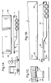
- Fig. 1A shows schematically a conventional arrangement of truck 1, trailer 2 and container 3 in a case where the container is fastened to the chassis by respective twist-locks 7 below each of the corner fittings 4B at the four bottom corners of the container. Similar corner fittings 4T are provided at the four top corners of the container 3.
- the truck 1 has a fifth wheel 5 in which a kingpin 6 of the trailer 2 is received in a conventional manner.
- the arrangement shown in Fig. 1A is conventional.
- Figs. 1B and 1C show a modified version of the arrangement of Fig. 1A in which corresponding parts are designated by the same reference numerals.
- the trailer 2 is of the so-called gooseneck skeletal form having a rear portion 2A and a front portion 2B of reduced height.
- the height of the container 3 on the trailer is reduced by lowering the rear portion 2A of the trailer and providing a recess 3A at the front of the container within which the front portion 2B of the trailer is received (the front portion 2B of the trailer being at the same height as in Fig. 1).
- a bar 8 extends across the full width of the trailer.
- the bar 8 is immediately in front of the front end of the container 3 when the container is properly placed on the trailer.
- a pair of securing pins 9 are mounted at respective ends of the bar 8 and are positioned so that they can be secured into openings 10 (Fig. 1C) in the front faces of the corner fittings 4B of the container.
- the container 3 is secured by twist-locks 7 as in the case of the arrangement of Fig. 1A.
- Fig. 2 shows a modification to the arrangement shown in Figs. 1B and 1C to provide an arrangement embodying the invention.
- the bar 8 and securing pins 10 are replaced by a locking device, part of which is shown in Fig. 2.
- the locking device comprises a central bar 8 on each end of which a mounting member 11 is fixed, each mounting member serving to mount a carrier member 12 and securing pin 13 for pivotal movement as will be described in more detail below.
- Fig. 2 shows the bar 8 and the mounting member 11, carrier member 12 and pin 13 that are at the right hand end (as seen in Fig. 2) of the bar; a similar mounting member 11, carrier member 12 and pin 13 are provided at the opposite end (left hand end as seen in Fig. 2) of the bar.
- the bar 8 is shown in more detail in Figs. 3A to 3C. It will be seen that the bar is of rectangular tubular construction and carries at its right hand end (as seen in Fig. 3A) a locking pin mechanism 14 including a manually operable lever 15 and a locking pin 16 which is moveable by operation of the lever 15 from a locking position in which the pin 16 projects through the tubular wall of the bar 8 into the interior of the bar and an unlocked position in which the pin 16 is clear of the interior of the bar.
- Such locking pin mechanisms are known per se and the particular mechanism chosen is not significant to the present invention and will not be described further. It will be understood that another locking pin mechanism 14 (not shown) is provided at the left hand end (as seen in Fig. 3A) of the bar 8.
- the mounting member 11 provided at the right hand end (as seen is Fig. 2) of the bar 8 is shown in Figs. 4A to 4C.
- the mounting member 11 is a composite member composed principally of three parts: a tubular member 17 which is dimensioned to fit inside the bar 8; a smaller tubular member 18 one end of which fits inside the member 17 and the other end of which projects from the member 17; and a leaf spring 19, one end 19A of which is fixed to the tubular member 18 and the other end 19B of which projects outwardly from the tubular member.
- the tubular member 17 carries around its exterior surface a total of six slide strips 20 which serve to mount the tubular member 17 slidably in the bar 8.
- the tubular member 17 has a pair of holes (not shown) in its side wall 22 for engagement by the locking pin 16; thus the member 17 can be secured in the bar 8 in the position shown in Fig. 2 or in a position which in this particular example is 84 mm further out (that is with the member 17 further to the right as seen in Fig. 2).
- the tubular member 18 is fixed to the member 17 and has two vertical through bores 23, 24 in the part of the member 18 that projects out from the member 17.
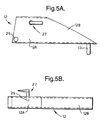
- the carrier member 12 is shown in Figs. 5A and 5B and is of tubular construction. It is dimensioned to fit over the outwardly projecting part of the member 18. As seen in Fig. 5A an inner portion 12A of the carrier member is of constant width but an outer portion 12B steadily reduces in width to a pointed distal end at which the securing pin 13 is provided.
- the carrier member 12 has a through bore 25 which, when the carrier member is fitted over the member 18, becomes aligned with the through bore 23 in the member 18.
- a pivot shaft 26 (Fig. 2) passes through the bores 23 and 25 and mounts the carrier member 12 for pivotal movement about a vertical axis on the mounting member.
- the carrier member 12 also has a locking pin mechanism 27 similar to the mechanism 14 on the bar 8 and including a locking pin 29 movable by operation of a lever 28 of the mechanism from a locking position in which the pin 29 protrudes into the interior of the carrier member and an unlocked position in which the pin is clear of the interior of the carrier member.
- the pin 29 can be moved into a locking position only if the pin 29 is aligned with the through bore 24 in the member 18. That alignment occurs when the carrier member and member 18 are oriented as shown in Figs. 4A and 5A. If the pin 29 is retracted by operation of the lever 28, it then becomes possible to pivot the carrier member in an anticlockwise direction (as seen in Figs. 2 and 5A) through an angle, which in this particular example is 9.3°, to a position in which an end face of the carrier member 12 abuts an end face of the bar 8; this position of the carrier member is shown in Fig. 2.
- the leaf spring 19 extends through the interior of the carrier member 12 and the distal tip of the spring is adjacent to the interior side wall of the carrier member in the position shown in Fig. 2.
- the carrier member 12 is pivoted from that position, however, to one in which the locking pin 29 is engageable in the bore 24, the carrier member bears against the spring 19 and bends it.
- the carrier member is resiliently biased away from the position where the locking pin 29 is aligned with the bore 24, towards the position shown in Fig. 2.
- the operation of the locking device will now be described, principally with reference to Fig. 2, starting from a situation in which the locking device is in the position shown in Fig. 2 with a container being loaded onto the trailer chassis.
- the container 3 is placed on the chassis with the bottom of the front end of the container immediately adjacent to the bar 8, as previously described for the known arrangement of Figs. 1B and 1C.
- the container 3 is a 45 foot (13716 mm) container and has corner fittings 4B of an unconventional kind: as seen in Fig. 2, the corner fitting 4B has a front end face which has an inner portion 41 aligned with the front face of the container and an inclined outer portion 42.
- a corner fitting of this kind is described in further detail in International Patent Application No. PCT/GB97/03070.
- the corner fitting 4B is hollow and has an opening 43 in its face portion 41.
- the carrier member 12 is pivoted manually clockwise (as seen in Fig. 2) against the resilient bias of the leaf spring 19 so that the securing pin 13 enters the opening 43 in the corner fitting 4B of the container 3.
- the locking pin 29 becomes aligned with the bore 24 and the user can operate the lever 28 to cause the locking pin to enter the bore 24, thereby locking the carrier member in the position in which the pin 13 fully engages the corner fitting 4B.
- Fig. 2 when viewed in a direction transverse to the longitudinal axis of the locking device and transverse to the longitudinal axis of the pin 29 (i.e.
- the distal end of the carrier member when viewed in the direction of Fig. 2) the distal end of the carrier member is thin, when measured along the longitudinal axis of the pin; therefore, the locking device is positioned substantially entirely inside a vertical plane containing the inclined face portion 42. That is of significance in ensuring that the combination of the container and the locking device complies with European regulations. Such regulations require that no part of the locking device (or any other part of the front end of the trailer) extends more than 2040 mm from the vertical axis of pivoting, that axis being the longitudinal axis of the kingpin 6.
- a user To release the securing pin 13 from the corner fitting, a user simply operates the lever 28 to retract the locking pin 29. The carrier member is then free to pivot back, under the bias of the leaf spring 19, to the position shown in Fig. 2, in which the container is no longer secured and can be lifted off the trailer.
Landscapes
- Engineering & Computer Science (AREA)
- Transportation (AREA)
- Mechanical Engineering (AREA)
- Lock And Its Accessories (AREA)
- Fittings On The Vehicle Exterior For Carrying Loads, And Devices For Holding Or Mounting Articles (AREA)
- Body Structure For Vehicles (AREA)
Priority Applications (1)
| Application Number | Priority Date | Filing Date | Title |
|---|---|---|---|
| DE29924303U DE29924303U1 (de) | 1998-06-19 | 1999-06-15 | Verriegelungsvorrichtung für Frachtcontainer |
Applications Claiming Priority (2)
| Application Number | Priority Date | Filing Date | Title |
|---|---|---|---|
| GB9813325 | 1998-06-19 | ||
| GB9813325A GB2338742B (en) | 1998-06-19 | 1998-06-19 | A locking device for a freight container |
Publications (4)
| Publication Number | Publication Date |
|---|---|
| EP0965485A2 true EP0965485A2 (de) | 1999-12-22 |
| EP0965485A3 EP0965485A3 (de) | 2003-04-16 |
| EP0965485B1 EP0965485B1 (de) | 2009-07-29 |
| EP0965485B8 EP0965485B8 (de) | 2009-09-09 |
Family
ID=10834091
Family Applications (1)
| Application Number | Title | Priority Date | Filing Date |
|---|---|---|---|
| EP99304644A Expired - Lifetime EP0965485B8 (de) | 1998-06-19 | 1999-06-15 | Verriegelungsvorrichtung für Frachtcontainer |
Country Status (4)
| Country | Link |
|---|---|
| EP (1) | EP0965485B8 (de) |
| AT (1) | ATE437774T1 (de) |
| DE (1) | DE69941171D1 (de) |
| GB (1) | GB2338742B (de) |
Citations (3)
| Publication number | Priority date | Publication date | Assignee | Title |
|---|---|---|---|---|
| US3614153A (en) | 1969-06-02 | 1971-10-19 | Fruehauf Corp | Universal trailer chassis |
| US4486132A (en) | 1980-10-11 | 1984-12-04 | Gerd Schulz | Device for front end locking of containers |
| BE1002515A3 (nl) | 1989-06-16 | 1991-03-05 | Renders | Containerchassis. |
Family Cites Families (6)
| Publication number | Priority date | Publication date | Assignee | Title |
|---|---|---|---|---|
| GB1135142A (en) * | 1967-01-24 | 1968-11-27 | Seaway Containers Ltd | Improvements in articulated trailers |
| US4352517A (en) * | 1980-11-10 | 1982-10-05 | Bertolini William A | Front locking pin for gooseneck container chassis |
| US4496187A (en) * | 1982-12-28 | 1985-01-29 | Pontecorvo John J | Trailer construction |
| JPS63502745A (ja) * | 1986-02-21 | 1988-10-13 | ティ−シ−エス・コンテナ−ズ・プロプライアタリ−・リミテッド | 貨物用コンテナ |
| GB8804263D0 (en) * | 1988-02-24 | 1988-03-23 | Blair George Plc | Front locking pin assembly for locking container to trailer &c |
| US5575599A (en) * | 1994-04-15 | 1996-11-19 | Penz Products, Inc. | Container lock pin system |
-
1998
- 1998-06-19 GB GB9813325A patent/GB2338742B/en not_active Expired - Fee Related
-
1999
- 1999-06-15 DE DE69941171T patent/DE69941171D1/de not_active Expired - Lifetime
- 1999-06-15 EP EP99304644A patent/EP0965485B8/de not_active Expired - Lifetime
- 1999-06-15 AT AT99304644T patent/ATE437774T1/de not_active IP Right Cessation
Patent Citations (3)
| Publication number | Priority date | Publication date | Assignee | Title |
|---|---|---|---|---|
| US3614153A (en) | 1969-06-02 | 1971-10-19 | Fruehauf Corp | Universal trailer chassis |
| US4486132A (en) | 1980-10-11 | 1984-12-04 | Gerd Schulz | Device for front end locking of containers |
| BE1002515A3 (nl) | 1989-06-16 | 1991-03-05 | Renders | Containerchassis. |
Also Published As
| Publication number | Publication date |
|---|---|
| GB9813325D0 (en) | 1998-08-19 |
| EP0965485A3 (de) | 2003-04-16 |
| DE69941171D1 (de) | 2009-09-10 |
| GB2338742A (en) | 1999-12-29 |
| EP0965485B1 (de) | 2009-07-29 |
| GB2338742B (en) | 2002-11-20 |
| ATE437774T1 (de) | 2009-08-15 |
| EP0965485B8 (de) | 2009-09-09 |
Similar Documents
| Publication | Publication Date | Title |
|---|---|---|
| CA1284118C (en) | Interlocking adapter casting | |
| CA1224224A (en) | Extensible chassis for shipping container | |
| US3984117A (en) | Locking device for freight carts | |
| US4708683A (en) | Toy car carrier | |
| US4561671A (en) | Extensible chassis for hauling containers | |
| US6309153B1 (en) | Intermodal transfer trailer | |
| US4266820A (en) | Variance compensating coupler for container-carrying trailer chassis | |
| CA2166757C (en) | Container support pedestal | |
| US5785472A (en) | Convertible support for a header transport wagon | |
| US5236342A (en) | Universally mounted hand truck holder apparatus and method | |
| US7883305B2 (en) | Removable twistlock | |
| EP0340937B1 (de) | Vorrichtung zum Anbringen einer Hebeeinrichtung an einen Container oder dergl. | |
| EP0965485B1 (de) | Verriegelungsvorrichtung für Frachtcontainer | |
| US3682423A (en) | Retractable twist lock | |
| US3866970A (en) | Twist lock container support | |
| GB2298856A (en) | On-vehicle storage of an adaptor for a load handling system | |
| US4743150A (en) | Elevatable hitch assembly with lateral slot for trailer on flatcar | |
| US4400121A (en) | Railway car hitch for a trailer | |
| US20100226740A1 (en) | Shipping container handling | |
| US5186598A (en) | Retractable arm loading/unloading device and vehicle comprising same | |
| US6109641A (en) | First-in/first-out tractor and semi-trailer cargo transfer system | |
| EP1028881B1 (de) | Sattelkupplungsanordnung für ein auf gleisen verfahrbares fahrzeug | |
| AU2008207602B2 (en) | Method and apparatus for loading containers | |
| CN211174073U (zh) | 一种固压橇装置 | |
| EP0679566B1 (de) | Vorrichtung zum Verhindern des Nickschwingens von Rad-Schiene-Sattelschleppern während des Schienentransportes |
Legal Events
| Date | Code | Title | Description |
|---|---|---|---|
| PUAI | Public reference made under article 153(3) epc to a published international application that has entered the european phase |
Free format text: ORIGINAL CODE: 0009012 |
|
| AK | Designated contracting states |
Kind code of ref document: A2 Designated state(s): AT BE CH CY DE DK ES FI FR GB GR IE IT LI LU MC NL PT SE |
|
| AX | Request for extension of the european patent |
Free format text: AL;LT;LV;MK;RO;SI |
|
| PUAL | Search report despatched |
Free format text: ORIGINAL CODE: 0009013 |
|
| AK | Designated contracting states |
Designated state(s): AT BE CH CY DE DK ES FI FR GB GR IE IT LI LU MC NL PT SE |
|
| AX | Request for extension of the european patent |
Extension state: AL LT LV MK RO SI |
|
| RIC1 | Information provided on ipc code assigned before grant |
Ipc: 7B 60P 1/64 B Ipc: 7B 60P 7/13 A |
|
| 17P | Request for examination filed |
Effective date: 20031009 |
|
| AKX | Designation fees paid |
Designated state(s): AT BE CH CY DE DK ES FI FR GB GR IE IT LI LU MC NL PT SE |
|
| 17Q | First examination report despatched |
Effective date: 20040204 |
|
| RAP1 | Party data changed (applicant data changed or rights of an application transferred) |
Owner name: GEEST NEDERLAND B.V. |
|
| 17Q | First examination report despatched |
Effective date: 20040204 |
|
| GRAP | Despatch of communication of intention to grant a patent |
Free format text: ORIGINAL CODE: EPIDOSNIGR1 |
|
| GRAS | Grant fee paid |
Free format text: ORIGINAL CODE: EPIDOSNIGR3 |
|
| GRAA | (expected) grant |
Free format text: ORIGINAL CODE: 0009210 |
|
| AK | Designated contracting states |
Kind code of ref document: B1 Designated state(s): AT BE CH CY DE DK ES FI FR GB GR IE IT LI LU MC NL PT SE |
|
| REG | Reference to a national code |
Ref country code: GB Ref legal event code: FG4D |
|
| REG | Reference to a national code |
Ref country code: CH Ref legal event code: EP |
|
| RBV | Designated contracting states (corrected) |
Designated state(s): AT BE CH CY DE DK ES FI FR GR IE IT LI LU MC NL PT SE |
|
| REG | Reference to a national code |
Ref country code: IE Ref legal event code: FG4D |
|
| REF | Corresponds to: |
Ref document number: 69941171 Country of ref document: DE Date of ref document: 20090910 Kind code of ref document: P |
|
| PG25 | Lapsed in a contracting state [announced via postgrant information from national office to epo] |
Ref country code: SE Free format text: LAPSE BECAUSE OF FAILURE TO SUBMIT A TRANSLATION OF THE DESCRIPTION OR TO PAY THE FEE WITHIN THE PRESCRIBED TIME-LIMIT Effective date: 20090729 Ref country code: FI Free format text: LAPSE BECAUSE OF FAILURE TO SUBMIT A TRANSLATION OF THE DESCRIPTION OR TO PAY THE FEE WITHIN THE PRESCRIBED TIME-LIMIT Effective date: 20090729 Ref country code: ES Free format text: LAPSE BECAUSE OF FAILURE TO SUBMIT A TRANSLATION OF THE DESCRIPTION OR TO PAY THE FEE WITHIN THE PRESCRIBED TIME-LIMIT Effective date: 20091109 Ref country code: AT Free format text: LAPSE BECAUSE OF FAILURE TO SUBMIT A TRANSLATION OF THE DESCRIPTION OR TO PAY THE FEE WITHIN THE PRESCRIBED TIME-LIMIT Effective date: 20090729 |
|
| PG25 | Lapsed in a contracting state [announced via postgrant information from national office to epo] |
Ref country code: PT Free format text: LAPSE BECAUSE OF FAILURE TO SUBMIT A TRANSLATION OF THE DESCRIPTION OR TO PAY THE FEE WITHIN THE PRESCRIBED TIME-LIMIT Effective date: 20091129 |
|
| PG25 | Lapsed in a contracting state [announced via postgrant information from national office to epo] |
Ref country code: DK Free format text: LAPSE BECAUSE OF FAILURE TO SUBMIT A TRANSLATION OF THE DESCRIPTION OR TO PAY THE FEE WITHIN THE PRESCRIBED TIME-LIMIT Effective date: 20090729 |
|
| PG25 | Lapsed in a contracting state [announced via postgrant information from national office to epo] |
Ref country code: BE Free format text: LAPSE BECAUSE OF FAILURE TO SUBMIT A TRANSLATION OF THE DESCRIPTION OR TO PAY THE FEE WITHIN THE PRESCRIBED TIME-LIMIT Effective date: 20090729 |
|
| PLBE | No opposition filed within time limit |
Free format text: ORIGINAL CODE: 0009261 |
|
| STAA | Information on the status of an ep patent application or granted ep patent |
Free format text: STATUS: NO OPPOSITION FILED WITHIN TIME LIMIT |
|
| 26N | No opposition filed |
Effective date: 20100503 |
|
| PG25 | Lapsed in a contracting state [announced via postgrant information from national office to epo] |
Ref country code: GR Free format text: LAPSE BECAUSE OF FAILURE TO SUBMIT A TRANSLATION OF THE DESCRIPTION OR TO PAY THE FEE WITHIN THE PRESCRIBED TIME-LIMIT Effective date: 20091030 |
|
| PGFP | Annual fee paid to national office [announced via postgrant information from national office to epo] |
Ref country code: DE Payment date: 20100610 Year of fee payment: 12 |
|
| PG25 | Lapsed in a contracting state [announced via postgrant information from national office to epo] |
Ref country code: MC Free format text: LAPSE BECAUSE OF NON-PAYMENT OF DUE FEES Effective date: 20100630 |
|
| REG | Reference to a national code |
Ref country code: CH Ref legal event code: PL |
|
| REG | Reference to a national code |
Ref country code: FR Ref legal event code: ST Effective date: 20110228 |
|
| PG25 | Lapsed in a contracting state [announced via postgrant information from national office to epo] |
Ref country code: IT Free format text: LAPSE BECAUSE OF FAILURE TO SUBMIT A TRANSLATION OF THE DESCRIPTION OR TO PAY THE FEE WITHIN THE PRESCRIBED TIME-LIMIT Effective date: 20090729 |
|
| PG25 | Lapsed in a contracting state [announced via postgrant information from national office to epo] |
Ref country code: LI Free format text: LAPSE BECAUSE OF NON-PAYMENT OF DUE FEES Effective date: 20100630 Ref country code: CH Free format text: LAPSE BECAUSE OF NON-PAYMENT OF DUE FEES Effective date: 20100630 Ref country code: IE Free format text: LAPSE BECAUSE OF NON-PAYMENT OF DUE FEES Effective date: 20100615 |
|
| PG25 | Lapsed in a contracting state [announced via postgrant information from national office to epo] |
Ref country code: FR Free format text: LAPSE BECAUSE OF NON-PAYMENT OF DUE FEES Effective date: 20100630 |
|
| REG | Reference to a national code |
Ref country code: DE Ref legal event code: R119 Ref document number: 69941171 Country of ref document: DE Effective date: 20120103 |
|
| PG25 | Lapsed in a contracting state [announced via postgrant information from national office to epo] |
Ref country code: DE Free format text: LAPSE BECAUSE OF NON-PAYMENT OF DUE FEES Effective date: 20120103 |
|
| PG25 | Lapsed in a contracting state [announced via postgrant information from national office to epo] |
Ref country code: CY Free format text: LAPSE BECAUSE OF FAILURE TO SUBMIT A TRANSLATION OF THE DESCRIPTION OR TO PAY THE FEE WITHIN THE PRESCRIBED TIME-LIMIT Effective date: 20090729 |
|
| PG25 | Lapsed in a contracting state [announced via postgrant information from national office to epo] |
Ref country code: LU Free format text: LAPSE BECAUSE OF NON-PAYMENT OF DUE FEES Effective date: 20100615 |
|
| PGFP | Annual fee paid to national office [announced via postgrant information from national office to epo] |
Ref country code: NL Payment date: 20170614 Year of fee payment: 19 |
|
| REG | Reference to a national code |
Ref country code: NL Ref legal event code: MM Effective date: 20180701 |
|
| PG25 | Lapsed in a contracting state [announced via postgrant information from national office to epo] |
Ref country code: NL Free format text: LAPSE BECAUSE OF NON-PAYMENT OF DUE FEES Effective date: 20180701 |