EP0965486A2 - Dispositif pour monter un appareil d'éclairage sur un véhicule - Google Patents
Dispositif pour monter un appareil d'éclairage sur un véhicule Download PDFInfo
- Publication number
- EP0965486A2 EP0965486A2 EP99102986A EP99102986A EP0965486A2 EP 0965486 A2 EP0965486 A2 EP 0965486A2 EP 99102986 A EP99102986 A EP 99102986A EP 99102986 A EP99102986 A EP 99102986A EP 0965486 A2 EP0965486 A2 EP 0965486A2
- Authority
- EP
- European Patent Office
- Prior art keywords
- lighting device
- locking element
- locking
- vehicle part
- fork
- Prior art date
- Legal status (The legal status is an assumption and is not a legal conclusion. Google has not performed a legal analysis and makes no representation as to the accuracy of the status listed.)
- Withdrawn
Links
Images
Classifications
-
- B—PERFORMING OPERATIONS; TRANSPORTING
- B60—VEHICLES IN GENERAL
- B60Q—ARRANGEMENT OF SIGNALLING OR LIGHTING DEVICES, THE MOUNTING OR SUPPORTING THEREOF OR CIRCUITS THEREFOR, FOR VEHICLES IN GENERAL
- B60Q1/00—Arrangement of optical signalling or lighting devices, the mounting or supporting thereof or circuits therefor
- B60Q1/02—Arrangement of optical signalling or lighting devices, the mounting or supporting thereof or circuits therefor the devices being primarily intended to illuminate the way ahead or to illuminate other areas of way or environments
- B60Q1/04—Arrangement of optical signalling or lighting devices, the mounting or supporting thereof or circuits therefor the devices being primarily intended to illuminate the way ahead or to illuminate other areas of way or environments the devices being headlights
- B60Q1/0408—Arrangement of optical signalling or lighting devices, the mounting or supporting thereof or circuits therefor the devices being primarily intended to illuminate the way ahead or to illuminate other areas of way or environments the devices being headlights built into the vehicle body, e.g. details concerning the mounting of the headlamps on the vehicle body
- B60Q1/0441—Arrangement of optical signalling or lighting devices, the mounting or supporting thereof or circuits therefor the devices being primarily intended to illuminate the way ahead or to illuminate other areas of way or environments the devices being headlights built into the vehicle body, e.g. details concerning the mounting of the headlamps on the vehicle body the housing being fastened onto the vehicle body using means other than screws
Definitions
- the invention relates to a device for fastening a lighting device on a vehicle part according to the Genus of claim 1.
- Such a device is described in DE 195 19 651 A1 known.
- This device has a on the vehicle part arranged holding element.
- At the Lighting device is a locking element between an unlocked position and one Locked position movably arranged.
- the Lighting device is in a mounting direction with the Locking element in its unlocked position on Vehicle part attachable.
- Locking element in its locking position movable, this on the holding element of the vehicle part locked so that the lighting device on Vehicle part is held.
- a disadvantage of this known Device is that the locking element itself directly must be accessible to this on the holding element of the To lock or unlock the vehicle part, which at cramped installation conditions of the lighting device is not always possible, so that the arrangement of the Holding element is difficult.
- the inventive device for attaching a Lighting device on a vehicle part with the Features according to claim 1 has the advantage that the locking element for locking and unlocking it on Holding element does not need to be directly accessible because its movement between its unlocked position and its locking position by means of the actuating element can be done.
- the arrangement of the actuating element can taking into account the respective installation conditions be chosen so that it is sufficiently accessible is. There is only a small amount for its rotary actuation Installation space required.
- the features according to claim 2 enable a simple deflection device for conversion the rotational movement of the actuating element in the longitudinal movement of the locking element.
- the features according to claim 3 enable a compensation of the rotation of the Actuator occurring movement perpendicular to Longitudinal direction of movement of the locking element.
- Through the Features according to claim 5 is a safe management of Locking element reached.
- In claim 6 is one simple design of the locking element to the Lock indicated on the holding element.
- the training according to Claim 8 allows easy and safe installation of the Lighting device.
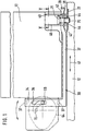
- FIG. 1 shows a simplified representation one by means of a device on a vehicle part attached lighting device in a view in Arrow direction I in Figure 3,
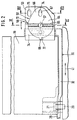
- Figure 2 the Illumination device in sections in a view in Arrow direction II in Figure 3
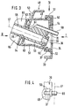
- Figure 3 the Lighting device in a cross section along line III-III in Figure 2
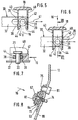
- Figure 4 the lighting device excerpts in a view in the direction of arrow IV in Figure 3,
- Figure 5 the lighting device in one Longitudinal section along line V-V in Figure 1 with a Locking element in an unlocked position
- Figure 6 the lighting device in longitudinal section along line V-V with the locking element in one Locked position
- Figure 7 the lighting device excerpts in a cross section along line VII-VII in Figure 6 and Figure 8, the lighting device in one Cross section along line VIII-VIII in Figure 2.
- a lighting device 10 is shown in FIGS. 1 to 8 shown, which can be attached to a vehicle part 12.
- the lighting device 10 can be a headlight, a Lamp or a headlight-lamp unit and this is intended in particular for motor vehicles.
- the Vehicle part 12 can be a body part or a other front part of the vehicle.
- the vehicle part 12 has a receptacle for the lighting device 10, in which the lighting device 10 in a mounting direction 16 5 to 7 can be introduced.
- the Mounting direction 16 of the lighting device 10 can for example from the front of the vehicle against the direction of travel and roughly parallel to one Longitudinal axis of the vehicle.
- the lighting device 10 may have a housing 18 in which one or more Reflectors and these assigned one or more Light sources can be arranged, but in the Figures are not shown.
- a pin 20 which is approximately vertical or inclined and at least approximately perpendicular to Mounting direction 16 of the lighting device 10 extends.
- the pin 20 can be made of plastic or metal and can be formed in one piece with the vehicle part 12 or connected as a separate part to the vehicle part 12 be.
- the pin 20 with an approximately horizontal wall 22 of the Vehicle part 12 connected, for example on his one End pressed into this or screwed to it.
- On the free end of the pin 20 has a head 21 enlarged cross section.
- the Illumination device 10 On the outside of the housing 18 the Illumination device 10 is a locking element 30 arranged.
- this Locking element 30 as in Figures 1 and 2 shown one on the underside of the housing 18 almost the entire width of the housing 18 extending rod-like section 32, which has a flat, for example, has approximately rectangular cross-section, wherein the section 32 is arranged such that its larger Extent is approximately horizontal.
- the Section 32 is for this below the housing 18 Lighting device 10 only a small overall height needed.
- At one end of section 32 of the Locking element 30 closes in one piece with this an approximately perpendicular to this upward Section 34.
- the locking element 30 thus the shape of a lying L on.
- Section 34 is one running in the direction of its longitudinal extent elongated opening 36 formed.
- At the top and bottom of section 34 is as shown in Figure 3 each molded from this protruding L-shaped hook 37. The free end of the upper hook 37 runs down and that free end of the lower hook 37 extends upwards.
- Section 32 of the locking element 30 is as in FIGS Figures 5 and 6 shown forked.
- the Forks 38, 39 run at least approximately parallel to Longitudinal extension of section 32 and in mounting direction 16 at a distance from each other.
- the further in assembly direction 16 arranged fork 38 is shorter than that other fork 39.
- Section 32 of the Locking element 30 can be forked End area as shown in Figures 1 and 2 Have offset, so that the forked end portion of the Section 32 runs somewhat higher than the rest of the area of section 32.
- the locking element 30 is made preferably made of plastic and is made by injection molding made in one piece.
- the housing 18 of the lighting device 10 instructs its back in the area where the fork-shaped End of the locking element 30 is arranged as in the Figures 5 and 6 shown two of these at a distance in Direction of the longitudinal extent of section 32 of the Locking element 30 mutually projecting walls 40 on.
- the walls 40 have near their lower ends each have a slot-like opening 42 through which the fork-shaped end of the locking element 30 passes through. Near their lower ends, in the area in the openings 42 are formed, the walls 40 each have a thickening 44 directed towards one another, so that there the distance between the walls 40 is reduced is.
- the thickenings 44 taper in the direction of assembly 16 towards the ends of the walls 40 and the thickenings 44 are close to the 16 opposite to mounting direction, on Housing 18 molded ends of the walls 44 together connected, the opening between the walls 44 there runs out in a U-shape.
- the forked end of the Locking element 30 passes through with little play Openings 42 of the walls 40 on the housing 18, so that the locking element 30 in the direction of the longitudinal axis 41 the openings 42 is slidably guided.
- the Longitudinal direction of movement of the locking element 30 is parallel to the longitudinal axis 41.
- section 34 of locking element 30 stands a bracket from the housing 18 as shown in Figure 3 48, which has an upper wall 49, on the one after pointing above, at least approximately parallel to the longitudinal axis 41 of the openings 42 and thus in the longitudinal direction of movement of the Locking element 30 extending bar 50 is formed is.
- the console 48 also has a lower wall 51 on the one facing downwards in the same way Bar 52 is formed.
- the hook 37 of section 34 overlap the bars 50 and 52, respectively, so that the Locking element 30 via its along the strips 50 or 52 slidable hooks 37 slidably guided is.
- the console 48 also has two at a distance mutually arranged end walls 53, 54 on the each have an opening 55, 56, the Openings 55, 56 are arranged coaxially to one another.
- the Opening 56 in the section 34 of the locking element 30 adjacent end wall 54 has a smaller one Diameter on than the opening 55 of the other end wall 53.
- a Actuator 58 rotatably mounted about the axis 57, the from the side facing away from section 34 into the Openings 55,56 is introduced.
- the actuator 58 has a pin 59 which extends through the openings 55, 56 is inserted, the pin 59 at its front end has a smaller diameter and there in a Opening 56 of section 34 of locking element 30 Bearing bush 60 surrounding adjacent end wall 54 is stored.
- the one lying between the end walls 53, 54 Section of the pin 59 has one or more Thickenings 61 on, whereby the diameter of the pin 59th there is slightly larger than the diameter of the opening 55.
- the opening 55 is somewhat expandable resiliently what for example through one or more of the opening 55 surrounding openings 63 of the end wall 53 can be achieved can.
- the actuating element 58 also has one integrally formed on the pin 59 head 64, the compared to the pin 59 a much larger Has a cross section and that on the end wall 54 opposite side of the end wall 53 is arranged. Of the The head 64 of the actuating element 58 has two, for example at a distance from one another transversely running webs 65 on which to manually twist the Actuator 58 can be attacked.
- the head 64 of the actuating element 58 can essentially round one Have cross section, however, a peripheral region has cam-shaped projection 66.
- the projection 66 has one formed in the radial direction as an elongated hole 67 Opening up.
- the head 64 also stands in the radial direction a nose 68 protrudes.
- the actuator 58 is in Figure 3 shown in its unlocked position.
- the end wall 54 has next to the opening 56 an opening 70, which is approximately as a section of a Axis of rotation 57 coaxial circular arc is formed and by which the finger 69 protrudes through.
- the breakthrough 70 runs above and to the side of the opening 56 of the end wall 54 to the housing 18.
- the finger 69 reaches into the opening 36 of section 34 of locking element 30.
- the Opening 55 in the end wall 53 has a side Extension for the passage of finger 69 on.
- the Actuator 58 is preferably made of plastic and is made in one piece by injection molding.
- the end wall 53 of the console 48 of the housing 18 has how shown in FIG. 1 on its end wall 54 opposite side two with respect to the axis of rotation 57 of the Actuator 58 at approximately an angle of 90 ° projections 72 spaced apart from one another.
- the end wall 53 also points on this side as in FIG. 3 shown a surrounding the opening 55 at a distance Collar 73 on which the head 64 of the actuating element 58 sits in the direction of the axis of rotation 57.
- End wall 53 is laterally next to the opening 55 approximately in same radial distance from the axis of rotation 57 one in opening 74 formed in the radial direction as an elongated hole present like the elongated hole 67 in the projection 66 of the head 64 of the actuating element 58.
- the elongated hole 74 is approximately in horizontal direction to the side of the opening 55 arranged. Another is above the elongated hole 74 Elongated hole in the end wall 53 is also available runs approximately horizontally.
- the actuating element 58 is on the housing 18 Lighting device 18 mounted by its pin 59th inserted through the opening 55 of the end wall 53 with the finger 69 through the cross-sectional expansion the opening 55 can pass through.
- the end of the pin 59 passes through the opening 56 of the end wall 54 and into the bearing bush 60.
- the finger 69 passes through the Breakthrough 70 through.
- the locking element 30 is mounted on the housing 18, by its forked end in the openings 42 of the Walls 40 of the housing 18 is inserted.
- the two Hook 37 of the locking element 30 are on the Last mounted 50.52 and the finger 69 of the Actuator 58 is inserted into the opening 36 of the section 34 of the locking element 30 inserted.
- the Locking element 30 is then on the housing 18 in its Longitudinal direction of movement 41 in the openings 42 and at the Last 50,52 slidably guided.
- the locking element 30 is between an unlocked position, that is one left end position as shown in Figure 1, and a locking position, this is a right end position as shown in Figure 1, displaceable.
- a Displacement of the locking element 30 between it Unlocking position and its locking position in the longitudinal direction of movement 41 is by a rotation of the Actuator 58 allows about its axis of rotation 57 via the in the opening 36 of the locking element 30th engaging finger 69 in the longitudinal movement of the Locking element 30 is converted.
- the one Rotation of the actuator 58 occurring movement of the finger 69 in the vertical direction is indicated by the as Elongated opening 36 balanced in the Finger 69 is freely movable in the vertical direction.
- the nose 68 of the head 64 In the position of the actuator 58 corresponding to the Unlocking position of the locking element 30 is located the nose 68 of the head 64 according to FIG Clockwise in contact with the right projection 72 of the End wall 53 and in the position of the actuating element 58 corresponding to the locking position of the Locking element 30 is the nose 68 of whose head 64 counterclockwise in plant on left projection 72 of end wall 53.
- the locking element 30 is in its Unlocked position shown in the longer Fork 39 protrudes between the walls 40 which shorter forks 38, however, not between walls 40 protrudes so that between the walls 40 in the range of whose thickenings 44 remain an opening.
- the in arranged in its unlocked position according to FIG Locking element 30 becomes lighting device 10 in the direction of arrow 16 into the receptacle of the vehicle part 12 inserted.
- the pin 20 arranged on the vehicle part 12 can with little play in the opening between the Walls 40 occur in the area of their thickenings 44 and the lighting device 10 can so in the mounting direction 16 be inserted far until the pin 20 on the edge of Opening between the walls 40 or on the fork tine 39 comes to the plant.
- the walls 40 with the thickenings 44 thus form a receptacle for the pin 20 in this can be introduced.
- the end wall 53 of the console 50 of the Housing 18 of the lighting device 10 comes in the End position of the housing 18 in the mounting direction 16 as in FIG. 8 shown on a wall 80 of the vehicle part 12 for Investment.
- On the wall 80 is approximately parallel to Mounting direction 16 extending bolt 81 arranged in the slot 75 of the end wall 53 occurs, whereby the Lighting device 10 is centered on the vehicle part 12 and is also provisional.
- Actuating element 58 according to Figure 2 against Twisted clockwise until its nose 68 on the left Projection 72 of the end wall 53 comes to rest.
- the locking element 30 in its Locked position shown in Figure 5, so that also whose short fork 38 occurs between the walls 40 and engages behind the pin 20. So that is Lighting device 10 fixed to the pin 20, the cross to the mounting direction 16 in an approximately horizontal direction little play in the opening between the walls 40 in Area of their thickenings 44 is fixed and in and against mounting direction 16 by the encompassing Forks 38,39 of the locking element 30 is fixed. It can be provided that the housing 18 of the Lighting device 10 on the wall 22 of the Vehicle part 12 is seated, the head 21 of the pin 20th above the area of the walls 40 with the thickenings 44 is arranged so that the housing 18 also in the direction the longitudinal axis of the pin 20 is fixed between the Wall 22 and the head 21 of the pin 20th
- the locking position of the locking element 30 as shown in Figure 2 is the nose 68 on the left Projection 72 of the end wall 53 and the slot 67 of the Formation 66 of the head 64 of the actuating element 58 is aligned with the elongated hole 74 of the end wall 53 arranged.
- the wall 80 of the vehicle part 12 faces as in FIG 2 and 8 shown in the area of the elongated holes 67 and 74 an opening 81, with the elongated holes 67 and 74 a fastening element 82 in the form of a screw, which is screwed into the opening 81 or one like a detent 81 clips can be fixed in the opening.
- the Fastening element 82 becomes the actuating element 58 in its the locking position of the locking element 30 corresponding rotary position blocked so that this cannot be twisted unintentionally.
- Lighting device 10 overall on vehicle part 12 fixed.
- one or more additional attachment points are provided be on which these by means of known fasteners such as screws with the vehicle part 12 is connected.
- the two described above Attachment points through the pin 20 and that this attacking locking element 30 and the means of the fastener 82 fixed bracket 48 is formed are at the bottom of the lighting device 10 arranged.
- the at least one other attachment point is preferably at an upper portion of the Lighting device 10 are arranged.
Landscapes
- Engineering & Computer Science (AREA)
- Mechanical Engineering (AREA)
- Lighting Device Outwards From Vehicle And Optical Signal (AREA)
- Fastening Of Light Sources Or Lamp Holders (AREA)
Applications Claiming Priority (2)
| Application Number | Priority Date | Filing Date | Title |
|---|---|---|---|
| DE29810988U DE29810988U1 (de) | 1998-06-19 | 1998-06-19 | Vorrichtung zur Befestigung einer Beleuchtungseinrichtung an einem Fahrzeugteil |
| DE29810988U | 1998-06-19 |
Publications (2)
| Publication Number | Publication Date |
|---|---|
| EP0965486A2 true EP0965486A2 (fr) | 1999-12-22 |
| EP0965486A3 EP0965486A3 (fr) | 2002-01-16 |
Family
ID=8058770
Family Applications (1)
| Application Number | Title | Priority Date | Filing Date |
|---|---|---|---|
| EP99102986A Withdrawn EP0965486A3 (fr) | 1998-06-19 | 1999-02-15 | Dispositif pour monter un appareil d'éclairage sur un véhicule |
Country Status (4)
| Country | Link |
|---|---|
| US (1) | US6199817B1 (fr) |
| EP (1) | EP0965486A3 (fr) |
| JP (1) | JP3064947U (fr) |
| DE (1) | DE29810988U1 (fr) |
Families Citing this family (4)
| Publication number | Priority date | Publication date | Assignee | Title |
|---|---|---|---|---|
| EP1544032B1 (fr) * | 2003-12-15 | 2010-02-10 | Compagnie Plastic Omnium | Support de bloc optique pour véhicule automobile, bloc optique, ensemble d'une face avant technique et d'un tel support et/ou d'un bloc optique |
| FR2883237B1 (fr) * | 2005-03-15 | 2007-05-11 | Valeo Vision Sa | Systeme de fixation d'un projecteur sur un bouclier de vehicule routier et procede d'installation et de fixation du projecteur sur le bouclier |
| DE102005037816A1 (de) | 2005-08-08 | 2007-02-22 | Hbpo Gmbh | Vorrichtung zur justierbaren Befestigung eines Scheinwerfers |
| GB2512892A (en) * | 2013-04-10 | 2014-10-15 | Ford Global Tech Llc | A method and apparatus for attaching a driver airbag module to a steering wheel |
Citations (1)
| Publication number | Priority date | Publication date | Assignee | Title |
|---|---|---|---|---|
| DE19519651A1 (de) | 1995-05-30 | 1996-12-05 | Bosch Gmbh Robert | Scheinwerfer für Fahrzeuge |
Family Cites Families (9)
| Publication number | Priority date | Publication date | Assignee | Title |
|---|---|---|---|---|
| JPS58183327A (ja) * | 1982-04-19 | 1983-10-26 | Nissan Motor Co Ltd | リトラクタブルヘツドランプのストツパ機構 |
| DE3305169C1 (de) * | 1983-02-15 | 1984-07-26 | Audi Nsu Auto Union Ag, 7107 Neckarsulm | Kraftfahrzeug mit durch Klappen abdeckbaren Scheinwerfern |
| DE3442042C2 (de) * | 1983-11-16 | 1986-11-13 | General Motors Corp., Detroit, Mich. | Verdeckter Scheinwerfer für Kraftfahrzeuge |
| US4747023A (en) * | 1987-07-14 | 1988-05-24 | General Motors Corporation | Vehicle headlamp assembly |
| DE19507585C2 (de) * | 1995-03-04 | 2002-04-18 | Bosch Gmbh Robert | Scheinwerfer-Leuchten-Einheit für Fahrzeuge |
| DE19519655B4 (de) * | 1995-05-30 | 2010-04-08 | Automotive Lighting Reutlingen Gmbh | An einem Frontteil eines Fahrzeugs angeordnete Beleuchtungseinrichtung |
| JP3193604B2 (ja) * | 1995-12-25 | 2001-07-30 | 株式会社小糸製作所 | 放電バルブを有する車両用灯具 |
| FR2753147B1 (fr) * | 1996-09-06 | 1998-12-04 | Valeo Vision | Feu pour vehicule automobile, pour montage depuis l'exterieur |
| DE19741605B4 (de) * | 1996-09-27 | 2006-06-29 | Volkswagen Ag | Befestigungsvorrichtung für einen Scheinwerfer an einem Kraftfahrzeug |
-
1998
- 1998-06-19 DE DE29810988U patent/DE29810988U1/de not_active Expired - Lifetime
-
1999
- 1999-02-15 EP EP99102986A patent/EP0965486A3/fr not_active Withdrawn
- 1999-04-22 US US09/296,732 patent/US6199817B1/en not_active Expired - Fee Related
- 1999-06-16 JP JP1999004372U patent/JP3064947U/ja not_active Expired - Lifetime
Patent Citations (1)
| Publication number | Priority date | Publication date | Assignee | Title |
|---|---|---|---|---|
| DE19519651A1 (de) | 1995-05-30 | 1996-12-05 | Bosch Gmbh Robert | Scheinwerfer für Fahrzeuge |
Also Published As
| Publication number | Publication date |
|---|---|
| JP3064947U (ja) | 2000-01-28 |
| US6199817B1 (en) | 2001-03-13 |
| DE29810988U1 (de) | 1999-10-28 |
| EP0965486A3 (fr) | 2002-01-16 |
Similar Documents
| Publication | Publication Date | Title |
|---|---|---|
| DE102008033303B4 (de) | Verriegelungsvorrichtung für einen Fahrzeugsitz | |
| DE10132883C2 (de) | Armaturenbrettanordnung für Kraftfahrzeuge | |
| DE69412439T2 (de) | Spangenfassung | |
| EP2133495A2 (fr) | Serrure de véhicule automobile | |
| DE2939722A1 (de) | Verstelleinrichtung fuer schiebefenster | |
| DE10144166C5 (de) | Schloss für eine Kraftfahrzeugtür | |
| DE3823502A1 (de) | Kraftfahrzeug-tuerverschlussvorrichtung | |
| DE10217488B4 (de) | Vorrichtung zum Betätigen eines Verschlusses von Türen, Klappen od.dgl., insbesondere an Fahrzeugen | |
| EP1158128A2 (fr) | Plaque de montage pour la fixation d'un bras de charnière d'une charnière de meuble | |
| DE102008018738B4 (de) | Fahrzeugseitige Kupplungsbaugruppe einer Anhängerkupplung | |
| EP1070641A2 (fr) | Dispositif de réglage en hauteur de la ceinture de sécurité d'un véhicule | |
| DE2554106A1 (de) | Fuehrungshalter fuer elektronische baugruppen | |
| EP0893306B1 (fr) | Agencement de coffre destiné à être monté dans des véhicules automobiles, en particulier pour être aménagé dans le dossier du siège d'un tel véhicule | |
| DE29810988U1 (de) | Vorrichtung zur Befestigung einer Beleuchtungseinrichtung an einem Fahrzeugteil | |
| DE2144756C3 (de) | Fernbetätigungsvorrichtung, insbesondere für Kraftfahrzeugtürschlösser | |
| DE3026441A1 (de) | Verstelleinrichtung fuer schiebefenster | |
| DE3804176A1 (de) | Tuerverschluss fuer hausgeraete o. dgl. | |
| DE19840642C2 (de) | Befestigungselement für einen Betätigungszug | |
| EP0728885B1 (fr) | Unité de poignée pour une portière | |
| DE69503584T2 (de) | Geräteträger anzubringen auf einer Einbaudose und Befestigungsteil zum Gebrauch mit solchem Geräteträger | |
| EP1103676B1 (fr) | Crémone-serrure | |
| DE3702118A1 (de) | Motorhaube fuer ein kraftfahrzeug | |
| DE3340449A1 (de) | Scheibenwischer, insbesondere fuer kraftfahrzeuge | |
| DE102007052605B3 (de) | Gleiter für ein Schiebedach, Schiebeelement und Schiebedachsystem | |
| DE19605967A1 (de) | Scheinwerfer-Leuchten-Einheit für Fahrzeuge |
Legal Events
| Date | Code | Title | Description |
|---|---|---|---|
| PUAI | Public reference made under article 153(3) epc to a published international application that has entered the european phase |
Free format text: ORIGINAL CODE: 0009012 |
|
| AK | Designated contracting states |
Kind code of ref document: A2 Designated state(s): AT BE CH CY DE DK ES FI FR GB GR IE IT LI LU MC NL PT SE Kind code of ref document: A2 Designated state(s): DE FR |
|
| AX | Request for extension of the european patent |
Free format text: AL;LT;LV;MK;RO;SI |
|
| PUAL | Search report despatched |
Free format text: ORIGINAL CODE: 0009013 |
|
| AK | Designated contracting states |
Kind code of ref document: A3 Designated state(s): AT BE CH CY DE DK ES FI FR GB GR IE IT LI LU MC NL PT SE |
|
| AX | Request for extension of the european patent |
Free format text: AL;LT;LV;MK;RO;SI |
|
| 17P | Request for examination filed |
Effective date: 20020214 |
|
| AKX | Designation fees paid |
Free format text: DE FR |
|
| RAP1 | Party data changed (applicant data changed or rights of an application transferred) |
Owner name: AUTOMOTIVE LIGHTING REUTLINGEN GMBH |
|
| STAA | Information on the status of an ep patent application or granted ep patent |
Free format text: STATUS: THE APPLICATION IS DEEMED TO BE WITHDRAWN |
|
| 18D | Application deemed to be withdrawn |
Effective date: 20060901 |