EP0965557A2 - Auslegerpositionierung mit hydraulischem Einstellzylinder - Google Patents
Auslegerpositionierung mit hydraulischem Einstellzylinder Download PDFInfo
- Publication number
- EP0965557A2 EP0965557A2 EP99111059A EP99111059A EP0965557A2 EP 0965557 A2 EP0965557 A2 EP 0965557A2 EP 99111059 A EP99111059 A EP 99111059A EP 99111059 A EP99111059 A EP 99111059A EP 0965557 A2 EP0965557 A2 EP 0965557A2
- Authority
- EP
- European Patent Office
- Prior art keywords
- tube
- actuator
- piston
- chamber
- telescopic
- Prior art date
- Legal status (The legal status is an assumption and is not a legal conclusion. Google has not performed a legal analysis and makes no representation as to the accuracy of the status listed.)
- Withdrawn
Links
- 239000012530 fluid Substances 0.000 claims abstract description 22
- 238000000034 method Methods 0.000 claims abstract 2
- 239000004519 grease Substances 0.000 claims description 7
- 238000007789 sealing Methods 0.000 claims description 3
- 238000013022 venting Methods 0.000 claims description 3
- 230000000712 assembly Effects 0.000 claims 4
- 238000000429 assembly Methods 0.000 claims 4
- 238000012986 modification Methods 0.000 description 3
- 230000004048 modification Effects 0.000 description 3
- 239000000945 filler Substances 0.000 description 2
- 230000002411 adverse Effects 0.000 description 1
- 230000000694 effects Effects 0.000 description 1
- 238000009434 installation Methods 0.000 description 1
- 230000003313 weakening effect Effects 0.000 description 1
Images

Classifications
-
- B—PERFORMING OPERATIONS; TRANSPORTING
- B66—HOISTING; LIFTING; HAULING
- B66C—CRANES; LOAD-ENGAGING ELEMENTS OR DEVICES FOR CRANES, CAPSTANS, WINCHES, OR TACKLES
- B66C23/00—Cranes comprising essentially a beam, boom, or triangular structure acting as a cantilever and mounted for translatory of swinging movements in vertical or horizontal planes or a combination of such movements, e.g. jib-cranes, derricks, tower cranes
- B66C23/62—Constructional features or details
- B66C23/64—Jibs
- B66C23/70—Jibs constructed of sections adapted to be assembled to form jibs or various lengths
- B66C23/701—Jibs constructed of sections adapted to be assembled to form jibs or various lengths telescopic
- B66C23/708—Jibs constructed of sections adapted to be assembled to form jibs or various lengths telescopic locking devices for telescopic jibs
-
- B—PERFORMING OPERATIONS; TRANSPORTING
- B66—HOISTING; LIFTING; HAULING
- B66C—CRANES; LOAD-ENGAGING ELEMENTS OR DEVICES FOR CRANES, CAPSTANS, WINCHES, OR TACKLES
- B66C23/00—Cranes comprising essentially a beam, boom, or triangular structure acting as a cantilever and mounted for translatory of swinging movements in vertical or horizontal planes or a combination of such movements, e.g. jib-cranes, derricks, tower cranes
- B66C23/62—Constructional features or details
- B66C23/64—Jibs
- B66C23/70—Jibs constructed of sections adapted to be assembled to form jibs or various lengths
- B66C23/701—Jibs constructed of sections adapted to be assembled to form jibs or various lengths telescopic
- B66C23/707—Jibs constructed of sections adapted to be assembled to form jibs or various lengths telescopic guiding devices for telescopic jibs
Definitions
- the present invention relates to a means for laterally guiding or fixing the angular position of two telescopic parts relative to each other. More specifically, the present invention relates to a hydraulic guidance actuator assembly for a crane jib.
- Telescopic parts are provided with a fixing means so that during installation, or less frequently also when repair is needed, an extensible telescopic part can be set relative to the supporting telescopic part guiding the extensible telescopic part, for example, by a clasping action.
- These fixing means need to be designed in part so that they act perpendicular to the main direction of deformation of the telescopic parts, i.e., in the horizontal plane for example, in the case of a horizontally located telescopic jib (crane jib in the down condition), perpendicularly loaded downwards. This means that the location of a telescopic part can be maintained in this horizontal plane by the fixing means to achieve optimum alignment of two telescopic parts relative to each other.
- horizontal'' and vertical'' as orientation indications used in this context relate to the down condition of a jib consisting of telescopic parts, i.e. oriented horizontally substantially parallel to the ground.
- Conventional fixing means for telescopic parts having substantially rectangular cross-sections comprise in the lower cross-sectional area of an inner telescopic part stoppers applied to both sides which are also termed guide plates.
- an adjuster applied to the outer telescopic part consists of a lockable setscrew, the face surface area of which, when screwed in, comes into contact with the main surface area of the stopper.
- the contact surface area between the setscrew and guide plate runs parallel to the vertical, main direction of deformation, so that also in loaded operation of the jib it can be assured that contact is made with this surface area, thus defining the position.
- the setscrew is screwed into a setscrew hub provided in the outer telescopic part until the setscrew is in snug contact with the guide plate at its face surface area. Since it is accessible on the outside of the outer telescopic part such a fixing means offers greatly facilitated handling.
- jib profiles have become popular comprising lower rounded shell sections which are usually curved outwards, thus causing major problems in continuing to use the conventional system for a fixing means, as described above, in the region of lower, curved telescopic part shells.
- the adjuster of the fixing means comprising a piston/cylinder unit arranged on the inner telescopic parts which may be actuated by fluid supply/discharge.
- the adjuster including the shiftable element is relocated from the outer telescopic part to the inner telescopic part where a mounting can be made advantageously, which is not supported predominantly directly by the lower shell. It is advantageously made possible in accordance with the invention to mount a horizontally shiftable element of the adjuster so that problems regarding the steady-state loading capacity of the lower shell are avoided.
- the passage for the shiftable element is included in the inner telescopic part at a location in the footing thereof where the loading moment is less, thus making for a design advantage as compared to conventional fixing means in which the passage (setscrew hub) was located in the stem portion of the outer telescopic part.
- the abutment surface area is located between the stopper and the shiftable element in the main direction of deformation of the telescopic parts parallel to the vertical, longitudinal center plane of the later.
- Both the shiftable element and the stopper thus have abutment surface areas extending vertically, as a result of which it is again assured that in loaded operation these abutment surface areas are in contact at all times, as a result of which relative fixing is also assured in the case of curved lower shells.
- the shiftable element in accordance with the invention is horizontally shiftable and the stopper comprises at least one surface area section located parallel to a front face surface area of the shiftable element.
- the piston of the piston/cylinder unit is the component that serves as the shiftable element, the piston/cylinder unit itself then comprising a pressurizing space located in the direction of the telescopic part interior, which may be filled more particularly with hydraulic fluid or grease and featuring an outer connection which is accessible from without through openings in the telescopic parts in the operating position of the fixing means.
- such a pressurizing space is readily accessible at its outer connection when minor openings are provided in the telescopic parts where they do not detriment the steady-state loading capacity, i.e. where the piston is located at the stopper when the openings overlap.
- Gaining access to the outer connection of the pressurizing space via the openings is now greatly facilitated by means of a hydraulic hose or a pressurized grease hose so that fixing can be undertaken from without by simple ways and means.
- a vehicular arrangement in accordance with the invention for two telescopic parts of a crane jib, more particularly for a vehicular crane comprises two fixing means as described above, arranged in the lower portion of the telescopic parts, positioned substantially in a mirror-inverse arrangement relative to the vertically longitudinal center plane of the jib.
- this fixing arrangement may comprise fixing means in accordance with the invention which are arranged on the lower telescopic sections configured curved or oriented inclined to the longitudinal center plane.
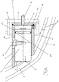
- FIG. 1 illustrates an outer telescopic part 12 and an inner telescopic part 13 each of which comprise in the lower portion shell-shaped segments curved outwards.
- the fixing means 10 is provided, with which the angular position of the telescopic parts 12 and 13 can be maintained relative to each other
- another fixing means 10 is likewise provided on the opposite side, this fixing means not being visible, however, in this half-section.
- Fig. 1 serves to make the location of the fixing means 10 clear in the arrangement as a whole, it being more particularly evident that the mounting element 16 for fixing means 10 is supported primarily by a vertically oriented beam 17, i.e. without requiring any fasteners which would substantially reduce the steady-stare loading capacity to be provided in the shells themselves.
- the substantial parts of the guiding device, namely the stopper 9, the piston 2 and the cylinder 1 are evident from Fig. 1; their functioning and arrangement being depicted more precisely from Fig. 2.
- Fig. 2 illustrates the region of the fixing means 10 on a magnified scale, again illustrating the outer and inner telescopic shells 12 and 13.
- the stopper 9 Secured to the curved outer telescopic shell 12 on the inside is the stopper 9.
- This stopper 9 comprises a surface area section 8, which in the fixing action abuts the front face surface area 7 of the piston.
- the contact surface area of the surface areas 7 and 8 are oriented parallel to the vertically longitudinal center plane V (see Fig. 1) so that it is assured at all times that these surface areas come into contact even when the jib is operated under load.
- the piston 2 is movably located in the cylinder 1.
- the cylinder 1 On the right-hand side the cylinder 1 comprises the cylinder bottom 3 which is held in place in the mount 16 by means of a fastener bolt 5, the mount in turn, as evident from Fig. 1, being securely mounted at an inner longitudinal strut 17 of the inner telescopic part 13.
- the pressurizing space in accessible from without through a filter port 14 which in the condition as shown is dosed off by a sealing ring with the screw plug 15.
- the pressurizing space 18 is filled with fluid, i.e., for example, hydraulic fluid or grease, the piston is unable to shift horizontally in this condition, thus retaining the fixed position of the telescopic parts 12 and 13.
- a screw 11 provided as a torsion lock which can be likewise screwed into place with a specific clearance once the piston position has been fixed. Via a vent passage 20 the screw hole may also be used as a means of venting the pressurizing space 18, this being the reason why the screw 11 is sealed in its mount by means of a sealing ring (not shown).
- the screw plug 15 When the telescopic parts 12 and 13 are positioned relative to each other the screw plug 15 needs to be removed to permit flow of a pressurizing fluid (hydraulic fluid or grease) into the pressurizing space 18 or to drain it therefrom.
- a pressurizing fluid hydroaulic fluid or grease
- the filler port 14 is accessible via two openings 20, 20' in the telescopic parts.
- the pressurizing space 18 becomes de-pressurized, alter which, for example, a grease pump can be secured to the filler port through the openings 20, 20' and sealed so that by means of a hose pressurized fluid can be pumped into the pressurizing space 18 initially until the face surface area 7 comes into snug contact with the surface area section 8 of the telescopic part 12.
- the screw plug 15 After having removed the pressurized fluid connection the screw plug 15 can then be returned in place, thus locking the fixed position.
- the invention thus provides a means of precisely and infinitely setting telescopic parts having curved lower shell parts from without with facilitated access, having no drawback as regards the steady-state loading capacity.
Landscapes
- Engineering & Computer Science (AREA)
- Mechanical Engineering (AREA)
- Jib Cranes (AREA)
- Actuator (AREA)
Applications Claiming Priority (2)
| Application Number | Priority Date | Filing Date | Title |
|---|---|---|---|
| DE19826924A DE19826924A1 (de) | 1998-06-17 | 1998-06-17 | Auslegerfixierung mit Einstellzylinder |
| DE19826924 | 1998-06-17 |
Publications (2)
| Publication Number | Publication Date |
|---|---|
| EP0965557A2 true EP0965557A2 (de) | 1999-12-22 |
| EP0965557A3 EP0965557A3 (de) | 2000-09-27 |
Family
ID=7871124
Family Applications (1)
| Application Number | Title | Priority Date | Filing Date |
|---|---|---|---|
| EP99111059A Withdrawn EP0965557A3 (de) | 1998-06-17 | 1999-06-15 | Auslegerpositionierung mit hydraulischem Einstellzylinder |
Country Status (5)
| Country | Link |
|---|---|
| US (1) | US6164468A (de) |
| EP (1) | EP0965557A3 (de) |
| JP (1) | JP2000159482A (de) |
| CA (1) | CA2275014A1 (de) |
| DE (1) | DE19826924A1 (de) |
Families Citing this family (10)
| Publication number | Priority date | Publication date | Assignee | Title |
|---|---|---|---|---|
| EP1072554B1 (de) * | 1999-07-30 | 2004-03-17 | Liebherr-Werk Ehingen GmbH | Kran mit einem Teleskopausleger |
| DE10048224B4 (de) * | 2000-09-21 | 2005-06-02 | Terex-Demag Gmbh & Co. Kg | Verriegelungseinheit für einen Teleskopausleger eines Krans |
| US6499612B1 (en) | 2001-07-27 | 2002-12-31 | Link-Belt Construction Equipment Co., L.P., Lllp | Telescoping boom assembly with rounded profile sections and interchangeable wear pads |
| US7322484B2 (en) * | 2001-08-24 | 2008-01-29 | Redmond Gary Australia Pty. Ltd. | Moisture shedding system |
| US6601719B2 (en) | 2001-09-21 | 2003-08-05 | Link-Belt Construction Equipment Co., L.P., Lllp | Locking and latching system for a telescoping boom |
| DE102009009944B4 (de) * | 2009-02-20 | 2011-02-24 | Terex-Demag Gmbh | Sicherungs- und Verbolzungseinheit |
| DE202010014103U1 (de) * | 2010-10-08 | 2012-01-10 | Liebherr-Werk Ehingen Gmbh | Auslegerelement, Teleskopausleger sowie Baufahrzeug |
| WO2015176218A1 (zh) * | 2014-05-20 | 2015-11-26 | 徐州重型机械有限公司 | 单缸插销伸缩装置及起重机 |
| US10066363B1 (en) | 2017-07-13 | 2018-09-04 | Cnh Industrial America Llc | Wear pad system |
| IT201800020221A1 (it) * | 2018-12-19 | 2020-06-19 | Cifa Spa | Braccio telescopico per gru e gru comprendente tale braccio |
Citations (2)
| Publication number | Priority date | Publication date | Assignee | Title |
|---|---|---|---|---|
| US4264265A (en) * | 1979-05-25 | 1981-04-28 | J. I. Case Company | Adjusting slide mechanism for telescoping boom |
| JPH1017275A (ja) * | 1996-07-01 | 1998-01-20 | Aichi Corp | 伸縮ブームの摺動装置 |
Family Cites Families (15)
| Publication number | Priority date | Publication date | Assignee | Title |
|---|---|---|---|---|
| US3182409A (en) * | 1961-01-31 | 1965-05-11 | Freddy Leidgens | Shoe heel with a detachable wear lift |
| US3836011A (en) * | 1970-01-31 | 1974-09-17 | T Sakamoto | Extensible boom |
| US3782790A (en) * | 1972-04-03 | 1974-01-01 | Warner Swasey Co | Boom slider assembly |
| GB1437526A (en) * | 1972-10-09 | 1976-05-26 | Int Harvester Co | Extensible jib crane |
| US3830376A (en) * | 1973-02-16 | 1974-08-20 | Harnischfeger Corp | Telescopic jib and bearing means therefor |
| US3921819A (en) * | 1974-07-26 | 1975-11-25 | Kidde & Co Walter | Boom latch mechanism |
| US3931698A (en) * | 1974-11-20 | 1976-01-13 | The Warner & Swasey Company | Center guided crane boom |
| US4337601A (en) * | 1980-04-24 | 1982-07-06 | Harnischfeger Corporation | High-strength light-weight boom section for telescopic crane boom |
| FR2531691B1 (fr) * | 1982-08-10 | 1986-03-28 | Ppm Sa | Fleche telescopique a dispositifs d'appui et/ou de guidage de ses troncons perfectionnes |
| JPS60132898A (ja) * | 1983-05-24 | 1985-07-15 | 新明和工業株式会社 | 多段ブ−ムの案内装置 |
| JPS6013289A (ja) * | 1983-07-04 | 1985-01-23 | 株式会社日立製作所 | 原子炉燃料貯蔵設備 |
| SU1164202A1 (ru) * | 1983-11-28 | 1985-06-30 | Nikolaj V Dymov | Телескопическая стрела |
| FR2600384A1 (fr) * | 1986-06-19 | 1987-12-24 | Lamy Perret Paul | Dispositif de guidage pour un bras telescopique, notamment pour un manipulateur |
| DE4344795A1 (de) * | 1993-12-28 | 1995-06-29 | Liebherr Werk Ehingen | Fahrbarer Kran mit einem Teleskopausleger |
| JPH1017257A (ja) * | 1996-06-28 | 1998-01-20 | Hitachi Building Syst Co Ltd | 乗客コンベアの運転方向案内装置 |
-
1998
- 1998-06-17 DE DE19826924A patent/DE19826924A1/de not_active Ceased
-
1999
- 1999-06-15 EP EP99111059A patent/EP0965557A3/de not_active Withdrawn
- 1999-06-15 CA CA002275014A patent/CA2275014A1/en not_active Abandoned
- 1999-06-17 US US09/334,726 patent/US6164468A/en not_active Expired - Fee Related
- 1999-06-17 JP JP11170854A patent/JP2000159482A/ja active Pending
Patent Citations (2)
| Publication number | Priority date | Publication date | Assignee | Title |
|---|---|---|---|---|
| US4264265A (en) * | 1979-05-25 | 1981-04-28 | J. I. Case Company | Adjusting slide mechanism for telescoping boom |
| JPH1017275A (ja) * | 1996-07-01 | 1998-01-20 | Aichi Corp | 伸縮ブームの摺動装置 |
Non-Patent Citations (1)
| Title |
|---|
| PATENT ABSTRACTS OF JAPAN vol. 1998, no. 05 30 April 1998 (1998-04-30) * |
Also Published As
| Publication number | Publication date |
|---|---|
| JP2000159482A (ja) | 2000-06-13 |
| EP0965557A3 (de) | 2000-09-27 |
| US6164468A (en) | 2000-12-26 |
| CA2275014A1 (en) | 1999-12-17 |
| DE19826924A1 (de) | 1999-12-23 |
Similar Documents
| Publication | Publication Date | Title |
|---|---|---|
| US6164468A (en) | Jib positioning with hydraulic adjustment cylinder | |
| CN101392775B (zh) | 二级任意位置过盈锁紧套液压缸 | |
| US6409275B1 (en) | Frame attachment for vehicle | |
| US4442912A (en) | Tilt-cab truck including apparatus to secure uniform advance and retraction of the tilt cylinders | |
| US5307731A (en) | Housing system for hydraulic units | |
| US9797283B2 (en) | Method for mounting an oil sump and arrangement of an oil sump on an assembly formed by a crankcase and a flywheel housing | |
| CN100596323C (zh) | 支撑油缸及具有该支撑油缸的支撑装置、起重机 | |
| CN115959585A (zh) | 调平支腿油缸机构、调平支腿油缸液压单元和工程机械 | |
| CN115744687A (zh) | 调平支腿油缸机构、调平支腿油缸液压单元和工程机械 | |
| AU2021306716B2 (en) | Clevis-ended suspension strut manufactured without welds | |
| US7059292B2 (en) | Sealing structure for divided type cylinder block | |
| US4514983A (en) | Master cylinder attachment for plastic reservoir | |
| JPH08177809A (ja) | 油圧シリンダの昇降体のロック構造 | |
| KR20240151769A (ko) | 유압 시스템에 대한 연결부를 갖는 진동 댐퍼 | |
| JP6978717B1 (ja) | タンク一体型油圧ポンプ | |
| JPS6024649Y2 (ja) | ダンプカ−の荷箱傾動装置 | |
| US6000720A (en) | Tank mounting arrangement and method | |
| US4141423A (en) | Vehicle suspension apparatus | |
| EP1985859A2 (de) | Hydraulisches Pumpensystem mit integriertem Steuerschieber | |
| JP3047467U (ja) | 自動車用油圧ジャッキ | |
| KR910008007Y1 (ko) | 차량조립용 다용도 리프터 | |
| KR200247360Y1 (ko) | 차량정비용 리프트 | |
| KR200208187Y1 (ko) | 버스의 스페어 타이어 적재 구조 | |
| JP2005351314A (ja) | 油圧式エレベータの油圧シリンダ | |
| JP2551310Y2 (ja) | 立体駐車機のための油圧回路装置 |
Legal Events
| Date | Code | Title | Description |
|---|---|---|---|
| PUAI | Public reference made under article 153(3) epc to a published international application that has entered the european phase |
Free format text: ORIGINAL CODE: 0009012 |
|
| AK | Designated contracting states |
Kind code of ref document: A2 Designated state(s): DE ES FR GB IT |
|
| AX | Request for extension of the european patent |
Free format text: AL;LT;LV;MK;RO;SI |
|
| PUAL | Search report despatched |
Free format text: ORIGINAL CODE: 0009013 |
|
| AK | Designated contracting states |
Kind code of ref document: A3 Designated state(s): AT BE CH CY DE DK ES FI FR GB GR IE IT LI LU MC NL PT SE |
|
| AX | Request for extension of the european patent |
Free format text: AL;LT;LV;MK;RO;SI |
|
| RIC1 | Information provided on ipc code assigned before grant |
Free format text: 7B 66C 23/697 A |
|
| 17P | Request for examination filed |
Effective date: 20001030 |
|
| AKX | Designation fees paid |
Free format text: DE ES FR GB IT |
|
| 17Q | First examination report despatched |
Effective date: 20040317 |
|
| RTI1 | Title (correction) |
Free format text: TELESCOPIC JIB |
|
| STAA | Information on the status of an ep patent application or granted ep patent |
Free format text: STATUS: THE APPLICATION IS DEEMED TO BE WITHDRAWN |
|
| 18D | Application deemed to be withdrawn |
Effective date: 20051210 |