EP0965714A1 - Fixation d'une ferrure - Google Patents
Fixation d'une ferrure Download PDFInfo
- Publication number
- EP0965714A1 EP0965714A1 EP99111177A EP99111177A EP0965714A1 EP 0965714 A1 EP0965714 A1 EP 0965714A1 EP 99111177 A EP99111177 A EP 99111177A EP 99111177 A EP99111177 A EP 99111177A EP 0965714 A1 EP0965714 A1 EP 0965714A1
- Authority
- EP
- European Patent Office
- Prior art keywords
- fastening
- side wall
- profile
- fastening part
- frame
- Prior art date
- Legal status (The legal status is an assumption and is not a legal conclusion. Google has not performed a legal analysis and makes no representation as to the accuracy of the status listed.)
- Withdrawn
Links
Images

Classifications
-
- E—FIXED CONSTRUCTIONS
- E05—LOCKS; KEYS; WINDOW OR DOOR FITTINGS; SAFES
- E05D—HINGES OR SUSPENSION DEVICES FOR DOORS, WINDOWS OR WINGS
- E05D5/00—Construction of single parts, e.g. the parts for attachment
- E05D5/02—Parts for attachment, e.g. flaps
- E05D5/0215—Parts for attachment, e.g. flaps for attachment to profile members or the like
- E05D5/0223—Parts for attachment, e.g. flaps for attachment to profile members or the like with parts, e.g. screws, extending through the profile wall or engaging profile grooves
- E05D5/023—Parts for attachment, e.g. flaps for attachment to profile members or the like with parts, e.g. screws, extending through the profile wall or engaging profile grooves with parts extending through the profile wall
-
- E—FIXED CONSTRUCTIONS
- E05—LOCKS; KEYS; WINDOW OR DOOR FITTINGS; SAFES
- E05D—HINGES OR SUSPENSION DEVICES FOR DOORS, WINDOWS OR WINGS
- E05D5/00—Construction of single parts, e.g. the parts for attachment
- E05D5/02—Parts for attachment, e.g. flaps
- E05D5/0215—Parts for attachment, e.g. flaps for attachment to profile members or the like
- E05D5/0223—Parts for attachment, e.g. flaps for attachment to profile members or the like with parts, e.g. screws, extending through the profile wall or engaging profile grooves
- E05D5/0238—Parts for attachment, e.g. flaps for attachment to profile members or the like with parts, e.g. screws, extending through the profile wall or engaging profile grooves with parts engaging profile grooves
-
- E—FIXED CONSTRUCTIONS
- E05—LOCKS; KEYS; WINDOW OR DOOR FITTINGS; SAFES
- E05D—HINGES OR SUSPENSION DEVICES FOR DOORS, WINDOWS OR WINGS
- E05D7/00—Hinges or pivots of special construction
- E05D7/04—Hinges adjustable relative to the wing or the frame
- E05D7/0415—Hinges adjustable relative to the wing or the frame with adjusting drive means
- E05D7/0423—Screw-and-nut mechanisms
-
- E—FIXED CONSTRUCTIONS
- E05—LOCKS; KEYS; WINDOW OR DOOR FITTINGS; SAFES
- E05D—HINGES OR SUSPENSION DEVICES FOR DOORS, WINDOWS OR WINGS
- E05D7/00—Hinges or pivots of special construction
- E05D7/04—Hinges adjustable relative to the wing or the frame
- E05D2007/0461—Hinges adjustable relative to the wing or the frame in angular arrangement to the wing or the frame
-
- E—FIXED CONSTRUCTIONS
- E05—LOCKS; KEYS; WINDOW OR DOOR FITTINGS; SAFES
- E05D—HINGES OR SUSPENSION DEVICES FOR DOORS, WINDOWS OR WINGS
- E05D7/00—Hinges or pivots of special construction
- E05D7/04—Hinges adjustable relative to the wing or the frame
- E05D2007/0484—Hinges adjustable relative to the wing or the frame in a radial direction
-
- E—FIXED CONSTRUCTIONS
- E05—LOCKS; KEYS; WINDOW OR DOOR FITTINGS; SAFES
- E05Y—INDEXING SCHEME ASSOCIATED WITH SUBCLASSES E05D AND E05F, RELATING TO CONSTRUCTION ELEMENTS, ELECTRIC CONTROL, POWER SUPPLY, POWER SIGNAL OR TRANSMISSION, USER INTERFACES, MOUNTING OR COUPLING, DETAILS, ACCESSORIES, AUXILIARY OPERATIONS NOT OTHERWISE PROVIDED FOR, APPLICATION THEREOF
- E05Y2900/00—Application of doors, windows, wings or fittings thereof
- E05Y2900/10—Application of doors, windows, wings or fittings thereof for buildings or parts thereof
- E05Y2900/13—Type of wing
- E05Y2900/132—Doors
-
- E—FIXED CONSTRUCTIONS
- E05—LOCKS; KEYS; WINDOW OR DOOR FITTINGS; SAFES
- E05Y—INDEXING SCHEME ASSOCIATED WITH SUBCLASSES E05D AND E05F, RELATING TO CONSTRUCTION ELEMENTS, ELECTRIC CONTROL, POWER SUPPLY, POWER SIGNAL OR TRANSMISSION, USER INTERFACES, MOUNTING OR COUPLING, DETAILS, ACCESSORIES, AUXILIARY OPERATIONS NOT OTHERWISE PROVIDED FOR, APPLICATION THEREOF
- E05Y2900/00—Application of doors, windows, wings or fittings thereof
- E05Y2900/10—Application of doors, windows, wings or fittings thereof for buildings or parts thereof
- E05Y2900/13—Type of wing
- E05Y2900/148—Windows
Definitions
- the invention relates to an attachment of a Fitting part according to the preamble of claim 1 corresponding Art.
- the preferred example of a "fitting" is one to be attached to the fixed frame or sash frame Hinge part of a hinge for doors, windows and the like.
- the fixed one The frame and the sash frame consist of hollow profiles, being on each other with the wing closed opposite sides each have a C-shaped profile groove is provided to the outside, i.e. against each other framework is open.
- the fitting part belongs in this case into a hinge-like band, both of which Band parts with essentially flat, strip or tab-shaped Fasteners from the front of the frame located hinge pins in depth between the frame profiles to grab. Inside the respective C-shaped A groove-like clamping part is arranged in the profile groove.
- Screws clamp the strap parts and the associated parts Clamping parts against each other, so dag against each other directed edge lips of the C-shaped profile groove between the respective band part and the respective clamping part clamped and the tape this way on any Point is set in the longitudinal direction of the profile.
- the respective fastening part of a band part is in essentially flat, i.e. it has a dimension that is clear is less than the dimensions in the other two Dimesions.
- the area or "plane" of the fastener extends parallel to the hinge axis.
- the Fastening parts are screwed approximately in the middle the depth of the profile bars with their side walls connected. From this point, the fastening parts protrude free over a not insignificant distance from the gap between the respective fixed frame and the sash out in front and go in there the hinge part of the hinge part receiving the hinge pin about.
- a wing is made up of two superimposed Tapes stored.
- the invention is based, with fasteners the task the nature of this phenomenon in question counteract.
- the means for pivoting the fastener can comprise at least one screw according to claim 2, according to claim 3 to avoid additional space requirements can be designed as a grub screw.
- the fastening part is straight Formed tab and the screw about halfway up Depth of the profile bar arranged.
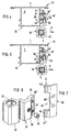
- Fig. 1 shows the front view of a door with a fixed frame 10 and a sash 20, the a heavy double glass pane 21 surrounds.
- the wing 20,21 is attached to the fixed frame by means of straps 30,30 arranged in the lower or upper area of the wing 20, 21 are pivotable about a vertical hinge axis stored. Due to the weight of the wing 20.21 "depends" this something, i.e. the horizontal width 22 of the gap 12 between fixed frame 10 and casement 20 is larger than the corresponding width 23 below. This comes about because the band parts of the one in the top Band 30 located under the weight of the Deform the wing a little.
- the fixed frame 10 consists of an extruded profile, designed as a hollow profile 1 made of an aluminum material.
- the profile bar 1 comprises a rectangular profile chamber 2, at the closed Wing opposite the sash 20 Side wall 3, the frame hinge part 15 of the band 30 attached is.
- the frame hinge part 15 comprises a hinge part 14 for receiving the hinge pin 10 and one of them approximately radially protruding fastening part 16 in the form of a straight one Tab of rectangular cross-section that extends through an attached directly next to the side wall 3 Opening 6 extends from the front into the interior 2 of the profile bar 1.
- the fastening part 16 goes almost over the entire depth of the profile bar 1 and is in the embodiment by two through the side wall 3 in the Fastening part 16 screws 48 on the Side wall 3 attached. In the sectional view of the Fig. 2 is only that behind the plane of the drawing Screw 48 visible.
- the load of the wing 20, 21 pulls on the upper band 30 the frame hinge part 15 according to FIG. 2 to the right in the sense of the arrow 5.
- the fastening part 16 of the band part 15 2 is still flat on the Inside of the side wall 3.
- the freely projecting front end can, however, carry loads of the fastening part 16, which is in the middle of the depth the profile bar 1 is held by the screw (s) 48, bend slightly in the direction of arrow 5, although the fastening part 16 at the opening delimiting supports front edge 11 of side wall 3, but this is bent to a certain extent.
- the effect is in any case, that the hinge pin 9 follows the load, shifted a little to the right and the gap 12 between fixed frame 10 and sash 20 in the manner shown in Fig. 1 gapes.
- the Screw 24 is also approximately in the middle of the depth of the Profile bar arranged, so about the same height as the fastening screws 48, and designed as a cap screw, whose head is in a corresponding cylindrical Recess of the fastening part 16 arranged and the Side wall 3 is facing.
- the screw 24 is completely below the right boundary surface the fastening part 16 disappeared; in the position 3 it is unscrewed somewhat, so that her head over the right boundary surface of the fastener 16 looks out and on the inside of the side wall 3 comes to the plant.
- Turn around screw 24 to be able is in the side wall 3 on the relevant Place an opening 25 provided.
- the principle is on a band part 15 relatively simple execution and attachment shown.
- the principle can also apply to other, more complex ones Band designs are used, as in FIG. 4 show to 7.
- profile bars 1 essentially those according to the 2 and 3, however, comprise on the outside of the eye wall 3 a C-shaped one that was molded during extrusion Profile groove 4.
- the C-shaped profile groove 4 has perpendicular to the longitudinal direction the profile bars 1 an oblong rectangular Cross section, the longer side of which extends into the depth of the Gap 12 between the fixed frame 10 and casement 20 extends.
- the web of the "C” or a longer side of the rectangular cross section are through the side wall 3 educated.
- the two legs of the "C” correspond to the shorter sides, angled at their outer ends by 90 ° are and lip lips 7,7 'that form each other are opposite and, when they touched, the other longer side of the rectangular section.
- the lip 7,7 'leave between them a continuous opening over the length of the profile bars 8 constant width by the facing each other End faces of the lip 7,7 'is limited.
- the Edge lips 7, 7 ' run parallel to the side wall 3 and have a constant, the side wall 3 approximately appropriate thickness.
- the band part 35 consists of a hinge part 37 with a recess 19 for the hinge pin and him receiving sockets and one of them approximately radially laterally protruding fastening part 36 (Fig. 6).
- the fastening part 36 engages with a kind of cranked Shoe 38, which differs from the hinge part 37 approximately in the longitudinal direction of the rectangular cross section of the profile groove 4 stretched from the front and outside into the interior of the Profile groove 4 and lies on its horizontally outer End 38 '' from the inside at the opposite lip 7 ' on.
- the fastening part 36 lies on the other edge lip 7 from the outside.
- the shoe fits" in the Profile groove 4, so that the fastening part 36 in the to Wall 3 parallel plane is largely fixed.
- a clamping part 40 acts with the fastening part 36 (Fig. 7) together, which e.g. made of flat material Steel can be punched, has about last shape and on a longitudinal edge facing the lip 7 to a thickness and the thickness of the clamping part 40 corresponding Stretch is cranked. With the outside 42 of the cranked edge 41 is the clamping part 40 in the assembled Condition on the inside of the lip 7 on the Inside on the outside of the lip 7 '.
- Both cooperating parts 36 and 40 are therefore once from the outside, the other from the inside to the respective edge lips 7,7 '.
- the two parts must thus intersect, as can be seen from FIGS. 4 and 5 is. So that this can be achieved with symmetrical application of force is the clamping part 40 at its cranked edge 41 provided with a U-shaped recess 45, which is shown in Fig. 7 and its length, in the longitudinal direction of the Profile bar 1 seen, the height of the fastening part 36 corresponds.
- the fastening part 36 can thus with the Shoe 38 inserted into the profile groove and then that Clamping part 40 are used, of which cranked Edge 41 of a remaining part 41 'above the Fastening part 36, the other remaining part 41 '' runs below the fastening part 36.
- the length of the Clamping part 40 two through holes 46 and over the Length of the shoe two threaded holes 47 aligned therewith distributed.
- Screws 48 are screwed into the bores 46, 47, by means of which the fastening part 36 and that Clamping part 40 pulled against each other in the axial direction of the screws 38 be, whereby the lip 7,7 'between the fastening part 36 and the clamping part 40 are clamped and this and thus the band part 35 in the longitudinal direction of the Profile bar 1 can be fixed non-positively.
- the dimensioning is taken so that when tightening the screws 48 there is no play at the lip 7,7 'and one the same is securely clamped.
- the attachment part 36 and the clamping part 40 on the lip 7,7 'alternately, i.e. each once from the inside and once from the outside.
- the attachment can therefore be made to one rectangular frame anywhere along the length of the supporting frame spar.
- the fastening part 36 of the band part 35 is approximately in Height of the screws 48, which in turn are approximately in the Middle of the depth of the profile bar 1 are located above the Edge lips 7,7 'of the profile groove 4 with the side wall 3 connected to the profile rod 1 and protrudes from this point freely forward to the area of the hinge pin 9 in front.
- the fastening part also has indentations that reduce its bending resistance.
- a grub screw Screw 54 may be provided, which is against the neighboring Area of the profile bar 1 sets and when screwing in a pivoting of the fastening part 36 or Band part 35 around a near the horizontally outer End 38 '' of the shoe 38 located vertical pivot axis in the Direction of arrow 5 'brings about, as it is already in Connection with FIGS. 2 and 3 is described.
- the mounting member 16 is inside the profile chamber 2, in Figs. 4 and 5 outside the same.
- the pivot point 11 is in the embodiment 2 and 3 located in the front area in which Embodiment of FIGS. 4 and 5 further back in Area of the end 38 '' of the shoe 38 there
- the lower hinge pin 9 is pivoted in the same Way as it shifts in the upper hinge pin through the Weight of the wing 20.21 happens, and in this way the gap parallelized.
- the screws 24, 54 are used for positioning of the band parts 15.35 reached when tightening the Screws 48 is retained. Support the screws 24.54 the band parts 15, 35 in the pivot position reached against the force of the screws used for fastening 48 on the side wall 3.
Landscapes
- Engineering & Computer Science (AREA)
- Mechanical Engineering (AREA)
- Clamps And Clips (AREA)
- Hinges (AREA)
Applications Claiming Priority (2)
| Application Number | Priority Date | Filing Date | Title |
|---|---|---|---|
| DE29811017U DE29811017U1 (de) | 1998-06-19 | 1998-06-19 | Befestigung eines Beschlagteils |
| DE29811017U | 1998-06-19 |
Publications (1)
| Publication Number | Publication Date |
|---|---|
| EP0965714A1 true EP0965714A1 (fr) | 1999-12-22 |
Family
ID=8058794
Family Applications (1)
| Application Number | Title | Priority Date | Filing Date |
|---|---|---|---|
| EP99111177A Withdrawn EP0965714A1 (fr) | 1998-06-19 | 1999-06-09 | Fixation d'une ferrure |
Country Status (2)
| Country | Link |
|---|---|
| EP (1) | EP0965714A1 (fr) |
| DE (1) | DE29811017U1 (fr) |
Cited By (5)
| Publication number | Priority date | Publication date | Assignee | Title |
|---|---|---|---|---|
| WO2004013440A1 (fr) * | 2002-07-26 | 2004-02-12 | Dr. Hahn Gmbh & Co. Kg | Penture pour portes, fenetres et objets similaires |
| EP1152112A3 (fr) * | 2000-05-02 | 2005-01-19 | Solarlux Aluminium Systeme Gmbh | Assemblage charnière-cadre ajustable |
| DE202005012153U1 (de) * | 2005-07-29 | 2006-12-14 | Dr. Hahn Gmbh & Co. Kg | Profil/Bandsystem |
| WO2014023537A1 (fr) * | 2012-08-08 | 2014-02-13 | Dr. Hahn Gmbh & Co. Kg | Structure de paumelle pour portes, fenêtres et analogues |
| EP2712989A1 (fr) * | 2012-09-26 | 2014-04-02 | Eldon Holding Aktiebolag | Charnière de porte réglable pour armoire électrique |
Citations (3)
| Publication number | Priority date | Publication date | Assignee | Title |
|---|---|---|---|---|
| US2744284A (en) * | 1952-04-12 | 1956-05-08 | Judson P Mcmillan | Adjustable door hinge |
| DE3015354A1 (de) | 1979-06-26 | 1981-01-29 | Ludwig Lindpointner | Scharnierbandverbindung fuer fenster, tueren und tore |
| US5072488A (en) * | 1990-03-14 | 1991-12-17 | Amweld Building Products, Inc. | Method and apparatus for mounting hinges to a door frame |
Family Cites Families (2)
| Publication number | Priority date | Publication date | Assignee | Title |
|---|---|---|---|---|
| DE7521278U (de) * | 1975-10-30 | Siegenia Frank Kg | Befestigungsvorrichtung für Beschlagteile an Metall- oder Kunststoffprofilen | |
| DE29500842U1 (de) * | 1995-01-20 | 1996-05-23 | Hewi Heinrich Wilke Gmbh, 34454 Arolsen | Einstellbares Scharnier für Türen, Fenster o.dgl. |
-
1998
- 1998-06-19 DE DE29811017U patent/DE29811017U1/de not_active Expired - Lifetime
-
1999
- 1999-06-09 EP EP99111177A patent/EP0965714A1/fr not_active Withdrawn
Patent Citations (3)
| Publication number | Priority date | Publication date | Assignee | Title |
|---|---|---|---|---|
| US2744284A (en) * | 1952-04-12 | 1956-05-08 | Judson P Mcmillan | Adjustable door hinge |
| DE3015354A1 (de) | 1979-06-26 | 1981-01-29 | Ludwig Lindpointner | Scharnierbandverbindung fuer fenster, tueren und tore |
| US5072488A (en) * | 1990-03-14 | 1991-12-17 | Amweld Building Products, Inc. | Method and apparatus for mounting hinges to a door frame |
Cited By (6)
| Publication number | Priority date | Publication date | Assignee | Title |
|---|---|---|---|---|
| EP1152112A3 (fr) * | 2000-05-02 | 2005-01-19 | Solarlux Aluminium Systeme Gmbh | Assemblage charnière-cadre ajustable |
| WO2004013440A1 (fr) * | 2002-07-26 | 2004-02-12 | Dr. Hahn Gmbh & Co. Kg | Penture pour portes, fenetres et objets similaires |
| DE202005012153U1 (de) * | 2005-07-29 | 2006-12-14 | Dr. Hahn Gmbh & Co. Kg | Profil/Bandsystem |
| WO2007014604A1 (fr) * | 2005-07-29 | 2007-02-08 | Hahn Gmbh & Co. Kg | Systeme a profile et a bande |
| WO2014023537A1 (fr) * | 2012-08-08 | 2014-02-13 | Dr. Hahn Gmbh & Co. Kg | Structure de paumelle pour portes, fenêtres et analogues |
| EP2712989A1 (fr) * | 2012-09-26 | 2014-04-02 | Eldon Holding Aktiebolag | Charnière de porte réglable pour armoire électrique |
Also Published As
| Publication number | Publication date |
|---|---|
| DE29811017U1 (de) | 1999-10-28 |
Similar Documents
| Publication | Publication Date | Title |
|---|---|---|
| DE69125572T2 (de) | Tragschiene für eine gläserne Tür oder Trennwand | |
| EP1238179A1 (fr) | Composant dote d'une penture et destine a des portes, des fenetres ou equivalent | |
| EP0995001B1 (fr) | Agencement d'une ferrure montee sur un cadre | |
| EP1231347B1 (fr) | Volet pour fenêtre avec au moins deux pentures | |
| EP0681081A1 (fr) | Fermeture pour ouvertures dans des parois de bâtiments ou similaires | |
| EP0539672B1 (fr) | Ferrure pour fixation dans une rainure d'un profilé rétréci des deux côtés | |
| EP0965714A1 (fr) | Fixation d'une ferrure | |
| DE19744832C2 (de) | Anordnung für den Einbau eines Fensterrahmens | |
| EP1441096B1 (fr) | Dispositif de fixation pour une ferrure | |
| EP3889384A1 (fr) | Profilé extrudé de section creuse de fenêtre ou de porte, système doté d'un tel profilé de section creuse et cadre fabriqué à partir de celui-ci | |
| EP1676970A2 (fr) | Fixation d'un élément de ferrure | |
| DE3631671C1 (en) | Fastening of a hinge strap to the frame of doors, windows and the like | |
| DE2516264A1 (de) | Befestigungsvorrichtung fuer beschlagteile an profilstaeben aus metall oder kunststoff | |
| DE9412472U1 (de) | Falt- oder Schwingflügeltor | |
| EP1659246A1 (fr) | Charnière pour volets | |
| EP0987396B1 (fr) | Habillage pour fenêtres ou portes | |
| DE19734647B4 (de) | Beschlagteil an einem Flügel oder einem festen Rahmen eines Fensters, einer Tür od. dgl. | |
| DE20221378U1 (de) | Befestigung eines Beschlagteils | |
| DE102005053650B3 (de) | Scharnierbeschlag | |
| DE9101597U1 (de) | Scharnier | |
| DE10341828B4 (de) | Hohlprofilrahmen für eine Insektenschutztür | |
| EP0752511A1 (fr) | Penture et fixation d'une penture | |
| EP1388627B1 (fr) | Dispositif de fixation pour une ferrure | |
| DE9206434U1 (de) | Band für Türen, Fenster u.dgl. | |
| DE2553801A1 (de) | Rahmenkonstruktion fuer tueren, fenster u.dgl. |
Legal Events
| Date | Code | Title | Description |
|---|---|---|---|
| PUAI | Public reference made under article 153(3) epc to a published international application that has entered the european phase |
Free format text: ORIGINAL CODE: 0009012 |
|
| AK | Designated contracting states |
Kind code of ref document: A1 Designated state(s): AT BE CH DE ES FR GB GR IT LI NL PT SE |
|
| AX | Request for extension of the european patent |
Free format text: AL;LT;LV;MK;RO;SI |
|
| 17P | Request for examination filed |
Effective date: 19991201 |
|
| AKX | Designation fees paid |
Free format text: AT BE CH DE ES FR GB GR IT LI NL PT SE |
|
| GRAG | Despatch of communication of intention to grant |
Free format text: ORIGINAL CODE: EPIDOS AGRA |
|
| 17Q | First examination report despatched |
Effective date: 20011213 |
|
| GRAG | Despatch of communication of intention to grant |
Free format text: ORIGINAL CODE: EPIDOS AGRA |
|
| GRAH | Despatch of communication of intention to grant a patent |
Free format text: ORIGINAL CODE: EPIDOS IGRA |
|
| STAA | Information on the status of an ep patent application or granted ep patent |
Free format text: STATUS: THE APPLICATION IS DEEMED TO BE WITHDRAWN |
|
| 18D | Application deemed to be withdrawn |
Effective date: 20020618 |