EP3889384A1 - Profilé extrudé de section creuse de fenêtre ou de porte, système doté d'un tel profilé de section creuse et cadre fabriqué à partir de celui-ci - Google Patents
Profilé extrudé de section creuse de fenêtre ou de porte, système doté d'un tel profilé de section creuse et cadre fabriqué à partir de celui-ci Download PDFInfo
- Publication number
- EP3889384A1 EP3889384A1 EP21163246.8A EP21163246A EP3889384A1 EP 3889384 A1 EP3889384 A1 EP 3889384A1 EP 21163246 A EP21163246 A EP 21163246A EP 3889384 A1 EP3889384 A1 EP 3889384A1
- Authority
- EP
- European Patent Office
- Prior art keywords
- channel
- hollow chamber
- chamber profile
- fastening
- longitudinal axis
- Prior art date
- Legal status (The legal status is an assumption and is not a legal conclusion. Google has not performed a legal analysis and makes no representation as to the accuracy of the status listed.)
- Granted
Links
Images


Classifications
-
- E—FIXED CONSTRUCTIONS
- E06—DOORS, WINDOWS, SHUTTERS, OR ROLLER BLINDS IN GENERAL; LADDERS
- E06B—FIXED OR MOVABLE CLOSURES FOR OPENINGS IN BUILDINGS, VEHICLES, FENCES OR LIKE ENCLOSURES IN GENERAL, e.g. DOORS, WINDOWS, BLINDS, GATES
- E06B3/00—Window sashes, door leaves, or like elements for closing wall or like openings; Layout of fixed or moving closures, e.g. windows in wall or like openings; Features of rigidly-mounted outer frames relating to the mounting of wing frames
- E06B3/04—Wing frames not characterised by the manner of movement
- E06B3/06—Single frames
- E06B3/08—Constructions depending on the use of specified materials
- E06B3/20—Constructions depending on the use of specified materials of plastics
- E06B3/22—Hollow frames
- E06B3/221—Hollow frames with the frame member having local reinforcements in some parts of its cross-section or with a filled cavity
- E06B3/222—Hollow frames with the frame member having local reinforcements in some parts of its cross-section or with a filled cavity with internal prefabricated reinforcing section members inserted after manufacturing of the hollow frame
-
- E—FIXED CONSTRUCTIONS
- E06—DOORS, WINDOWS, SHUTTERS, OR ROLLER BLINDS IN GENERAL; LADDERS
- E06B—FIXED OR MOVABLE CLOSURES FOR OPENINGS IN BUILDINGS, VEHICLES, FENCES OR LIKE ENCLOSURES IN GENERAL, e.g. DOORS, WINDOWS, BLINDS, GATES
- E06B1/00—Border constructions of openings in walls, floors, or ceilings; Frames to be rigidly mounted in such openings
- E06B1/56—Fastening frames to the border of openings or to similar contiguous frames
- E06B1/60—Fastening frames to the border of openings or to similar contiguous frames by mechanical means, e.g. anchoring means
- E06B1/6069—Separate spacer means acting exclusively in the plane of the opening; Shims; Wedges; Tightening of a complete frame inside a wall opening
-
- E—FIXED CONSTRUCTIONS
- E06—DOORS, WINDOWS, SHUTTERS, OR ROLLER BLINDS IN GENERAL; LADDERS
- E06B—FIXED OR MOVABLE CLOSURES FOR OPENINGS IN BUILDINGS, VEHICLES, FENCES OR LIKE ENCLOSURES IN GENERAL, e.g. DOORS, WINDOWS, BLINDS, GATES
- E06B3/00—Window sashes, door leaves, or like elements for closing wall or like openings; Layout of fixed or moving closures, e.g. windows in wall or like openings; Features of rigidly-mounted outer frames relating to the mounting of wing frames
- E06B3/96—Corner joints or edge joints for windows, doors, or the like frames or wings
- E06B3/964—Corner joints or edge joints for windows, doors, or the like frames or wings using separate connection pieces, e.g. T-connection pieces
Definitions
- the invention relates to an extruded window or door hollow chamber profile according to the preamble of claim 1 with at least one fastening area for fastening the hollow chamber profile to or for connecting the hollow chamber profile to an external component, which fastening area is designed and provided for receiving a fastening means profiled on the edge, which hollow chamber profile has in the fastening area at least one fastening channel for introducing the fastening means, which is oriented perpendicular to a longitudinal extrusion direction of the hollow chamber profile, which fastening channel perpendicular to the longitudinal extrusion direction of the hollow chamber profile has a channel longitudinal axis, at its ends perpendicular to the channel longitudinal axis through one in each case Outer wall of the hollow chamber profile is closed and is laterally bounded parallel to the channel longitudinal axis by channel side walls.
- the invention relates to a system according to claim 14 comprising an extruded window or door hollow chamber profile according to the invention and a fastening means profiled on the edge.
- the invention relates to a frame for a door or a window according to claim 15, which is formed from several sections of hollow chamber profiles according to the invention that are connected, preferably welded, to one another in connection areas.
- a generic hollow chamber profile or a generic system is from the EP 2079895 B1 known.
- a screw is screwed into the fastening channel, which screw has an effective outer diameter that is greater than a clear inner diameter of the fastening channel. So that the screw does not spread the side walls of the fastening channel excessively, intermediate webs are provided within the fastening channel which hold the side walls together when the screw is screwed in.
- a disadvantage here is that the intermediate webs represent thermal bridges, so that a thermally insulating effect of the hollow chamber profile is reduced.
- the invention is based on the object of creating an extruded window or door hollow chamber profile that is characterized by an improved thermal insulating effect.
- the object is achieved according to the invention by an extruded hollow chamber profile with the features of claim 1.
- the object is also achieved according to the invention by a system with the features of claim 14.
- the object is achieved according to the invention by a frame for a door or a window with the features of claim 15.
- an extruded window or door hollow chamber profile with at least one fastening area for fastening the hollow chamber profile to or for connecting the hollow chamber profile to an external component, which fastening area is designed and provided for receiving a fastening means profiled on the edge, which Hollow chamber profile has at least one fastening channel in the fastening area which is oriented perpendicular to a longitudinal extrusion direction of the hollow chamber profile, which fastening channel has a channel longitudinal axis perpendicular to the extrusion longitudinal direction of the hollow chamber profile and is closed at its ends perpendicular to the channel longitudinal axis by an outer wall of the hollow chamber profile and is delimited laterally parallel to the longitudinal axis of the channel by channel side walls, characterized in that the fastening channel between the two outer walls is continuous without any interruption Hangings is formed, and that at least one of the channel side walls is supported on its outer side facing away from the fastening channel via at least one support web within the hollow chamber profile.
- the fastening channel is formed continuously without interruptions in the area between the two outer walls, there are no disadvantageous heat losses via corresponding thermal bridges. There is also the possibility of completely filling the fastening channel in a simple manner with a thermal insulation material or the like. This will be discussed in more detail below.
- the external support webs nevertheless ensure that the fastening channel is not widened too much even when a relatively thick fastening means, e.g. a screw, is introduced, so that a possible engagement of the fastening means in the channel side walls can advantageously be guaranteed.
- a system comprises an extruded window or door hollow chamber profile according to the invention and a fastening means profiled on the edge, for example a screw, which fastening means is introduced into the fastening channel along the longitudinal axis of the channel, the external component being an extension of the channel -Longitudinal axis arranged or is to be arranged.
- external components can be - without limitation - fittings, further (hollow chamber) profile elements or building parts such as a reveal or the like.
- a system comprises a window or door hollow chamber profile extruded according to the invention and a fastening means profiled on the edge, for example a screw, which fastening means is introduced into the fastening channel transversely to the longitudinal axis of the channel, the external component laterally spaced from the Channel longitudinal axis is arranged or is to be arranged in the area of a different end face of the hollow chamber profile from the two outer walls.
- the hollow chamber profile according to the invention is not only suitable for connecting to such external components that are arranged in an extension of the fastening channel, but additionally or alternatively also for connecting to external components that are arranged laterally on an end face of the hollow chamber profile.
- the abovementioned advantages of the hollow chamber profile according to the invention in terms of stability and thermal properties can be exploited.
- a frame for a door or a window is formed from a plurality of sections of hollow chamber profiles according to the invention that are connected to one another in connection areas, preferably welded.
- a preferably metallic connecting element preferably a connecting bracket, is introduced into two interconnected hollow chamber profile sections in the area of the respective fastening channel.
- the fastening channel has an additional function, since it is not only suitable for introducing a fastening means in the direction of the longitudinal axis of the channel or transversely thereto, but can also serve to accommodate the said connecting element.
- the hollow chamber profile according to the invention can therefore be used in a particularly diverse manner.
- the fastening channel in the area between the two outer walls continuously without interruptions in the form of intermediate webs, as from the EP 2079895 B1 known, is formed, there are no thermal bridges in this area which could reduce the thermal insulating effect of the hollow chamber profile.
- the at least one support web arranged outside the fastening channel, via which the relevant channel side wall is supported within the hollow chamber profile, is also effectively prevented within the scope of the invention that the fastening channel expands excessively when a fastening means is introduced into the fastening channel, which fastening means has an effective outer diameter which is greater than a clear inner diameter of the fastening channel.
- each of the channel side walls is supported on its outer side facing away from the fastening channel via at least one support web within the hollow chamber profile. This allows the stability of the arrangement to be increased noticeably.
- two or more support webs can also be used on at least one outer side.
- hollow chamber profile provides that an accumulation of material or a thickening of the relevant outer wall is provided on at least one of the two outer walls within the fastening channel. This helps to increase the stability of the relevant outer wall when the fastening means is introduced.
- a marking in particular a groove, is arranged on at least one of the two outer walls to identify a position of the fastening channel, preferably on a side of the hollow chamber profile facing away from or facing away from the external component. This ensures that the fastening channel is reliably "hit" when the fastening means is introduced, in order to maintain the function of the hollow chamber profile or to use it optimally.
- the channel side walls have projections on their inner side delimiting the fastening channel. Such projections can advantageously additionally stiffen the channel side walls. You can also interact mechanically with the fastening means in order to increase the stability of the connection.
- a maximum clear distance is provided between projections that extend from different channel side walls in a transverse direction transverse to the longitudinal axis of the channel, which maximum clear distance preferably does not exceed 2 mm.
- the standard DIN EN ISO 10077-2 with gap widths ⁇ 2 mm, completely separate air layers are used without Air exchange among each other assumed.
- a maximum distance is provided between two projections adjacent in a longitudinal direction along the longitudinal axis of the channel, which maximum distance is preferably 2 mm or less.
- a maximum distance of preferably a maximum of 2 mm is provided between a projection and a channel side wall opposite the projection. Even then, there is advantageously little or even no convection within the fastening channel due to the formation of individual chambers which are defined by the aforementioned projections and channel side walls.
- the distances between the projections can also be greater than 2 mm. Such distances have proven in practice to be an advantageous compromise between material and manufacturing costs and the achievable fixing or insulating effect.
- the projections are located under one Extend angle with respect to the channel side walls in question, which angle is preferably either 90 ° or deviates from 90 ° and then preferably between 30 ° and 60 °, most preferably about 45 °, with projections arranged at the same height preferably having the same angle.
- angle is preferably either 90 ° or deviates from 90 ° and then preferably between 30 ° and 60 °, most preferably about 45 °, with projections arranged at the same height preferably having the same angle.
- the first projection in one fastening direction (that is, the direction in which a fastening means is introduced into the fastening channel, usually a direction coinciding with the longitudinal axis of the channel) is opposite to the fastening direction is oriented inclined, which first projection is preferably arranged closer to a side of the hollow chamber profile facing away from or to be turned away from the external component than to a side of the hollow chamber profile facing or facing the external component.
- a wall thickness of the channel side walls varies along the channel longitudinal axis, in particular is enlarged in an area adjacent to at least one of the outer walls, preferably on a side of the external component facing away from or facing away Hollow chamber profile.
- the at least one lateral support web forms an additional fastening channel in the extrusion direction.
- the named one lateral support web can be connected to the named outer wall (in the course of the extrusion), so that the named one lateral support web and the named outer wall together form a closed channel (in a plane transverse to the extrusion direction), which can advantageously be used as an additional fastening channel for introducing a suitable fastening means, for example a screw, in the extrusion direction.
- a suitable fastening means for example a screw
- this can advantageously be achieved structurally in that the at least one lateral support web is curved in cross section and extends from one outer wall to the relevant channel side wall. Such a configuration also increases the stability of the overall arrangement.
- the at least one lateral support web is straight and extends from a relevant channel side wall to a chamber wall within the hollow chamber profile, preferably perpendicular to the channel longitudinal axis.
- Such a configuration can also increase the stability of the overall arrangement and additionally creates hollow chambers within the hollow chamber profile, which prevents convection and improves the thermal insulation effect.
- At least one channel side wall can have at least one projection on its outer side facing away from the fastening channel. Such projections further increase the stability of the relevant channel side wall with only a small outlay on material and production.
- At least one of the channel side walls can be curved towards the interior of the fastening channel, preferably both, most preferably symmetrically with respect to the channel longitudinal axis.
- the fastening channel can be at least partially filled with a solid or pasty material, preferably with a thermally effective insulating material and / or a fastening material, in particular an insulating foam or injection mortar.
- a solid or pasty material preferably with a thermally effective insulating material and / or a fastening material, in particular an insulating foam or injection mortar.
- the fastening means is designed as a screw.
- a simple and detachable fastening can thereby be achieved.
- the invention is in no way restricted to screws as fastening means.
- Profiled bolts, pins or other mechanical fasteners can also be used.
- fastening means is passed through the outer walls of the hollow chamber profile that close the fastening channel. This creates additional stability and connection security.
- the fastening means has an effective outer diameter that is greater than a clear inner diameter of the fastening channel.
- the fastening means with its edge-side profiling can engage or "dig" into the channel side walls, which channel side walls cannot or only slightly retreat due to their external support according to the invention.
- Both fastening means can be designed as described above for the fastening means.
- a further development of the sash according to the invention finally provides that it also has at least one fastening means in addition to the connecting element mentioned, which is introduced into the fastening channel longitudinally or transversely to the orientation of the fastening channel. This creates maximum flexibility when replacing the sash according to the invention.
- the fastening means can be designed as described in detail above.
- the Figure 1 shows a system according to the invention in cross section.
- the system comprises an extruded window or door hollow chamber profile 1 and a fastening means 2 profiled at the edge in the form of a screw with a threaded section 2a and a screw head 2b.
- the screw 2 has an effective outer diameter D a .
- the fastener or the screw 2 is used to connect the hollow chamber profile 1 to an external component 3, here a soffit or another part of the building, in the area of a borehole 3a formed there.
- the hollow chamber profile 1 has a fastening area 4 in which a fastening channel 5 is arranged.
- the fastening channel 5 is oriented transversely to an extrusion (longitudinal) direction 6 of the hollow chamber profile 1 and has an uninterrupted, continuous course along a channel longitudinal axis 7 (dash-dotted line).
- the fastening channel 5 is also designed to be continuous in the extrusion direction 6 of the hollow chamber profile 1, which will be discussed in greater detail below.
- the fastening channel 5 is delimited laterally (right or left) by channel side walls 5a, 5b and is closed perpendicular to the channel longitudinal axis 7 by an outer wall 1a, 1b of the hollow chamber profile 1.
- the outer wall 1a faces a movable sash frame (not shown), while the outer wall 1b faces the reveal 3, as shown.
- the screw head 2b preferably rests against the outer wall 1a of the hollow chamber profile 1.
- the channel side walls 5a, 5b are arranged at a (constant) distance D i from one another, as a result of which a clear inner diameter Di of the fastening channel 5 is defined.
- the clear inside diameter D i of the fastening channel 5 is smaller than the outside diameter Da of the fastening means 2, so that it engages with its profiled edge region (thread) in the channel side walls 5a, 5b.
- a row of projections or knobs 5c, 5c ' are arranged in pairs on the inside of the channel side walls 5a, 5b, that is to say within the fastening channel 5, with one projection 5c, 5c' from one channel side wall 5a and another projection per pair 5c, 5c 'protrudes from the other channel side wall 5b.
- the projections 5c, 5c 'of each pair lie opposite one another at the same height along the longitudinal axis 7 of the channel;
- reference numeral 8 denotes a fastening direction (screwing in direction of the screw 2), then the first projection 5c 'in the fastening direction is oriented inclined against the fastening direction 8, while the remaining projections 5c in FIG Mounting direction 8 are oriented inclined - preferably each at an angle of about 45 ° with respect to the channel side wall 5a, 5b.
- the projections 5c, 5c 'in places reduce the clear inner diameter D i of the fastening channel 5, preferably down to values of about 2 mm, so that on the one hand the fastening means 2 with its profiled edge area (thread) also engages in the projections 5c, 5c' and on the other hand Convection within the fastening channel 5 is effectively prevented.
- the outer wall 1b has a thickening or accumulation of material on an inner side facing the fastening channel 5;
- Reference number 11 denotes (material) projections on an outer side, i.e. a side of the channel side wall 5a facing away from the fastening channel 5.
- a groove 12 is formed, the position of which coincides with an (imaginary) point of penetration of the longitudinal axis 7 of the channel or of the fastening means 2 through the outer wall 1a.
- the channel side walls 5a, 5b are supported to the outside, ie on their (outer) side facing away from the fastening channel 5, via a number of support webs 13a-13d within the hollow chamber profile 1, with - without limitation - three of the support webs 13a-13c on the Channel side wall 5b is omitted and a support web 13d on the channel side wall 5a is omitted.
- the support webs 13c and 13d are curved in cross-section and run from the respective channel side wall 5a, 5b directly to the adjacent outer wall 1a and 1b, respectively.
- the support webs 13a, 13b extend straight and perpendicular from the channel side wall 5b and meet a chamber partition 14 within the hollow chamber profile 1, which in turn extends from the outer wall 1a to the outer wall 1b.
- the support webs 13a-13d serve to prevent excessive widening of the fastening channel 5 when the fastening means 2 is screwed in, without any disadvantageous thermal bridges being present within the fastening channel 5.
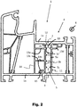
- the Figure 2 shows the same hollow chamber profile 1 as Figure 1 but without the external component or fastening means.
- the same reference symbols denote elements that are the same or at least have the same effect here and for the rest.
- the support web 13c between itself and the outer wall 1b of the hollow chamber profile 1 forms a further fastening channel 15 which runs in the longitudinal direction 6 of the extrusion of the hollow chamber profile 1 and which can be used to connect an external component (not shown) to the hollow chamber profile 1, in particular in one free end area of the hollow chamber profile 1.
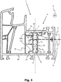
- the Figure 3 shows again the same hollow chamber profile 1 as Figure 1 , but with a different external component 3 'or an alternatively arranged, edge-profiled fastening means 2' (only shown schematically as a dashed line).
- the external component 3 ′ is arranged laterally on an end face 1c of the hollow chamber profile 1 and is connected to the hollow chamber profile 1 via the fastening means 2 ′, for example a screw.
- the fastening means 2 ' extends transversely to the channel longitudinal axis 7 into the area of the fastening channel 5 and through it, so that preferably both channel side walls 5a, 5b are penetrated by the fastening means 2' and serve to fix the fastening means 2 '.
- the Figure 4 shows in four partial images a) to d) possible configurations of the fastening channel 5 between the outer wall 1a and the outer wall 1b, as they are in the case of the hollow chamber profile 1 according to FIGS Figures 1 to 3 can be used.
- the support of the channel side walls 5a, 5b takes place via modified support webs 13, which are all designed similar to the support web 13c according to FIGS.
- the projections 5c are arranged at an angle of approximately 90 ° with respect to the channel side walls 5a, 5b.
- Two protrusions each, which start from different channel side walls 5a, 5b are exactly opposite one another, that is to say at the same height.
- Their free ends have a clear spacing A1 of preferably at most 2 mm transversely to the longitudinal axis 7 of the channel, so that spaces 17 effectively result within the fastening channel 5, which are actually delimited from one another, as has already been pointed out above.
- the projections 5c are arranged at an angle of approximately 90 ° with respect to the channel side walls 5a, 5b.
- Adjacent projections grouped in pairs and extending from different channel side walls 5a, 5b are offset from one another in the direction of the channel longitudinal axis 7, i.e. at different heights. Their free ends can overlap in projection along the channel longitudinal axis 7 or end exactly at the channel longitudinal axis 7, but have a clear distance A2 of preferably at most 2 mm in the direction of the channel longitudinal axis 7.
- the projections 5c are also arranged at an angle of approximately 90 ° with respect to the channel side walls 5a, 5b. In the direction of the longitudinal axis 7 of the channel, adjacent projections start alternately from different channel side walls 5a, 5b. Their free ends overlap in projection along the channel longitudinal axis 7 and have a clear distance A3 from the respective opposite channel side wall 5a, 5b of preferably at most 2 mm transversely to the channel longitudinal axis 7.
- the projections 5c are spaced apart in the direction of the longitudinal axis 7 of the channel at a distance of more than 2 mm.
- the fastening channel 5 is completely filled, i.e. from the outer wall 1a to the outer wall 1b, with a filler 18 (insulating foam, injection mortar or the like). This can take place in particular before the fastening means (not shown here) are introduced.
- a filler 18 insulating foam, injection mortar or the like
- FIG. 5 a section through a frame 19 for a door or a window, in particular a frame, which consists of several sections 1.1-1.4 of hollow chamber profiles 1 according to the invention (cf. Figures 1 to 4 ) is formed.
- the hollow chamber profile sections 1.1-1.4 are connected to one another in pairs in connection areas 20, preferably welded.
- a preferably metallic connecting element 21 in the form of an L-shaped connecting angle with its two legs 22 is in each of the connecting areas 20 in two interconnected hollow chamber profile sections 1.1-1.4 in the area of the respective Fastening channel 5 (dash-dotted) introduced. It can be held therein in a clamping force-fitting manner or in some other way (eg materially) in order to reinforce the connecting areas 20.
- This configuration is not restricted with regard to the type and number of connecting elements 21.
- the frame 19 can be connected to external components via the hollow chamber profile sections 1.1-1.4 in the manner described, for example with a reveal 3 (not shown here, cf. Figure 1 ).
Landscapes
- Engineering & Computer Science (AREA)
- Civil Engineering (AREA)
- Structural Engineering (AREA)
- Mechanical Engineering (AREA)
- Wing Frames And Configurations (AREA)
- Joining Of Corner Units Of Frames Or Wings (AREA)
Applications Claiming Priority (1)
| Application Number | Priority Date | Filing Date | Title |
|---|---|---|---|
| DE102020108412.9A DE102020108412A1 (de) | 2020-03-26 | 2020-03-26 | Extrudiertes Fenster- oder Tür-Hohlkammerprofil, System mit einem solchen Hohlkammerprofil und daraus hergestellter Rahmen |
Publications (2)
| Publication Number | Publication Date |
|---|---|
| EP3889384A1 true EP3889384A1 (fr) | 2021-10-06 |
| EP3889384B1 EP3889384B1 (fr) | 2025-10-22 |
Family
ID=74947241
Family Applications (1)
| Application Number | Title | Priority Date | Filing Date |
|---|---|---|---|
| EP21163246.8A Active EP3889384B1 (fr) | 2020-03-26 | 2021-03-17 | Profilé extrudé de section creuse de fenêtre ou de porte, système doté d'un tel profilé de section creuse et cadre fabriqué à partir de celui-ci |
Country Status (2)
| Country | Link |
|---|---|
| EP (1) | EP3889384B1 (fr) |
| DE (1) | DE102020108412A1 (fr) |
Cited By (1)
| Publication number | Priority date | Publication date | Assignee | Title |
|---|---|---|---|---|
| EP4390035A1 (fr) * | 2022-12-20 | 2024-06-26 | REHAU Industries SE & Co. KG | Ensemble de fixation, fenêtre le comprenant et porte le comprenant |
Families Citing this family (1)
| Publication number | Priority date | Publication date | Assignee | Title |
|---|---|---|---|---|
| DE102020130200A1 (de) | 2020-11-16 | 2022-05-19 | Aluplast Gmbh | System aus Blendrahmen-Hohlkammerprofil und Versteifungsprofil |
Citations (5)
| Publication number | Priority date | Publication date | Assignee | Title |
|---|---|---|---|---|
| DE4338181C1 (de) * | 1993-11-09 | 1994-12-15 | Rekord Fenster & Tueren Gmbh & | Kunststoff-Hohlprofil |
| EP0867591A2 (fr) * | 1997-03-25 | 1998-09-30 | Klaus Gayko | Fixation de ferrures sur portes ou fenêtres |
| EP1333145B1 (fr) * | 2002-01-31 | 2008-10-29 | L.M. dei F.lli Monticelli S.r.l. | Joint d'angle pour profilés creux métalliques de renforcement disposés à l'intérieur de profilés creux en matière plastique et son procédé de montage |
| EP2079895B1 (fr) | 2006-10-21 | 2015-09-30 | REHAU AG + Co | Profilé extrudé à cavité pour porte ou fenêtre |
| EP3556986A1 (fr) * | 2018-04-13 | 2019-10-23 | Veka AG | Combinaison de profilés de guidage pour une fenêtre dotée d'un caisson de volet roulant pourvu de trappe de révision côté extérieur du bâtiment |
Family Cites Families (3)
| Publication number | Priority date | Publication date | Assignee | Title |
|---|---|---|---|---|
| DE29507846U1 (de) | 1995-05-12 | 1995-08-03 | KBE-Vertriebsgesellschaft für Kunststoffprodukte GmbH, 66763 Dillingen | Blendrahmen aus thermoplastischem Kunststoff für Fenster und Türen |
| DE10212228A1 (de) | 2002-03-19 | 2003-10-02 | Kbe Profilsysteme Gmbh | Schwellenprofil |
| US10604989B2 (en) | 2018-01-08 | 2020-03-31 | Hawkes Design And Consulting, Llc | Window frame protection system for use in areas prone to storms |
-
2020
- 2020-03-26 DE DE102020108412.9A patent/DE102020108412A1/de active Pending
-
2021
- 2021-03-17 EP EP21163246.8A patent/EP3889384B1/fr active Active
Patent Citations (5)
| Publication number | Priority date | Publication date | Assignee | Title |
|---|---|---|---|---|
| DE4338181C1 (de) * | 1993-11-09 | 1994-12-15 | Rekord Fenster & Tueren Gmbh & | Kunststoff-Hohlprofil |
| EP0867591A2 (fr) * | 1997-03-25 | 1998-09-30 | Klaus Gayko | Fixation de ferrures sur portes ou fenêtres |
| EP1333145B1 (fr) * | 2002-01-31 | 2008-10-29 | L.M. dei F.lli Monticelli S.r.l. | Joint d'angle pour profilés creux métalliques de renforcement disposés à l'intérieur de profilés creux en matière plastique et son procédé de montage |
| EP2079895B1 (fr) | 2006-10-21 | 2015-09-30 | REHAU AG + Co | Profilé extrudé à cavité pour porte ou fenêtre |
| EP3556986A1 (fr) * | 2018-04-13 | 2019-10-23 | Veka AG | Combinaison de profilés de guidage pour une fenêtre dotée d'un caisson de volet roulant pourvu de trappe de révision côté extérieur du bâtiment |
Cited By (1)
| Publication number | Priority date | Publication date | Assignee | Title |
|---|---|---|---|---|
| EP4390035A1 (fr) * | 2022-12-20 | 2024-06-26 | REHAU Industries SE & Co. KG | Ensemble de fixation, fenêtre le comprenant et porte le comprenant |
Also Published As
| Publication number | Publication date |
|---|---|
| DE102020108412A1 (de) | 2021-09-30 |
| EP3889384B1 (fr) | 2025-10-22 |
Similar Documents
| Publication | Publication Date | Title |
|---|---|---|
| DE10136681A1 (de) | Rahmengestell | |
| EP0436869A2 (fr) | Liaison au niveau du raccordement entre poteau et traverse d'une structure porteuse pour ou un mur de façade | |
| DE102005044980B4 (de) | Stoßverbinder für Holz-/Aluminiumfassaden | |
| EP1840315B1 (fr) | Construction de cadre | |
| EP3889384B1 (fr) | Profilé extrudé de section creuse de fenêtre ou de porte, système doté d'un tel profilé de section creuse et cadre fabriqué à partir de celui-ci | |
| EP0995001B1 (fr) | Agencement d'une ferrure montee sur un cadre | |
| EP1840314B1 (fr) | Composant coupe-feu | |
| EP4102022B1 (fr) | Profilé de chambre creuse de fenêtre ou de porte, système doté d'un tel profilé de chambre creuse et châssis fabriqué à partir de celui-ci | |
| DE8708611U1 (de) | Träger für Fensterrahmen | |
| EP1290307B1 (fr) | Element de construction, utilisation d'un element de construction et procede de fabrication d'un element de construction | |
| EP2708693B1 (fr) | Cadre de battant ouvrant-coulissant | |
| EP1643049A2 (fr) | Construction avec profilés porteurs | |
| DE19613044A1 (de) | Pfosten-Sprossen-Konstruktion | |
| DE29509555U1 (de) | Schaltschrank mit Montageplatte als Einzel- oder Anreihschrank | |
| DE102009022827B4 (de) | Brandschutz- und/oder Rauchschutzschiebetür | |
| EP4102021B1 (fr) | Profilé de chambre creuse de fenêtre ou de porte, système doté d'un tel profilé de chambre creuse et châssis fabriqué à partir de celui-ci | |
| EP4424968B1 (fr) | Profilé composite, cadre et procédé de fabrication du profilé composite | |
| DE29805579U1 (de) | Wärmegedämmtes Verbundprofil | |
| EP0965714A1 (fr) | Fixation d'une ferrure | |
| EP2378045A2 (fr) | Disque en verre isolant | |
| EP1052360A1 (fr) | Profilé de jonction pour façades, fenêtres et similaires | |
| EP3656955B1 (fr) | Gâche | |
| AT408784B (de) | Anordnung zum befestigen von im wesentlichen u-förmigen führungsschienen für rolladen sowie baugruppe aus führungsschiene und halteteilen für eine solche anordnung | |
| DE10044951C1 (de) | Sprossenverbindung für Glasdächer bzw. Glasfassaden | |
| DE2553801A1 (de) | Rahmenkonstruktion fuer tueren, fenster u.dgl. |
Legal Events
| Date | Code | Title | Description |
|---|---|---|---|
| PUAI | Public reference made under article 153(3) epc to a published international application that has entered the european phase |
Free format text: ORIGINAL CODE: 0009012 |
|
| STAA | Information on the status of an ep patent application or granted ep patent |
Free format text: STATUS: THE APPLICATION HAS BEEN PUBLISHED |
|
| AK | Designated contracting states |
Kind code of ref document: A1 Designated state(s): AL AT BE BG CH CY CZ DE DK EE ES FI FR GB GR HR HU IE IS IT LI LT LU LV MC MK MT NL NO PL PT RO RS SE SI SK SM TR |
|
| RIN1 | Information on inventor provided before grant (corrected) |
Inventor name: EBERHARD, STEFAN Inventor name: HAUNS, JOACHIM Inventor name: FOERDERER, SEBASTIAN |
|
| STAA | Information on the status of an ep patent application or granted ep patent |
Free format text: STATUS: REQUEST FOR EXAMINATION WAS MADE |
|
| 17P | Request for examination filed |
Effective date: 20220126 |
|
| RBV | Designated contracting states (corrected) |
Designated state(s): AL AT BE BG CH CY CZ DE DK EE ES FI FR GB GR HR HU IE IS IT LI LT LU LV MC MK MT NL NO PL PT RO RS SE SI SK SM TR |
|
| STAA | Information on the status of an ep patent application or granted ep patent |
Free format text: STATUS: EXAMINATION IS IN PROGRESS |
|
| 17Q | First examination report despatched |
Effective date: 20230424 |
|
| GRAP | Despatch of communication of intention to grant a patent |
Free format text: ORIGINAL CODE: EPIDOSNIGR1 |
|
| STAA | Information on the status of an ep patent application or granted ep patent |
Free format text: STATUS: GRANT OF PATENT IS INTENDED |
|
| GRAJ | Information related to disapproval of communication of intention to grant by the applicant or resumption of examination proceedings by the epo deleted |
Free format text: ORIGINAL CODE: EPIDOSDIGR1 |
|
| STAA | Information on the status of an ep patent application or granted ep patent |
Free format text: STATUS: EXAMINATION IS IN PROGRESS |
|
| RIC1 | Information provided on ipc code assigned before grant |
Ipc: E06B 3/964 20060101ALI20250403BHEP Ipc: E06B 1/60 20060101ALI20250403BHEP Ipc: E06B 3/22 20060101AFI20250403BHEP |
|
| INTG | Intention to grant announced |
Effective date: 20250416 |
|
| GRAP | Despatch of communication of intention to grant a patent |
Free format text: ORIGINAL CODE: EPIDOSNIGR1 |
|
| STAA | Information on the status of an ep patent application or granted ep patent |
Free format text: STATUS: GRANT OF PATENT IS INTENDED |
|
| INTC | Intention to grant announced (deleted) | ||
| INTG | Intention to grant announced |
Effective date: 20250523 |
|
| GRAS | Grant fee paid |
Free format text: ORIGINAL CODE: EPIDOSNIGR3 |
|
| GRAA | (expected) grant |
Free format text: ORIGINAL CODE: 0009210 |
|
| STAA | Information on the status of an ep patent application or granted ep patent |
Free format text: STATUS: THE PATENT HAS BEEN GRANTED |
|
| AK | Designated contracting states |
Kind code of ref document: B1 Designated state(s): AL AT BE BG CH CY CZ DE DK EE ES FI FR GB GR HR HU IE IS IT LI LT LU LV MC MK MT NL NO PL PT RO RS SE SI SK SM TR |
|
| REG | Reference to a national code |
Ref country code: CH Ref legal event code: F10 Free format text: ST27 STATUS EVENT CODE: U-0-0-F10-F00 (AS PROVIDED BY THE NATIONAL OFFICE) Effective date: 20251022 Ref country code: GB Ref legal event code: FG4D Free format text: NOT ENGLISH |
|
| P01 | Opt-out of the competence of the unified patent court (upc) registered |
Free format text: CASE NUMBER: UPC_APP_7517_3889384/2025 Effective date: 20250918 |
|
| REG | Reference to a national code |
Ref country code: DE Ref legal event code: R096 Ref document number: 502021009002 Country of ref document: DE |
|
| REG | Reference to a national code |
Ref country code: IE Ref legal event code: FG4D Free format text: LANGUAGE OF EP DOCUMENT: GERMAN |
|
| REG | Reference to a national code |
Ref country code: NL Ref legal event code: MP Effective date: 20251022 |
|
| PG25 | Lapsed in a contracting state [announced via postgrant information from national office to epo] |
Ref country code: NL Free format text: LAPSE BECAUSE OF FAILURE TO SUBMIT A TRANSLATION OF THE DESCRIPTION OR TO PAY THE FEE WITHIN THE PRESCRIBED TIME-LIMIT Effective date: 20251022 |
|
| PG25 | Lapsed in a contracting state [announced via postgrant information from national office to epo] |
Ref country code: ES Free format text: LAPSE BECAUSE OF FAILURE TO SUBMIT A TRANSLATION OF THE DESCRIPTION OR TO PAY THE FEE WITHIN THE PRESCRIBED TIME-LIMIT Effective date: 20251022 |
|
| REG | Reference to a national code |
Ref country code: LT Ref legal event code: MG9D |
|
| PG25 | Lapsed in a contracting state [announced via postgrant information from national office to epo] |
Ref country code: NO Free format text: LAPSE BECAUSE OF FAILURE TO SUBMIT A TRANSLATION OF THE DESCRIPTION OR TO PAY THE FEE WITHIN THE PRESCRIBED TIME-LIMIT Effective date: 20260122 |
|
| PGFP | Annual fee paid to national office [announced via postgrant information from national office to epo] |
Ref country code: DE Payment date: 20260219 Year of fee payment: 6 |
|
| PG25 | Lapsed in a contracting state [announced via postgrant information from national office to epo] |
Ref country code: HR Free format text: LAPSE BECAUSE OF FAILURE TO SUBMIT A TRANSLATION OF THE DESCRIPTION OR TO PAY THE FEE WITHIN THE PRESCRIBED TIME-LIMIT Effective date: 20251022 Ref country code: FI Free format text: LAPSE BECAUSE OF FAILURE TO SUBMIT A TRANSLATION OF THE DESCRIPTION OR TO PAY THE FEE WITHIN THE PRESCRIBED TIME-LIMIT Effective date: 20251022 |
|
| PG25 | Lapsed in a contracting state [announced via postgrant information from national office to epo] |
Ref country code: RS Free format text: LAPSE BECAUSE OF FAILURE TO SUBMIT A TRANSLATION OF THE DESCRIPTION OR TO PAY THE FEE WITHIN THE PRESCRIBED TIME-LIMIT Effective date: 20260122 |
|
| PG25 | Lapsed in a contracting state [announced via postgrant information from national office to epo] |
Ref country code: IS Free format text: LAPSE BECAUSE OF FAILURE TO SUBMIT A TRANSLATION OF THE DESCRIPTION OR TO PAY THE FEE WITHIN THE PRESCRIBED TIME-LIMIT Effective date: 20260222 |