EP0965718A1 - Dispositif de fixation d'un dormant - Google Patents
Dispositif de fixation d'un dormant Download PDFInfo
- Publication number
- EP0965718A1 EP0965718A1 EP99111552A EP99111552A EP0965718A1 EP 0965718 A1 EP0965718 A1 EP 0965718A1 EP 99111552 A EP99111552 A EP 99111552A EP 99111552 A EP99111552 A EP 99111552A EP 0965718 A1 EP0965718 A1 EP 0965718A1
- Authority
- EP
- European Patent Office
- Prior art keywords
- frame
- reveal
- locking element
- teeth
- frame side
- Prior art date
- Legal status (The legal status is an assumption and is not a legal conclusion. Google has not performed a legal analysis and makes no representation as to the accuracy of the status listed.)
- Granted
Links
- 230000000903 blocking effect Effects 0.000 claims description 5
- 239000012858 resilient material Substances 0.000 claims 1
- 238000007789 sealing Methods 0.000 description 3
- 238000009434 installation Methods 0.000 description 1
- 230000003993 interaction Effects 0.000 description 1
- 238000004519 manufacturing process Methods 0.000 description 1
Images
Classifications
-
- E—FIXED CONSTRUCTIONS
- E06—DOORS, WINDOWS, SHUTTERS, OR ROLLER BLINDS IN GENERAL; LADDERS
- E06B—FIXED OR MOVABLE CLOSURES FOR OPENINGS IN BUILDINGS, VEHICLES, FENCES OR LIKE ENCLOSURES IN GENERAL, e.g. DOORS, WINDOWS, BLINDS, GATES
- E06B1/00—Border constructions of openings in walls, floors, or ceilings; Frames to be rigidly mounted in such openings
- E06B1/56—Fastening frames to the border of openings or to similar contiguous frames
- E06B1/60—Fastening frames to the border of openings or to similar contiguous frames by mechanical means, e.g. anchoring means
- E06B1/6046—Clamping means acting perpendicular to the wall opening; Fastening frames by tightening or drawing them against a surface parallel to the opening
Definitions
- the invention relates to a device for fastening a Frame on a fixed to a building wall Reveal frame.
- a device of the type mentioned has become known, for example, from AT-PS 349 718 .
- the frame for doors, windows or the like carries one Casement (window casement) or a door leaf (door) and is used to attach the window, door or the like on the structure (building wall).
- the window frame is usually not directly connected to the building, because in a recess of the building body is initially a so-called Soffit frame used and fixed to the building body is then connected to the reveal frame Fix frame.
- AT-PS 349 718 is a fastener for connection of the frame with the reveal frame, that a snap connection with one provided on the frame Can form locking element.
- a fastener for connection of the frame with the reveal frame, that a snap connection with one provided on the frame Can form locking element.
- the locking element When inserting the Blenrahmen transversely to the longitudinal direction of a frame section can the locking element with the fastener lock and by a fastening bolt in a certain Position can be locked.
- the interaction of the Fastener with the locking element requires that the fastener on the reveal frame and the locking element are attached to the frame so that the fastener and the locking element when inserting the Facing frame in the reveal frame. This sets the exact position of the fastener on the reveal frame and the locking element on the frame ahead. A post-correction in case of an offset Fasteners and locking elements are not possible.
- the object of the present invention is to be able to easily and non-destructively attach a frame to a soffit frame.
- This object is achieved in that the locking element at a the reveal frame side facing the window frame side of the frame portion in the longitudinal direction of the frame portion is movable to enable the operation.
- the slidable locking element can on the frame section are moved along to join the window frame to perform on the reveal frame.
- the locking element but can also be easily moved to one attached frame from a reveal frame quick way to take out.
- the frame can be damaged without forming through holes for blind frame screws be attached to the reveal frame.
- different depending on the purpose Frame can be used in a reveal frame.
- the frame can be replaced at any time can also be assembled or disassembled without specialist knowledge.
- the displaceability of the locking element on the frame section allows individual frame sections one after the other on the associated reveal frame sections to attach and the frame in this way position or adjust its position in the reveal frame.
- the fastener is by several protruding from the soffit frame side Teeth and the blocking element by several from the frame side protruding ratchet teeth formed.
- the teeth and ratchet teeth interlock so that a stable, fixed connection of the frame to the Reveal frame can arise.
- the toothing enables to permanently attach the frame to the reveal frame.
- a further development of this embodiment is characterized by this that the teeth and the soffit frame side unite angles open towards the outside of the building wall less than 90 ° and the ratchet teeth and the frame side one angles open towards the inside of the building wall limit greater than 90 ° and that the reveal frame one Has stop for inserting the frame.
- the Inclination or inclination of the teeth and locking teeth leads this means that the frame easily starts from an interior of the building towards the outside of the building can be pushed into the reveal frame.
- the sealing element can be easily squeezed so that the frame is mounted in a manner in the reveal frame in which the ratchet teeth reach behind the teeth.
- the frame can transversely to the longitudinal direction of the frame profile of the frame be pushed in until the teeth lock and ratchet teeth occurs.
- the fasteners can be different on the reveal frame Way trained or attached become. However, it is preferred to attach the fastener unscrew the reveal frame side. The craftsman can then select locations on the building body where a fastening of the frame with the reveal frame with Help of the fastener is particularly cheap.
- To the Reveal frames can also have several on the reveal frame side Fasteners distributed over the reveal frame side be screwed on. This increases the stability of the attachment, when the frame is fixed with the reveal frame becomes.
- the slidable design of the locking element on the The frame side is particularly possible if the The frame side is profiled, the profiles Form guide grooves for holding the locking element.
- the guide grooves ensure defined guidance and simultaneous mounting of the locking element, so that this is precise be moved to lock the ratchet teeth and teeth can.
- the teeth can be fine tuned accordingly a graded positioning of the frame on the building body to reach.
- a detachable bracket perform the locking element.
- the locking element can in snap in, snap in or snap in the guide grooves become.
- the manufacture of the heels of the locking element from a compliant Material has the advantage that the paragraphs of the Locking element on the groove flanks or a groove base of the guide grooves can support resiliently. This enables one Bridging tolerances when the teeth mesh and ratchet teeth.
- the blocking element made of a flexible material (plastic) can be within the plane or parallel to the plane of the The window or the door.
- the actuation of the locking element for locking the locking element and fasteners can be used in a variety of ways be performed.
- In a preferred embodiment is on a transversely to the frame side arranged outer frame or inner frame surface in the longitudinal direction recess provided in the frame section, from which a slide connected to the locking element protrudes.
- the Locking also ensures a secure connection of the Frame with the reveal frame, so that third parties Do not remove the frame from the reveal frame from the outside can (security against burglary).
- the increase in stability of the connection of the frame with the reveal frame is increased even further when on everyone the interconnected frame sections and reveal frame sections at least one device according to the invention is available.
- the frame also could have a fixed locking element if the Reveal frame in the longitudinal direction of a reveal frame section movably attached fastener as Counterpart to the locking element carries. According to the invention it depends on the locking element and the fastener relative to each other in the longitudinal direction of the frame section or reveal frame section slidably are.
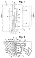
- a reveal frame 1 is fixedly attached to a building wall 2.
- a device 3 framed in dashed lines in the figure enables a frame 4 to be attached to the reveal frame 1.
- the figure shows the not yet attached state of the frame 4 to the reveal frame 1.
- the joint 7 which forms between a soffit frame side 5 and a window frame side 6 can be closed or covered by a cover strip. The joint 7 is then not visible from the inside of the building.
- a window sash 10 is rotatably attached to the frame 4 via fittings 8 and 9.
- a fastening means 11 is on the reveal frame side 5 provided for connection to a locking element 12.
- the fastener 11 has teeth 13 and is on the reveal frame side 5 screwed and fixed in place.
- the Locking element is displaceable in the direction of arrow 14, so that the fastener 11 and the locking element 12 relative can be moved towards each other.
- the blocking element 12 has ratchet teeth 15 which engage teeth 13 can be brought, as shown in Fig. 2 in more detail and is described for this figure.
- the locking element 12 is connected to a slide 16, which is an increase 17 for its operation.
- a recess 18 enables the slider 16 to be slidably formed or the blocking element 12.
- the reveal frame 1 is firmly connected to the building wall 2 and has an L-shaped cross-sectional shape with legs 20 and 21, the leg 21 being a stop for a frame side 22 forms.
- a sealing element 23 is attached to a soffit frame side 24 in order to be able to seal the area between the soffit frame side 24 and the frame side 22 and to ensure an elastic stop for the frame side 22.
- the frame 4 is profiled so that on one Frame side 25 guide grooves 26 and 27 formed are.
- paragraphs 28 and 29 of the locking element 12 used resiliently, so that the locking element 12 in one direction out of the drawing plane can be moved. Consequently, the teeth 13 of the fastener 11 with the locking teeth 15 of the locking element 12 can be brought into engagement, as shown in FIG. 2 is shown.
- the movement of the locking element 12 can by operating the slide 16.
- the assessment 17 of the slide 16 forms a non-slip surface One-handed operation.
- a cover strip 30 is between the reveal frame 1 and the frame 4 attached.
Landscapes
- Engineering & Computer Science (AREA)
- Mechanical Engineering (AREA)
- Civil Engineering (AREA)
- Structural Engineering (AREA)
- Door And Window Frames Mounted To Openings (AREA)
- Mutual Connection Of Rods And Tubes (AREA)
- Package Frames And Binding Bands (AREA)
- Wing Frames And Configurations (AREA)
- Body Structure For Vehicles (AREA)
Applications Claiming Priority (2)
| Application Number | Priority Date | Filing Date | Title |
|---|---|---|---|
| DE29811003U DE29811003U1 (de) | 1998-06-19 | 1998-06-19 | Einrichtung zur Befestigung eines Blendrahmens |
| DE29811003U | 1998-06-19 |
Publications (2)
| Publication Number | Publication Date |
|---|---|
| EP0965718A1 true EP0965718A1 (fr) | 1999-12-22 |
| EP0965718B1 EP0965718B1 (fr) | 2001-05-23 |
Family
ID=8058783
Family Applications (1)
| Application Number | Title | Priority Date | Filing Date |
|---|---|---|---|
| EP99111552A Expired - Lifetime EP0965718B1 (fr) | 1998-06-19 | 1999-06-15 | Ensemble de fixation d'un dormant |
Country Status (3)
| Country | Link |
|---|---|
| EP (1) | EP0965718B1 (fr) |
| AT (1) | ATE201478T1 (fr) |
| DE (2) | DE29811003U1 (fr) |
Cited By (2)
| Publication number | Priority date | Publication date | Assignee | Title |
|---|---|---|---|---|
| EP3779113A1 (fr) | 2019-08-14 | 2021-02-17 | Uniform S.p.A. | Porte/fenêtre à battant fixe pour l'extérieur |
| EP4495364A1 (fr) * | 2023-07-21 | 2025-01-22 | Johan van Driesum Beheer B.V. | Dispositif de raccordement d'un cadre préfabriqué à un cadre de montage |
Families Citing this family (1)
| Publication number | Priority date | Publication date | Assignee | Title |
|---|---|---|---|---|
| DE102006012390A1 (de) * | 2006-03-17 | 2007-09-20 | PHI Technik für Fenster und Türen GmbH | Keilvorrichtung |
Citations (10)
| Publication number | Priority date | Publication date | Assignee | Title |
|---|---|---|---|---|
| GB352180A (en) * | 1930-05-23 | 1931-07-09 | Percy Bilton | Improvements in or relating to doors |
| DE1659749B1 (de) * | 1966-06-02 | 1970-10-01 | Eltreva Ag | Wand- und Deckenanschluss fuer feststehende Tuer- oder Fensterrahmen |
| AT349718B (de) | 1975-10-01 | 1979-04-25 | Kraushofer Johann | Einrichtung zur befestigung des stockrahmens von festern oder tueren an einem in der wand verankerten blindrahmen |
| DE2917981B1 (de) * | 1979-05-04 | 1980-08-28 | Top Element Bauelemente | Vorrichtung zum Befestigen einer Tuerzarge in der Tueroeffnung einer Staenderwand |
| GB2163191A (en) * | 1984-07-23 | 1986-02-19 | William Graham Hitchins | Modular building component |
| DE8914329U1 (de) * | 1989-12-06 | 1990-03-29 | MEKUWA Metall- und Kunststoff-Fertigungs-Gesellschaft mbH, 6082 Mörfelden-Walldorf | Vorrichtung zur Befestigung eines Fensters in einer Wandöffnung, insbesondere in der Karosserie eines Fahrzeugs |
| DE4135125A1 (de) * | 1991-10-24 | 1993-04-29 | Weru Ag | Haltevorrichtung fuer einen rahmen eines fensters, einer tuer o. dgl. |
| DE9407415U1 (de) * | 1994-05-04 | 1994-07-07 | Siegenia-Frank Kg, 57074 Siegen | Abschlußelement für Wandöffnungen in Gebäuden od.dgl. |
| FR2726027A1 (fr) * | 1994-10-20 | 1996-04-26 | Clima Neu Sa | Bloc-porte preregle pour cloison, cloison modulaire, procede d'assemblage d'un bloc-porte et procede d'installation d'un bloc-porte dans une cloison |
| WO1997017515A1 (fr) * | 1995-11-07 | 1997-05-15 | Anthony David Marks | Procede d'installation et de fixation de placage, par broche et coulisse |
-
1998
- 1998-06-19 DE DE29811003U patent/DE29811003U1/de not_active Expired - Lifetime
-
1999
- 1999-06-15 DE DE59900098T patent/DE59900098D1/de not_active Expired - Fee Related
- 1999-06-15 AT AT99111552T patent/ATE201478T1/de not_active IP Right Cessation
- 1999-06-15 EP EP99111552A patent/EP0965718B1/fr not_active Expired - Lifetime
Patent Citations (10)
| Publication number | Priority date | Publication date | Assignee | Title |
|---|---|---|---|---|
| GB352180A (en) * | 1930-05-23 | 1931-07-09 | Percy Bilton | Improvements in or relating to doors |
| DE1659749B1 (de) * | 1966-06-02 | 1970-10-01 | Eltreva Ag | Wand- und Deckenanschluss fuer feststehende Tuer- oder Fensterrahmen |
| AT349718B (de) | 1975-10-01 | 1979-04-25 | Kraushofer Johann | Einrichtung zur befestigung des stockrahmens von festern oder tueren an einem in der wand verankerten blindrahmen |
| DE2917981B1 (de) * | 1979-05-04 | 1980-08-28 | Top Element Bauelemente | Vorrichtung zum Befestigen einer Tuerzarge in der Tueroeffnung einer Staenderwand |
| GB2163191A (en) * | 1984-07-23 | 1986-02-19 | William Graham Hitchins | Modular building component |
| DE8914329U1 (de) * | 1989-12-06 | 1990-03-29 | MEKUWA Metall- und Kunststoff-Fertigungs-Gesellschaft mbH, 6082 Mörfelden-Walldorf | Vorrichtung zur Befestigung eines Fensters in einer Wandöffnung, insbesondere in der Karosserie eines Fahrzeugs |
| DE4135125A1 (de) * | 1991-10-24 | 1993-04-29 | Weru Ag | Haltevorrichtung fuer einen rahmen eines fensters, einer tuer o. dgl. |
| DE9407415U1 (de) * | 1994-05-04 | 1994-07-07 | Siegenia-Frank Kg, 57074 Siegen | Abschlußelement für Wandöffnungen in Gebäuden od.dgl. |
| FR2726027A1 (fr) * | 1994-10-20 | 1996-04-26 | Clima Neu Sa | Bloc-porte preregle pour cloison, cloison modulaire, procede d'assemblage d'un bloc-porte et procede d'installation d'un bloc-porte dans une cloison |
| WO1997017515A1 (fr) * | 1995-11-07 | 1997-05-15 | Anthony David Marks | Procede d'installation et de fixation de placage, par broche et coulisse |
Cited By (3)
| Publication number | Priority date | Publication date | Assignee | Title |
|---|---|---|---|---|
| EP3779113A1 (fr) | 2019-08-14 | 2021-02-17 | Uniform S.p.A. | Porte/fenêtre à battant fixe pour l'extérieur |
| EP4495364A1 (fr) * | 2023-07-21 | 2025-01-22 | Johan van Driesum Beheer B.V. | Dispositif de raccordement d'un cadre préfabriqué à un cadre de montage |
| NL2035449B1 (nl) * | 2023-07-21 | 2025-02-04 | Johan Van Driesum Beheer B V | Inrichting voor het verbinden van een prefab kozijn met een stelkozijn |
Also Published As
| Publication number | Publication date |
|---|---|
| EP0965718B1 (fr) | 2001-05-23 |
| DE59900098D1 (de) | 2001-06-28 |
| DE29811003U1 (de) | 1998-09-03 |
| ATE201478T1 (de) | 2001-06-15 |
Similar Documents
| Publication | Publication Date | Title |
|---|---|---|
| DE202015103240U1 (de) | Abdeckleiste zur Befestigung an einem Fensterrahmen | |
| DE9407415U1 (de) | Abschlußelement für Wandöffnungen in Gebäuden od.dgl. | |
| AT412360B (de) | Insektenschutzgitter mit einem rahmen | |
| EP0965718B1 (fr) | Ensemble de fixation d'un dormant | |
| DE4423944A1 (de) | Tür oder Fenster | |
| DE202013009721U1 (de) | Führungsprofil | |
| DE19808847C2 (de) | Tür- oder Fensterbeschlag | |
| EP3715578A1 (fr) | Porte de protection contre les insectes | |
| DE2221988A1 (de) | Vorrichtung zur fuehrung von rolladen oder aehnlichen verstellbaren teilen | |
| DE69710027T2 (de) | Monodirektionaler Treibstangenverschluss | |
| EP0823522A2 (fr) | Engrenage à levier dans une feuillure pour fenêtres ou portes | |
| DE2411114C3 (de) | Beschlag für einen aus profilierten Rahmenteilen bestehenden Flügel von Fenstern, Türen od. dgl. | |
| DE8222539U1 (de) | Fenster- oder tuerfluegel | |
| DE9308713U1 (de) | Eck- oder Sprossenverbindung von Rahmenprofilen | |
| EP3194697B1 (fr) | Ensemble ferrure | |
| DE202018104841U1 (de) | Verschlusselement zum Verschließen einer Öffnung | |
| DE6608529U (de) | Fenster- oder tuerkonstruktion. | |
| DE19828267A1 (de) | Fenster- oder Türbeschlag | |
| EP1041236A2 (fr) | Carter de volet à rouleau | |
| AT412799B (de) | Befestigungselement für mehrteilige rahmen für fenster oder dergleichen | |
| DE8708724U1 (de) | Zweiteiliger Rahmen für Fenster, Türen oder Dachluken | |
| DE8335667U1 (de) | Fensterrahmen für Wohnwagen u.dgl. | |
| DE2328742A1 (de) | Fensterrahmenausfuehrung | |
| DE1604208C3 (de) | Spaltlüftungsvorrichtung mit einer Lüftungsklappe | |
| DE1921370A1 (de) | Treibstangenbeschlag fuer Fensterfluegel od.dgl. |
Legal Events
| Date | Code | Title | Description |
|---|---|---|---|
| PUAI | Public reference made under article 153(3) epc to a published international application that has entered the european phase |
Free format text: ORIGINAL CODE: 0009012 |
|
| AK | Designated contracting states |
Kind code of ref document: A1 Designated state(s): AT DE FR GB |
|
| AX | Request for extension of the european patent |
Free format text: AL;LT;LV;MK;RO;SI |
|
| 17P | Request for examination filed |
Effective date: 19991202 |
|
| 17Q | First examination report despatched |
Effective date: 20000211 |
|
| AKX | Designation fees paid |
Free format text: AT DE FR GB |
|
| GRAG | Despatch of communication of intention to grant |
Free format text: ORIGINAL CODE: EPIDOS AGRA |
|
| RTI1 | Title (correction) |
Free format text: FIXING ARRANGEMENT FOR FASTENING A FIXED WINDOW OR DOOR FRAME |
|
| GRAG | Despatch of communication of intention to grant |
Free format text: ORIGINAL CODE: EPIDOS AGRA |
|
| GRAH | Despatch of communication of intention to grant a patent |
Free format text: ORIGINAL CODE: EPIDOS IGRA |
|
| GRAH | Despatch of communication of intention to grant a patent |
Free format text: ORIGINAL CODE: EPIDOS IGRA |
|
| GRAA | (expected) grant |
Free format text: ORIGINAL CODE: 0009210 |
|
| AK | Designated contracting states |
Kind code of ref document: B1 Designated state(s): AT DE FR GB |
|
| REF | Corresponds to: |
Ref document number: 201478 Country of ref document: AT Date of ref document: 20010615 Kind code of ref document: T |
|
| REF | Corresponds to: |
Ref document number: 59900098 Country of ref document: DE Date of ref document: 20010628 |
|
| GBT | Gb: translation of ep patent filed (gb section 77(6)(a)/1977) |
Effective date: 20010809 |
|
| ET | Fr: translation filed | ||
| REG | Reference to a national code |
Ref country code: GB Ref legal event code: IF02 |
|
| PLBE | No opposition filed within time limit |
Free format text: ORIGINAL CODE: 0009261 |
|
| STAA | Information on the status of an ep patent application or granted ep patent |
Free format text: STATUS: NO OPPOSITION FILED WITHIN TIME LIMIT |
|
| 26N | No opposition filed | ||
| PGFP | Annual fee paid to national office [announced via postgrant information from national office to epo] |
Ref country code: FR Payment date: 20050608 Year of fee payment: 7 |
|
| PGFP | Annual fee paid to national office [announced via postgrant information from national office to epo] |
Ref country code: GB Payment date: 20050613 Year of fee payment: 7 |
|
| PGFP | Annual fee paid to national office [announced via postgrant information from national office to epo] |
Ref country code: AT Payment date: 20050629 Year of fee payment: 7 |
|
| PG25 | Lapsed in a contracting state [announced via postgrant information from national office to epo] |
Ref country code: GB Free format text: LAPSE BECAUSE OF NON-PAYMENT OF DUE FEES Effective date: 20060615 Ref country code: AT Free format text: LAPSE BECAUSE OF NON-PAYMENT OF DUE FEES Effective date: 20060615 |
|
| GBPC | Gb: european patent ceased through non-payment of renewal fee |
Effective date: 20060615 |
|
| REG | Reference to a national code |
Ref country code: FR Ref legal event code: ST Effective date: 20070228 |
|
| PG25 | Lapsed in a contracting state [announced via postgrant information from national office to epo] |
Ref country code: FR Free format text: LAPSE BECAUSE OF NON-PAYMENT OF DUE FEES Effective date: 20060630 |
|
| PGFP | Annual fee paid to national office [announced via postgrant information from national office to epo] |
Ref country code: DE Payment date: 20080624 Year of fee payment: 10 |
|
| PG25 | Lapsed in a contracting state [announced via postgrant information from national office to epo] |
Ref country code: DE Free format text: LAPSE BECAUSE OF NON-PAYMENT OF DUE FEES Effective date: 20100101 |