EP0965725B1 - Einrichtung zur Endstellungsanzeige eines bidirektionalen mobilen Elements, insbesondere einer Rolladenwickelwelle, und Antriebsvorrichtung eines bidirektionalen mobilen Elements ausgerüstet mit solcher Endstellungseinrichtung - Google Patents
Einrichtung zur Endstellungsanzeige eines bidirektionalen mobilen Elements, insbesondere einer Rolladenwickelwelle, und Antriebsvorrichtung eines bidirektionalen mobilen Elements ausgerüstet mit solcher Endstellungseinrichtung Download PDFInfo
- Publication number
- EP0965725B1 EP0965725B1 EP99490017A EP99490017A EP0965725B1 EP 0965725 B1 EP0965725 B1 EP 0965725B1 EP 99490017 A EP99490017 A EP 99490017A EP 99490017 A EP99490017 A EP 99490017A EP 0965725 B1 EP0965725 B1 EP 0965725B1
- Authority
- EP
- European Patent Office
- Prior art keywords
- limit switch
- mobile element
- processing means
- mode
- motorised
- Prior art date
- Legal status (The legal status is an assumption and is not a legal conclusion. Google has not performed a legal analysis and makes no representation as to the accuracy of the status listed.)
- Expired - Lifetime
Links
- 238000001514 detection method Methods 0.000 claims description 14
- 230000006870 function Effects 0.000 claims description 6
- 230000001960 triggered effect Effects 0.000 claims description 2
- 238000009795 derivation Methods 0.000 claims 1
- 210000000056 organ Anatomy 0.000 description 9
- 230000000903 blocking effect Effects 0.000 description 8
- 238000004804 winding Methods 0.000 description 4
- 230000000712 assembly Effects 0.000 description 2
- 238000000429 assembly Methods 0.000 description 2
- 238000006243 chemical reaction Methods 0.000 description 2
- 238000006073 displacement reaction Methods 0.000 description 2
- 230000000694 effects Effects 0.000 description 2
- 230000009471 action Effects 0.000 description 1
- 230000005540 biological transmission Effects 0.000 description 1
- 230000008859 change Effects 0.000 description 1
- 239000003638 chemical reducing agent Substances 0.000 description 1
- 238000009429 electrical wiring Methods 0.000 description 1
- 230000004048 modification Effects 0.000 description 1
- 238000012986 modification Methods 0.000 description 1
- 230000007935 neutral effect Effects 0.000 description 1
- 238000009418 renovation Methods 0.000 description 1
- 230000007704 transition Effects 0.000 description 1
- 238000011144 upstream manufacturing Methods 0.000 description 1
- 238000012800 visualization Methods 0.000 description 1
Images
Classifications
-
- H—ELECTRICITY
- H02—GENERATION; CONVERSION OR DISTRIBUTION OF ELECTRIC POWER
- H02P—CONTROL OR REGULATION OF ELECTRIC MOTORS, ELECTRIC GENERATORS OR DYNAMO-ELECTRIC CONVERTERS; CONTROLLING TRANSFORMERS, REACTORS OR CHOKE COILS
- H02P25/00—Arrangements or methods for the control of AC motors characterised by the kind of AC motor or by structural details
- H02P25/02—Arrangements or methods for the control of AC motors characterised by the kind of AC motor or by structural details characterised by the kind of motor
- H02P25/04—Single phase motors, e.g. capacitor motors
-
- E—FIXED CONSTRUCTIONS
- E06—DOORS, WINDOWS, SHUTTERS, OR ROLLER BLINDS IN GENERAL; LADDERS
- E06B—FIXED OR MOVABLE CLOSURES FOR OPENINGS IN BUILDINGS, VEHICLES, FENCES OR LIKE ENCLOSURES IN GENERAL, e.g. DOORS, WINDOWS, BLINDS, GATES
- E06B9/00—Screening or protective devices for wall or similar openings, with or without operating or securing mechanisms; Closures of similar construction
- E06B9/56—Operating, guiding or securing devices or arrangements for roll-type closures; Spring drums; Tape drums; Counterweighting arrangements therefor
- E06B9/80—Safety measures against dropping or unauthorised opening; Braking or immobilising devices; Devices for limiting unrolling
- E06B9/82—Safety measures against dropping or unauthorised opening; Braking or immobilising devices; Devices for limiting unrolling automatic
- E06B9/88—Safety measures against dropping or unauthorised opening; Braking or immobilising devices; Devices for limiting unrolling automatic for limiting unrolling
-
- H—ELECTRICITY
- H02—GENERATION; CONVERSION OR DISTRIBUTION OF ELECTRIC POWER
- H02P—CONTROL OR REGULATION OF ELECTRIC MOTORS, ELECTRIC GENERATORS OR DYNAMO-ELECTRIC CONVERTERS; CONTROLLING TRANSFORMERS, REACTORS OR CHOKE COILS
- H02P23/00—Arrangements or methods for the control of AC motors characterised by a control method other than vector control
- H02P23/24—Controlling the direction, e.g. clockwise or counterclockwise
-
- E—FIXED CONSTRUCTIONS
- E06—DOORS, WINDOWS, SHUTTERS, OR ROLLER BLINDS IN GENERAL; LADDERS
- E06B—FIXED OR MOVABLE CLOSURES FOR OPENINGS IN BUILDINGS, VEHICLES, FENCES OR LIKE ENCLOSURES IN GENERAL, e.g. DOORS, WINDOWS, BLINDS, GATES
- E06B9/00—Screening or protective devices for wall or similar openings, with or without operating or securing mechanisms; Closures of similar construction
- E06B9/56—Operating, guiding or securing devices or arrangements for roll-type closures; Spring drums; Tape drums; Counterweighting arrangements therefor
- E06B9/68—Operating devices or mechanisms, e.g. with electric drive
- E06B2009/6809—Control
- E06B2009/6872—Control using counters to determine shutter position
Definitions
- the present invention relates to an end detection device stroke of a bi-directionally movable member, in particular a drum roller shutter, provided with means for adjusting and recording its positions limit switch, as well as a device for driving a bi-directionally movable member equipped with such a limit switch detection device.
- the invention may also be used in all areas of economic activity in which we want limit the travel of a bi-directionally movable member between two points.
- Means for comparing the position of the drum with the saved end positions then allow the detection of positions in which the movements of the drum must be blocked.
- a first drawback of such mechanical assemblies is that they are located at the level of the drum and therefore require difficult interventions. Indeed, the roller shutter drums are generally hidden in a chest placed in height and the adjustment of the ends must be run blind.
- the logic processing unit has two switches ensuring both the selection of the engine operating mode, the initialization in programming mode and limit switch programming.
- the transition to programming mode is initiated when the two switches are closed.
- the motor is then switched off.
- ULT waits for the operator by switching one of the two command switches the engine to run.
- the switching of the two switches in the closed position, for a time given means to the ULT the new position of the limit switches.
- the programming sequence is heavy and requires engine shutdown for time periods. It forces the operator to immobilize the engine for the first time during the phase initialization in programming mode, and a second time for at least one determined time, to signify to the system the new end position of race.
- the purpose of the present invention is to provide a device for end of stroke detection which overcomes the aforementioned drawbacks and allows make adjustments to their position remotely.
- Another object of the present invention is to provide a limit switch detection device which reduces the risk of malfunctionning.
- Another object of the present invention is to provide a end-of-travel detection device which can be adjusted by real visualization of the positions in which one wishes to block the organ mobile concerned.
- the present invention relates to an end detection device stroke of a bi-directionally movable member, in particular a drum roller shutter, provided with means for adjusting and recording its positions limit switch, said device comprising motor means drive of the movable member, means for controlling the position of the movable member, means for comparing said position of the member mobile with the saved end positions, and digital processing means capable of operate in two different modes, one says "normal”, the other says “Setting”, said control means being provided capable of giving a image of the position of the organ in the form of a digitized input signal processing means, and said adjusting means comprising means electrics for selecting the mode of use of the processing means and end positions for their storage, said selection means being provided suitable for allowing the adjustment of the end-of-travel positions at the stolen, while the movable member is actuated, without stopping the motor means for timeout periods.
- the invention also relates to a drive device a bi-directionally movable member equipped with a device for detecting limit switch as described above.
- the present invention relates to an end detection device stroke of a bi-directionally movable member, in particular drum roller shutter, provided with means for adjusting and recording its positions limit switch.
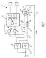
- the limit switch detection device comprises means 1 for controlling the position of the movable member and means for comparing said position of the member mobile with the saved end positions.
- digital processing means 30 capable of operating according to two different modes, one says "normal” and the other says “setting”.
- the first authorizes, for example, the tracking and blocking of the movable member when it arrives at the level of the limit positions saved while the second authorizes, in particular, the adjustment and / or modification thereof.
- control means are provided capable of give an image of the position of the organ in the form of a digitized signal at the input of said processing means 30.
- control means are, for example, means for counting pulses delivered by cooperating magnetic sensors with a magnetic field, mobile in relation to said organ.
- the means for adjusting the position of the end of race include electrical means 18,20; 18, 40 selection of mode of use of the processing means 30, said electrical means being further provided capable of authorizing the selection of the end positions of race for their memorization, when the movable member has arrived at the position desired.
- a digitized signal for tracking the positions of the mobile organ, digital processing means and means of electrical selection thus allows, for example, the realization of electrical wiring, allowing remote adjustment of end positions race and facilitating operator interventions.
- Said processing means 30 are provided capable of producing, for example, counting functions from the signal giving the image of the position of the organ. They are provided for this, in particular, with one or more counters 32.
- Said processing means 30 also allow, by example, comparing the value of the counter (s) 32 with a value corresponding to the end-of-travel positions, these being provided for stored, in particular, in a memory module 33.
- Said processing means 30 also allow, by example, storing the limit values set in said module memory 33 and / or the issuance of a blocking order of the movable member in the event of correspondence between the values appearing in the counter (s) 32 and those stored in a memory module 33.
- Said processing means 30 are further provided suitable, for example, to authorize a switching of their operation between the “normal” mode and “setting” mode, in particular using data input established from the electrical current also allowing the setting movement of the mobile organ.
- said processing means 30 carry out so, for example, counting functions, comparison of values counted with the limit values, and issuance of blocking order in match, while in "setting” mode, the comparison of the values counted with the limit values is possibly inhibited and replaced by the news storage function limit values set.
- said processing means 30 take into account counts, for example, the signal or signals giving the image of the position of the mobile organ and / or the signal or signals determining their mode of operation. On exit, they issue, for example, blocking orders of said movable member.
- Said processing means 30 comprise, for example, a microprocessor 34 capable of implementing software allowing the realization, in particular, of said counting functions, comparison, storage, switching and / or blocking order transmission.
- Said counters 32 consist, for example, of a mobile unit position counter, a limit switch and / or of a time counter.
- said selection means 18, 20; 18, 40 are provided suitable for allowing the adjustment of the end-of-travel positions at the fly, that is to say during the actual movement of the movable member.
- the stored values then correspond, for example, to the value of counter 32 after stopping said movable member at the position to be saved as end position.
- the present invention also relates to a device for driving a bi-directionally movable member equipped with a such end of stroke detection device.
- Said drive device comprises, for example, motor means 10 for driving the movable member and / or means for selection 16 of the operating mode of said motor means 10.
- Said means 16 for selecting the operating mode said motor means 10 allow an operator to choose, for example, the direction of movement of said movable member and / or keeping it stationary.
- said processing means 30 are connected by mounting in bypass on a supply line 35 provided between said motor means 10 and said means 16 for selecting the operating mode of said motor means 10.
- Said means 16 for selecting the operating mode said motor means 10 are, for example, connected to the network, marked 17, and are optionally provided capable of isolating said supply line 35 from this one. This prevents said means 1 for controlling and / or processing 30 are permanently powered. Furthermore, such a provision allows, if desired, to control multiple motors from one control point unique.
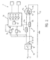
- said supply line 35 consists, for example, of two cables 12a, 12b each allowing, for example, the supply of said motor means 10 for operation in a given direction and said means 18, 20; 18, 40 for selecting the operating mode of the processing means 30 digital and end positions consist of means of setting under simultaneous tension of said two cables 12a, 12b.
- Said simultaneous energization is planned to be temporary. It ceases, for example, when the movable member has arrived at the desired position to define an end position.
- said setting means under simultaneous tension of said two cables 12a, 12b comprise a push button 40 able to close a short circuit line 41 provided between said two cables 12a, 12b.
- This first embodiment of the setting means under simultaneous tension of the two cables 12a, 12b is illustrated in FIG. 2.
- a tool 20, 40 distinct from the tool 18 for controlling the direction of rotation of the motor, to switch from the mode "Normal” in "programming mode".
- Said motor means 10 consist, in particular, of a motor having, for example, two windings 11a, 11b allowing each rotation in a given direction.
- Said windings 11a, 11b are provided, in particular, between one of the cables 12a, 12b, forming a phase line and a neutral line 13, possibly connected to a common point 14 provided between the said windings 11a, 11b.
- a capacity 15 is, for example, provided at the level of said windings 11a, 11b between their terminals opposite the common point 14.
- Said drive device further comprises, by example, blocking means 19 of said motor means 10. They are consisting, in particular, of a circuit breaker member provided on each of the cables 12a, 12b.
- Said means 16 for selecting the operating mode said motor means 10 and / or said selection means 18, 20; 18, 40 from operating mode of the processing means 30 and the end positions limit switches consist, for example, of a three-position switch. This is located, in particular, between sector 17 and said supply line 35.
- Said switch could be constituted, for example, for said means 16 for selecting the operating mode of the means motor 10, of a direction reversing button 18, and for said means of the mode of selection of the processing means 30, of a button inverter 20.
- one of the terminals corresponds to a direction of movement of the movable member, the second to the other direction of movement of this and the third at the stop of the engine means.
- a first of the terminals corresponds to the mode for setting a first end position, a second to the setting mode of the second end position and the third terminal in normal operating mode.
- the operator actuates the inverter 18 to connect the phase line 12a with the sector and allow the displacement of the movable member in the direction concerned. Simultaneously, the other phase line 12b is cut at using the circuit breaker 19 provided thereon, as in normal mode.
- the processing means 30 being connected in bypass to said phase lines 12a, 12b, they then note the appearance at the input of a state different from the normal state, each of said lines 12a, 12b being supplied, instead of just one, upstream of the locking means 19.
- the mode limit switch is activated, motor in rotation.
- Said drive device further comprises, possibly to promote the functioning of said processing means 30, a stabilized supply 36 between them and said supply line 35.
- processing means digital 30 It also includes, possibly, means 37 for analog / digital conversion provided between said processing means digital 30 and said selection means 18, 20; 18, 40 of the operation of said processing means 30.
- Said means of conversion include, among others, a voltage divider, a rectifier and / or a filter.
Landscapes
- Engineering & Computer Science (AREA)
- Structural Engineering (AREA)
- Power Engineering (AREA)
- Architecture (AREA)
- Civil Engineering (AREA)
- Operating, Guiding And Securing Of Roll- Type Closing Members (AREA)
- Control Of Position Or Direction (AREA)
Claims (9)
- Vorrichtung zur Detektion der Endstellung eines in beide Richtungen beweglichen Organs, insbesondere einer Rolladentrommel, die mit Mitteln zur Einstellung und Erfassung seiner Positionen der Endstellung ausgestattet ist, wobei die besagte Vorrichtung Motormittel (10) zum Antrieb des beweglichen Organs, Mittel (1) zur Kontrolle der Position des beweglichen Organs und Mittel zum Vergleich der besagten Position des beweglichen Organs mit den gespeicherten Positionen der Endstellung, und Mittel zur numerischen Verarbeitung (30) umfaßt, die geeignet sind, nach zwei unterschiedlichen Betriebsarten zu funktionieren, von denen die eine als "normal" bezeichnet wird, und die andere als "Einstellung" bezeichnet wird, wobei die besagten Kontrollmittel (1) geeignet vorgesehen sind, um ein Bild von der Position des Organs in Form eines digitalisierten Signals am Eingang der Verarbeitungsmittel zu geben, und die besagten Einstellungsmittel elektrische Mittel (18, 20 ; 18, 40) zur Auswahl der Benutzungsart der Verarbeitungsmittel (30) und der Positionen der Endstellung für ihre Speicherung umfassen, wobei die besagten Auswahlmittel (18, 20 ; 18, 40) geeignet vorgesehen sind, um die Einstellung der Positionen der Endstellung im Flug, ohne Bremsen der Motormittel (10) für Verzögerungsperioden zu erlauben.
- Vorrichtung nach Anspruch 1, bei der die besagten Verarbeitungsmittel (30) geeignet vorgesehen sind, um folgende Funktionen auszuführen :Zählung ausgehend vom Signal, welches das Bild von der Position des Organs im Bereich eines Zählers oder mehrerer Zähler (32) gibt,Vergleich des Wertes vom dem Zähler oder den Zählern (32) mit einem Wert, der den Positionen der Endstellung entspricht, die in einem Speicher (33) gespeichert sind,Speicherung der eingestellten Werte der Endstellung im besagten Speicher (33),Umschaltung ihres Funktionierens zwischen der Betriebsart "normal" und der Betriebsart "Einstellung".
- Vorrichtung nach Anspruch 2, bei der die besagten Verarbeitungsmittel (30) einen Mikroprozessor (34) umfassen, der geeignet ist, eine Software anzuwenden, erlaubend die Ausführung der besagten Funktionen zwecks Zählung, Vergleich, Speicherung und/oder Umschaltung.
- Einrichtung zum Antrieb eines in beide Richtungen beweglichen Organs, das mit einer Vorrichtung zur Detektion der Endstellung nach Anspruch 1 ausgestattet ist.
- Vorrichtung nach Anspruch 4, bei der die besagten Verarbeitungsmittel (30) durch Parallelschaltung an einer Speiseleitung (35) angeschlossen sind, die zwischen den Motormitteln (10) zum Antrieb des beweglichen Organs und Mitteln zur Auswahl (16) der Arbeitsweise der besagten Motormittel (10) vorgesehen ist.
- Vorrichtung nach Anspruch 5, bei der die besagte Speiseleitung (35) durch zwei Kabeln (12a, 12b) gebildet ist, erlaubend jeweils die Speisung der besagten Motormittel für ein Funktionieren nach einer bestimmten Richtung, und die besagten Mittel (18, 20 ; 18, 40) zur Auswahl der Arbeitsweise der Mittel (30) zur numerischen Verarbeitung und der Positionen der Endstellung sind durch Mittel, um die besagten beiden Kabel (12a, 12b) gleichzeitig unter Spannung zu setzen, gebildet.
- Vorrichtung nach Anspruch 6, bei der die besagten Mittel zum gleichzeitigen unter Spannung Setzen der besagten beiden Kabel (12a, 12b) einen Druckknopf (40) umfassen, geeignet, eine zwischen den besagten beiden Kabeln (12a, 12b) vorgesehene Kurzschlußlinie zu schließen.
- Vorrichtung nach Anspruch 6, umfassend Mittel zum Bremsen (19) der besagten Motormittel (10), die durch ein Organ wie Stromunterbrecher gebildet sind, der an jedem der Kabel (12a, 12b) vorgesehen ist, geeignet, ausgehend von einem Signal ausgelöst zu werden, das durch die besagten Verarbeitungsmittel (30) ausgesendet wird.
- Vorrichtung nach Anspruch 5, bei der die besagten Mittel zur Auswahl (16) der Arbeitsweise der Motormittel (10) und/oder die besagten Mittel zur Auswahl der Arbeitsweise der Verarbeitungsmittel (30) und der Positionen der Endstellung durch einen Schalter (18, 20) mit drei Positionen gebildet sind, der zwischen dem Netz und der Speiseleitung (35) vorgesehen ist.
Applications Claiming Priority (2)
| Application Number | Priority Date | Filing Date | Title |
|---|---|---|---|
| FR9807945 | 1998-06-19 | ||
| FR9807945A FR2780091B1 (fr) | 1998-06-19 | 1998-06-19 | Dispositif de detection de fin de course d'un organe mobile bi-directionnellement, notamment tambour de volet roulant |
Publications (2)
| Publication Number | Publication Date |
|---|---|
| EP0965725A1 EP0965725A1 (de) | 1999-12-22 |
| EP0965725B1 true EP0965725B1 (de) | 2004-10-06 |
Family
ID=9527761
Family Applications (1)
| Application Number | Title | Priority Date | Filing Date |
|---|---|---|---|
| EP99490017A Expired - Lifetime EP0965725B1 (de) | 1998-06-19 | 1999-06-18 | Einrichtung zur Endstellungsanzeige eines bidirektionalen mobilen Elements, insbesondere einer Rolladenwickelwelle, und Antriebsvorrichtung eines bidirektionalen mobilen Elements ausgerüstet mit solcher Endstellungseinrichtung |
Country Status (4)
| Country | Link |
|---|---|
| EP (1) | EP0965725B1 (de) |
| DE (1) | DE69920808T2 (de) |
| ES (1) | ES2230823T3 (de) |
| FR (1) | FR2780091B1 (de) |
Families Citing this family (3)
| Publication number | Priority date | Publication date | Assignee | Title |
|---|---|---|---|---|
| FR2880216B1 (fr) * | 2004-12-24 | 2007-04-20 | Deprat Jean Sa Sa | Dispositif et procede de commande d'un moteur cage a fins de course electroniques |
| FR2937810B1 (fr) * | 2008-10-29 | 2014-04-04 | Jouvence | Procede de commande du deplacement d'une paroi mobile motorisee |
| CN105446225A (zh) * | 2015-12-17 | 2016-03-30 | 宁波菲尔格机电科技有限公司 | 开合帘装置及其断电记忆行程方法 |
Family Cites Families (4)
| Publication number | Priority date | Publication date | Assignee | Title |
|---|---|---|---|---|
| FR2525832B1 (fr) * | 1982-04-23 | 1986-05-09 | Carpano & Pons | Dispositif de commande d'un moteur electrique |
| DE19519020A1 (de) * | 1995-05-24 | 1996-11-28 | Bosch Gmbh Robert | Vorrichtung zur elektronischen Steuerung der Bewegungen eines Rolladens |
| ES2214518T5 (es) * | 1995-10-28 | 2011-04-13 | Elero Gmbh | Procedimiento para el accionamiento de marquesinas o similares accionadas con motor eléctrico. |
| DE19630491C1 (de) * | 1996-07-29 | 1998-02-05 | Selve Ernst Gmbh Co Kg | Schaltungsanordnung zur Steuerung von elektromotorischen Antrieben für auf- und abwickelbare Behänge |
-
1998
- 1998-06-19 FR FR9807945A patent/FR2780091B1/fr not_active Expired - Fee Related
-
1999
- 1999-06-18 DE DE69920808T patent/DE69920808T2/de not_active Expired - Lifetime
- 1999-06-18 EP EP99490017A patent/EP0965725B1/de not_active Expired - Lifetime
- 1999-06-18 ES ES99490017T patent/ES2230823T3/es not_active Expired - Lifetime
Also Published As
| Publication number | Publication date |
|---|---|
| FR2780091A1 (fr) | 1999-12-24 |
| DE69920808D1 (de) | 2004-11-11 |
| DE69920808T2 (de) | 2005-10-20 |
| FR2780091B1 (fr) | 2000-12-29 |
| EP0965725A1 (de) | 1999-12-22 |
| ES2230823T3 (es) | 2005-05-01 |
Similar Documents
| Publication | Publication Date | Title |
|---|---|---|
| EP1626154B1 (de) | Verfahren zum Betrieb eines aus einer Drahtschnittstelle gesteuerten und versorgten Rollladens | |
| EP0115995A1 (de) | Verfahren und Vorrichtung zur Steuerung der Bewegung eines Maschinenteils und ihr Gebrauch in einer Rundballenpresse | |
| FR2511521A1 (fr) | Procede et appareil de commande a micro-ordinateur pour presses | |
| FR2575514A1 (fr) | Systeme de commande pour une porte automatique | |
| FR2525832A1 (fr) | Dispositif de commande d'un moteur electrique | |
| FR2580025A1 (de) | ||
| EP1510649A1 (de) | Verfahren zur Initialisierung eines Rollladens | |
| EP0965725B1 (de) | Einrichtung zur Endstellungsanzeige eines bidirektionalen mobilen Elements, insbesondere einer Rolladenwickelwelle, und Antriebsvorrichtung eines bidirektionalen mobilen Elements ausgerüstet mit solcher Endstellungseinrichtung | |
| FR2835093A1 (fr) | Appareillage electrique de coupure muni d'une commande motorisee et procede de commande d'un tel appareil | |
| EP0502773B1 (de) | Steuerungsanordnung für einen Motor, insbesondere für den Antrieb von Aufzugstüren | |
| EP0965724B1 (de) | Antriebsvorrichtung einer in zwei Richtungen drehbaren rohrförmigen Walze, Rolladenwalze mit einer derartigen Antriebsvorrichtung, Rolladen mit einer derartigen Walze | |
| EP2098677B1 (de) | Verfahren zur Steuerung einer Schließ- und Öffnungsvorrichtung eines Öffnungselements mit Steuerung über Kabelverbindung | |
| EP1160415B1 (de) | Steuerung für motorisierte Verdunkelungsvorrichtungen mit Programmwahl | |
| EP0189732B1 (de) | Antriebsvorrichtung für einen elektrischen Motor mit dauermagnetisiertem Rotor | |
| EP0213992A1 (de) | Verfahren und Vorrichtung zur Steuerung eines Gleichstrommotors | |
| EP1154120B1 (de) | Steuerung für motorgetriebene Verdunkelungssysteme mit perfektionierter Endabschaltung | |
| EP1779351B1 (de) | Betätigungsglied für einen elektrischen rolladen mit steuerschnittstelle mit elektrischen unterbrecherkontakten | |
| FR2717641A1 (fr) | Dispositif indicateur de l'état d'un moteur asynchrone monophasé. | |
| EP3177797A1 (de) | Verfahren zur steuerung des betriebs einer motorisierten antriebsvorrichtung für eine domotikanlage und mit dem verfahren betriebene motorisierte antriebsvorrichtung | |
| EP1154121B1 (de) | Perfektionierte Steuerung für motorgetriebene Verdunkelungsvorrichtungen | |
| FR2678996A1 (fr) | Dispositif electronique de commande de boite de vitesses automatique. | |
| FR2928401A1 (fr) | Procede de commande d'un dispositif de fermeture et d'ouverture a commande filaire, tel que notamment un volet roulant | |
| FR2589408A1 (fr) | Procede de protection contre le vol d'un vehicule | |
| JP3381308B2 (ja) | 監視用カメラ装置 | |
| EP0904477A1 (de) | Steuervorrichtung für drehtürflügel eines durchgangs mit zugangskontrolle |
Legal Events
| Date | Code | Title | Description |
|---|---|---|---|
| PUAI | Public reference made under article 153(3) epc to a published international application that has entered the european phase |
Free format text: ORIGINAL CODE: 0009012 |
|
| AK | Designated contracting states |
Kind code of ref document: A1 Designated state(s): BE CH DE ES FR GB IT LI |
|
| AX | Request for extension of the european patent |
Free format text: AL;LT;LV;MK;RO;SI |
|
| 17P | Request for examination filed |
Effective date: 20000515 |
|
| AKX | Designation fees paid |
Free format text: BE CH DE ES FR GB IT LI |
|
| 17Q | First examination report despatched |
Effective date: 20030708 |
|
| GRAP | Despatch of communication of intention to grant a patent |
Free format text: ORIGINAL CODE: EPIDOSNIGR1 |
|
| GRAS | Grant fee paid |
Free format text: ORIGINAL CODE: EPIDOSNIGR3 |
|
| GRAA | (expected) grant |
Free format text: ORIGINAL CODE: 0009210 |
|
| AK | Designated contracting states |
Kind code of ref document: B1 Designated state(s): BE CH DE ES FR GB IT LI |
|
| REG | Reference to a national code |
Ref country code: GB Ref legal event code: FG4D Free format text: NOT ENGLISH |
|
| REG | Reference to a national code |
Ref country code: CH Ref legal event code: EP |
|
| REF | Corresponds to: |
Ref document number: 69920808 Country of ref document: DE Date of ref document: 20041111 Kind code of ref document: P |
|
| RAP2 | Party data changed (patent owner data changed or rights of a patent transferred) |
Owner name: J.D.H. |
|
| RAP2 | Party data changed (patent owner data changed or rights of a patent transferred) |
Owner name: DEPRAT JEAN SA |
|
| GBT | Gb: translation of ep patent filed (gb section 77(6)(a)/1977) |
Effective date: 20050117 |
|
| REG | Reference to a national code |
Ref country code: CH Ref legal event code: NV Representative=s name: ISLER & PEDRAZZINI AG |
|
| REG | Reference to a national code |
Ref country code: ES Ref legal event code: FG2A Ref document number: 2230823 Country of ref document: ES Kind code of ref document: T3 |
|
| PLBE | No opposition filed within time limit |
Free format text: ORIGINAL CODE: 0009261 |
|
| STAA | Information on the status of an ep patent application or granted ep patent |
Free format text: STATUS: NO OPPOSITION FILED WITHIN TIME LIMIT |
|
| 26N | No opposition filed |
Effective date: 20050707 |
|
| REG | Reference to a national code |
Ref country code: CH Ref legal event code: PCAR Free format text: ISLER & PEDRAZZINI AG;POSTFACH 1772;8027 ZUERICH (CH) |
|
| PGFP | Annual fee paid to national office [announced via postgrant information from national office to epo] |
Ref country code: GB Payment date: 20090617 Year of fee payment: 11 |
|
| GBPC | Gb: european patent ceased through non-payment of renewal fee |
Effective date: 20100618 |
|
| PG25 | Lapsed in a contracting state [announced via postgrant information from national office to epo] |
Ref country code: GB Free format text: LAPSE BECAUSE OF NON-PAYMENT OF DUE FEES Effective date: 20100618 |
|
| PGFP | Annual fee paid to national office [announced via postgrant information from national office to epo] |
Ref country code: CH Payment date: 20110614 Year of fee payment: 13 |
|
| REG | Reference to a national code |
Ref country code: CH Ref legal event code: PL |
|
| REG | Reference to a national code |
Ref country code: CH Ref legal event code: PL |
|
| PG25 | Lapsed in a contracting state [announced via postgrant information from national office to epo] |
Ref country code: LI Free format text: LAPSE BECAUSE OF NON-PAYMENT OF DUE FEES Effective date: 20120630 Ref country code: CH Free format text: LAPSE BECAUSE OF NON-PAYMENT OF DUE FEES Effective date: 20120630 |
|
| REG | Reference to a national code |
Ref country code: FR Ref legal event code: PLFP Year of fee payment: 18 |
|
| PGFP | Annual fee paid to national office [announced via postgrant information from national office to epo] |
Ref country code: ES Payment date: 20160630 Year of fee payment: 18 Ref country code: DE Payment date: 20160616 Year of fee payment: 18 |
|
| PGFP | Annual fee paid to national office [announced via postgrant information from national office to epo] |
Ref country code: BE Payment date: 20160620 Year of fee payment: 18 |
|
| PGFP | Annual fee paid to national office [announced via postgrant information from national office to epo] |
Ref country code: IT Payment date: 20160616 Year of fee payment: 18 |
|
| REG | Reference to a national code |
Ref country code: FR Ref legal event code: PLFP Year of fee payment: 19 |
|
| REG | Reference to a national code |
Ref country code: DE Ref legal event code: R119 Ref document number: 69920808 Country of ref document: DE |
|
| PG25 | Lapsed in a contracting state [announced via postgrant information from national office to epo] |
Ref country code: DE Free format text: LAPSE BECAUSE OF NON-PAYMENT OF DUE FEES Effective date: 20180103 |
|
| PG25 | Lapsed in a contracting state [announced via postgrant information from national office to epo] |
Ref country code: IT Free format text: LAPSE BECAUSE OF NON-PAYMENT OF DUE FEES Effective date: 20170618 |
|
| REG | Reference to a national code |
Ref country code: BE Ref legal event code: MM Effective date: 20170630 |
|
| REG | Reference to a national code |
Ref country code: FR Ref legal event code: PLFP Year of fee payment: 20 |
|
| PG25 | Lapsed in a contracting state [announced via postgrant information from national office to epo] |
Ref country code: BE Free format text: LAPSE BECAUSE OF NON-PAYMENT OF DUE FEES Effective date: 20170630 |
|
| PGFP | Annual fee paid to national office [announced via postgrant information from national office to epo] |
Ref country code: FR Payment date: 20180629 Year of fee payment: 20 |
|
| REG | Reference to a national code |
Ref country code: ES Ref legal event code: FD2A Effective date: 20181106 |
|
| PG25 | Lapsed in a contracting state [announced via postgrant information from national office to epo] |
Ref country code: ES Free format text: LAPSE BECAUSE OF NON-PAYMENT OF DUE FEES Effective date: 20170619 |