EP0965754A2 - Ventil zur Hubregelung zur Verwendung in einem Kompressor mit veränderlicher Verdrängung - Google Patents
Ventil zur Hubregelung zur Verwendung in einem Kompressor mit veränderlicher Verdrängung Download PDFInfo
- Publication number
- EP0965754A2 EP0965754A2 EP99111736A EP99111736A EP0965754A2 EP 0965754 A2 EP0965754 A2 EP 0965754A2 EP 99111736 A EP99111736 A EP 99111736A EP 99111736 A EP99111736 A EP 99111736A EP 0965754 A2 EP0965754 A2 EP 0965754A2
- Authority
- EP
- European Patent Office
- Prior art keywords
- valve
- pressure
- communication passage
- valve member
- crank chamber
- Prior art date
- Legal status (The legal status is an assumption and is not a legal conclusion. Google has not performed a legal analysis and makes no representation as to the accuracy of the status listed.)
- Ceased
Links
- 238000006073 displacement reaction Methods 0.000 title claims abstract description 48
- 238000004891 communication Methods 0.000 claims abstract description 54
- 230000005540 biological transmission Effects 0.000 claims description 6
- 230000004048 modification Effects 0.000 description 6
- 238000012986 modification Methods 0.000 description 6
- 238000007789 sealing Methods 0.000 description 6
- 235000019994 cava Nutrition 0.000 description 3
- 230000001419 dependent effect Effects 0.000 description 3
- 238000000034 method Methods 0.000 description 1
Images



Classifications
-
- F—MECHANICAL ENGINEERING; LIGHTING; HEATING; WEAPONS; BLASTING
- F04—POSITIVE - DISPLACEMENT MACHINES FOR LIQUIDS; PUMPS FOR LIQUIDS OR ELASTIC FLUIDS
- F04B—POSITIVE-DISPLACEMENT MACHINES FOR LIQUIDS; PUMPS
- F04B27/00—Multi-cylinder pumps specially adapted for elastic fluids and characterised by number or arrangement of cylinders
- F04B27/08—Multi-cylinder pumps specially adapted for elastic fluids and characterised by number or arrangement of cylinders having cylinders coaxial with, or parallel or inclined to, main shaft axis
- F04B27/14—Control
- F04B27/16—Control of pumps with stationary cylinders
- F04B27/18—Control of pumps with stationary cylinders by varying the relative positions of a swash plate and a cylinder block
- F04B27/1804—Controlled by crankcase pressure
-
- F—MECHANICAL ENGINEERING; LIGHTING; HEATING; WEAPONS; BLASTING
- F04—POSITIVE - DISPLACEMENT MACHINES FOR LIQUIDS; PUMPS FOR LIQUIDS OR ELASTIC FLUIDS
- F04B—POSITIVE-DISPLACEMENT MACHINES FOR LIQUIDS; PUMPS
- F04B27/00—Multi-cylinder pumps specially adapted for elastic fluids and characterised by number or arrangement of cylinders
- F04B27/08—Multi-cylinder pumps specially adapted for elastic fluids and characterised by number or arrangement of cylinders having cylinders coaxial with, or parallel or inclined to, main shaft axis
- F04B27/14—Control
- F04B27/16—Control of pumps with stationary cylinders
- F04B27/18—Control of pumps with stationary cylinders by varying the relative positions of a swash plate and a cylinder block
- F04B27/1804—Controlled by crankcase pressure
- F04B2027/1809—Controlled pressure
- F04B2027/1813—Crankcase pressure
-
- F—MECHANICAL ENGINEERING; LIGHTING; HEATING; WEAPONS; BLASTING
- F04—POSITIVE - DISPLACEMENT MACHINES FOR LIQUIDS; PUMPS FOR LIQUIDS OR ELASTIC FLUIDS
- F04B—POSITIVE-DISPLACEMENT MACHINES FOR LIQUIDS; PUMPS
- F04B27/00—Multi-cylinder pumps specially adapted for elastic fluids and characterised by number or arrangement of cylinders
- F04B27/08—Multi-cylinder pumps specially adapted for elastic fluids and characterised by number or arrangement of cylinders having cylinders coaxial with, or parallel or inclined to, main shaft axis
- F04B27/14—Control
- F04B27/16—Control of pumps with stationary cylinders
- F04B27/18—Control of pumps with stationary cylinders by varying the relative positions of a swash plate and a cylinder block
- F04B27/1804—Controlled by crankcase pressure
- F04B2027/1822—Valve-controlled fluid connection
- F04B2027/1827—Valve-controlled fluid connection between crankcase and discharge chamber
-
- F—MECHANICAL ENGINEERING; LIGHTING; HEATING; WEAPONS; BLASTING
- F04—POSITIVE - DISPLACEMENT MACHINES FOR LIQUIDS; PUMPS FOR LIQUIDS OR ELASTIC FLUIDS
- F04B—POSITIVE-DISPLACEMENT MACHINES FOR LIQUIDS; PUMPS
- F04B27/00—Multi-cylinder pumps specially adapted for elastic fluids and characterised by number or arrangement of cylinders
- F04B27/08—Multi-cylinder pumps specially adapted for elastic fluids and characterised by number or arrangement of cylinders having cylinders coaxial with, or parallel or inclined to, main shaft axis
- F04B27/14—Control
- F04B27/16—Control of pumps with stationary cylinders
- F04B27/18—Control of pumps with stationary cylinders by varying the relative positions of a swash plate and a cylinder block
- F04B27/1804—Controlled by crankcase pressure
- F04B2027/184—Valve controlling parameter
- F04B2027/1859—Suction pressure
Definitions
- the present invention relates to a displacement control valve for use in a variable displacement compressor which is included in, for example, a vehicle air conditioner.
- variable displacement compressor there has been a type having a piston.
- the compressor of the type comprises a crank chamber, a suction chamber, and a discharge chamber.
- the piston has a piston stroke controlled in response to the pressure in the crank chamber. Therefore, the compressor has a displacement which is variable and determined in accordance with the piston stroke.
- a displacement control valve is fit to the variable displacement compressor to adjust amount of pressure of the crank chamber.
- Various displacement control valves have been known in the art.
- the existing displacement control valve known to the inventor comprises a valve casing defining a communication passage and a valve member located in the communication passage.
- the communication passage communicates the discharge chamber with the crank chamber to conduct gas from the discharge chamber to crank chamber and, on the other hand, the valve member is movable in a predetermined direction under control of other components in response to gas pressures of the suction chamber, the discharge chamber and the crank chamber. As moving in the direction, the valve member adjusts opening degree of the communication passage so that the amount of gas introduced into the crank chamber from the discharge chamber is determined.
- Such displacement control valve has a characteristic of controlling a gas pressure of the suction chamber in dependent on its structure. It is desirable that the characteristic is selected to be the most suitable one under the condition where the compressor is included in a target vehicle. In this event, what characteristic is the most suitable one depends upon a target vehicle in which the compressor is included. Therefore, the displacement control valve should be modified in its structure in order to correspond to a target vehicle. The drastic modification may be required for some cases, depending on the target vehicle.
- the drastic modification is undesirable in design, cost, and so on. Therefore, it is desirable that the displacement control valve with small modification can give the above characteristic corresponding to a target vehicle.
- This invention provides a displacement control valve for use in a variable displacement compressor having a discharge chamber, a suction chamber, and a crank chamber.
- the displacement control valve comprises a valve casing, a valve member, a pressure applying system and a moving system.
- the valve casing defines a communication passage which communicates the discharge chamber with the crank chamber to conduct gas from the discharge chamber to the crank chamber.
- valve member is held in the valve casing.
- the valve member projects in the communication passage and is movable in a predetermined direction to adjust a substantial opening degree of the communication passage.
- Such valve member has first and second surface opposite to each other in the predetermined direction, wherein the first surface is arranged to receive gas pressure of the crank chamber through the communication passage.
- the pressure applying system is arranged and adapted to apply with the gas pressure of the crank chamber to the second surface.
- the pressure applying system can cancel the gas pressure of the crank chamber acting onto the first surface so that movement of the valve member itself is independent from the gas pressure of the crank chamber.
- the moving system is arranged and adapted to move the valve member in the predetermined direction.
- the moving system comprises first and second driving member.
- the first driving member is adapted to drive the valve member in a first sense of the predetermined direction by applying to the first surface of the valve member a first force in response to gas pressure of the discharge chamber and the crank chamber.
- the second driving member is adapted to drive the valve member in a second sense opposite to the first sense by applying to the second surface of the valve member a second force in response to gas pressure of the discharge chamber and the crank chamber.
- valve member does not move due to gas pressure received by itself, because the pressure applying system is arranged in the displacement control valve. But, the valve member does move in dependent upon the first and second force applied by the first and second driving member. That is, if either the first or the second driving member are modified, the adjustment of the above pressure controlling characteristic is achieved.
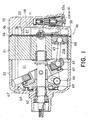
- the illustrated compressor 50 comprises a cylinder block 51, a front housing 52 arranged on one side of the cylinder block 51, and a rear housing 53 arranged on the opposite side of the cylinder block 51.
- a valve plate 54 is interposed between the cylinder block 51 and the rear housing 53.
- the cylinder block 51 and the front housing 52 have through holes communicated with each other at the center thereof, which together form one through hole.
- a main shaft 62 is inserted into this through hole and rotatably supported by the front housing 52 and the cylinder block 51.
- the front housing 52 defines a crank chamber 61 in cooperation with the cylinder block 51.
- a rotor 65 is mounted on the main shaft 62.
- a swash plate 60 is coupled to the rotor 65 via a hinge mechanism including a guide pin 66.
- the main shaft 62 passes through the swash plate 60 such that the swash plate 60 abuts on the main shaft 62 at the inside thereof so as to rotate together with the main shaft 62.
- An inclination of the swash plate 60 relative to the main shaft 62 can be changed by means of the hinge mechanism.
- a wobble plate 63 is slidablely mounted on the swash plate 60 via bearings 67.
- a plurality of cylinders 51a are arranged at regular angular intervals so as to surround the main shaft 62.
- a plurality of piston rods 69 are coupled to the wobble plate 63 through ball connection. Furthermore, each of piston rods 69 is coupled through ball connection to corresponding one of pistons 68 disposed in the respective cylinders 51a.
- a discharge chamber 57 and a suction chamber 58 are formed by inner, outer and bottom walls 55, 56 and 118 of the rear housing 53, and the valve plate 54.
- the bottom walls 118 also defines an accommodating room 53a adapted to accommodate a displacement control valve 100 (or 10).
- the accommodating room 53a itself communicates with the discharge chamber 57 and the suction chamber 58 via through holes, and also does with the crank chamber 61 via a communication passage 71.
- an existing displacement control valve 100 comprises a valve casing 101 and a cap member 102 arranged on one side of the valve casing 101 and covering it.
- the one side of the valve casing 101 caves in to form a room 104 together with the cap member 102, where a bellows 112 is disposed.
- the other side of the valve casing 101 caves in to define a valve cavity 103.
- Such displacement control valve 100 is accommodated in the accommodating room 53a with a part of the valve casing 101 exposed in a space 117.
- the space 117 is applied with gas pressure of the discharge chamber 57 through a hole 116, and thereby, the valve cavity 103 is also applied with gas pressure of the discharge chamber 57.
- a through hole 105 is formed between the room 104 and the valve cavity 103, and extends in an up-to-down direction in the figure.
- the valve casing further has another through hole 106 extending in a direction perpendicular to the up-to-down direction, the through hole 106 communicating the hole 105 with a surrounding area 109 of the valve casing 101.
- the hole 106 and a part of the hole 105 comprise a part of the communication passage 71.
- a ball valve 107 is arranged on the communication passage 71 and downwardly biased by a spiral spring 108.
- the valve 107 receives a downward force in Fig. 2, which is due to bias of the spiral spring 108 and gas pressure of the discharge chamber 57.
- the downward force serves to move the ball valve 107 in downward sense where the communication passage 71 will be closed, and therefore, such downward force will be referred to as the closing force F v hereinafter.
- the bellows 102 is mounted on an adjusting screw 113, and is connected to a rod 114 via a supporting member 111.
- the room 104 is communicated with the suction chamber 58 via the through hole 115 so that the bellows 112 can sense gas pressure of the suction chamber 58 and expands/contracts itself in response to the gas pressure of the suction chamber 58.
- an internal spring 112a is placed and makes a force corresponding to the gas pressure of the suction chamber 58, together with the bellows 112.
- the force is transferred to the ball valve 107 by the rod 114.
- the ball valve 107 receives gas pressure of the crank chamber 61 on a sealing area of the ball valve 107, which seals the communication passage 71.
- the pressure of the crank chamber 61 and the transferred force comprises an upward force serving to move the ball valve 107 in an upward sense where the communication passage 71 is opened, and therefore, such upward force will be called the opening force F b hereinafter.
- This Inequality (4) represents a characteristic of controlling gas pressure in the suction chamber 58, which belongs to the displacement control valve 100. As a graph of the characteristic depicted in Fig. 3, gas pressure of the suction chamber 58 varies, depending upon gas pressure of the discharge chamber 57.
- a bottom level of the internal spring 112a is determined so that the force f b can be adjusted to f b1 , f b2 , and f b3 , as shown in Fig. 4. That is, the adjusting screw 113 can change an intercept of the characteristic in the figure.
- the displacement control valve should be modified drastically in its structure. Such drastic modification gives a harmful influence on its design, and therefore is undesirable.
- the sealing area of the ball valve 107 is changed, the amount of gas introduced from the discharge chamber 57 into the crank chamber 61 is also changed so that a starting characteristic of gas pressure in the crank chamber 61 fluctuates. Such fluctuation makes the characteristic of controlling gas pressure in the suction chamber 58 unstable.
- a displacement control valve can easily change the characteristic of controlling gas pressure in the suction chamber 58 with no change of the sealing area of the valve member and the effective area of the bellows.
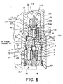
- a displacement control valve 10 is for use in a variable displacement compressor having a discharge chamber 57, a suction chamber 58, and a crank chamber 61.
- the illustrated valve 10 is arranged within the accommodating room 53a of the rear housing 53, and comprises a main portion 1, a first cap member 2 and a second cap member 14 which are assembled into a valve casing (1, 2, 14).
- a space 26 is communicated with the discharge chamber 57 via a through hole 27 to be introduced gas pressure of the discharge chamber 57 thereinto.
- the second cap member 14 and a part of the main portion 1 are exposed to be applied with gas pressure of the chamber 57.
- the first cap member 2 is applied with gas pressure of the suction chamber 58 via a through hole 15.
- the main portion 1 of the valve casing has opposite sides of the longitude direction thereof, each of which caves in.
- One side of the main portion 1 defines a sensing room 4 together with the first cap member 2, where a bellows 7 is disposed.
- the first cap member 2 has a through hole 2a between the sensing room 4 and a periphery of the first cap member 2 so that the sensing room 4 is applied with gas pressure of the suction chamber 58.
- the other side of main portion 1 defines a valve cavity 16 together with a valve guide 13, and furthermore, does a pressure room 17 together with the second cap member 14.
- the illustrated valve guide 13 has a co-axial shape and has a through hole 13a extending in a longitude direction of the valve casing. Between the valve cavity 16 and the sensing room 4, a through hole 11 is also formed.
- the main portion 1 has the hollow surrounding thereof so that the hollow of the main portion 1 defines a room 22 together with the accommodating room 53a when the displacement control valve 10 is arranged within the accommodating room 53a.
- the main part 1 of the valve casing has a through hole 25 formed between the space 26 and the valve cavity 16, and through holes 23, 24 formed between a part of the through hole 11 and the room 22.
- the through holes 27, 25, 23 and 24, a part of the through hole 11, parts of the rooms 26 and 22, and the valve cavity 16 comprise a communication passage 71. That is, the main portion 1 of the valve casing defines a communication passage 71 which is to communicate the discharge chamber 57 with the crank chamber 61 and which the valve cavity 16 is included within (or arranged on the way of).
- Such communication passage 71 serves to conduct gas from the discharge chamber 57 to the crank chamber 61 in cooperation with a valve member 15, that will be mentioned in detail, later.
- the valve member 15 has a shape extending in a longitude direction of the valve casing, and has first and second surface 15a and 15b opposite to each other in the direction. Such valve member 15 is placed on the through hole 11 in the valve cavity 16, and is partially and movably held in the through hole 13a of the valve guide 13. Under the circumstances, the valve member 15 is slidable in the longitude direction, depending upon forces which are applied on the first and the second surfaces 15a and 15b of the valve member 15.
- the valve member 15 has a part 15c of large cross section in a plane perpendicular to the longitude direction, while the valve cavity 16 has a valve seat 31 facing the first surface 15a of the valve member 15 on the through hole 11.
- the communication passage 71 is closed when the valve member 15 rests on the valve seat 31 and, on the other hand, the communication passage 71 is opened when the valve member 15 is apart from the valve seat 31. That is, the valve member 15 can adjust a substantial opening degree of the communication passage 71, by the movement thereof. Such movement of the valve member 15 is mentioned in detail below.
- the main portion 1 of the valve casing further defines an additional communication passage 28, such as a through hole, formed between the through hole 24 and the pressure room 17.
- the valve member 15 receives, on the first surface 15a thereof, gas pressure of the crank chamber 61 through the communication passage 71.
- the additional communication passage 28 serves to also apply with the gas pressure of the crank chamber 61 to the second surface 15b.
- the first surface 15a has a first area which receives the gas pressure of the chamber 61 thereon when the valve member 15 rests on the valve seat 31, while the second surface 15b has a second area which is subjected to the gas pressure of the chamber 61 when the valve member 15 rests on the valve seat 31.
- the first and second areas are equal to each other.
- the part 15c of the valve member 15 has a constant cross section so as not to be given the influence of the gas pressure of the discharge chamber 57.
- the gas pressure of the crank chamber 61 acting onto the first surface 15a is canceled with that applied to the second surface 15b. Therefore, the movement of the valve member 15 itself is independent from the gas pressure of the crank chamber 61.
- the bellows 7 is placed within the sensing room 4, as mentioned above. More in detail, the bellows 7 is mounted on an adjusting screw 8 in the sensing room 4, and is connected to a rod 12 via a supporting member 6. Since the sensing room 4 is communicated with the suction chamber 58, the bellows 7 can sense gas pressure of the chamber 58 to expand/contract in response to the gas pressure of the chamber 58.
- an internal spring 9 is placed and makes a force corresponding to gas pressure of the suction chamber 58, together with the bellows 7.
- the force is transmitted via the rod 12 onto the first surface 15a of the valve member 15.
- the influence of gas pressure of the chamber 61 onto the first surface 15a of the valve member 15, is prevented by the additional communication passage 28, as described above. Therefore, only the transmitted force by the rod 12 substantially operates upon the fist surface to move or drive the valve member 15. That is, the transmitted force is the opening force F b of the valve mechanism 10 and, in this connection, the supporting member 6, the bellows 7, the internal spring 9, and the rod 12 together serve as a driving member for driving the valve member 15 to opening of the communication passage 71.
- the second cap member 14 has a through hole 14a formed between the space 26 and the pressure room 17 and sliderably holds a sensing rod 21 in the through hole 14a thereof.
- the sensing rod 21 extends along the longitude direction of the valve casing, and has first and second pressure sensing areas 21a and 21b.
- the first sensing area 21a projects over the space 26 and receives the gas pressure of the discharge chamber 57
- the second pressure sensing area 21b is arranged within the pressure room 17 and receives the gas pressure of the crank chamber 61.
- the sensing rod 21 serves to produce a force corresponding to difference between the gas pressure of the discharge chamber 57 and the gas pressure of the crank chamber 61.
- the produced force is determined in dependent on cross section of the sensing rod 21 in a plane perpendicular to the longitude direction of the valve casing. That is, the first and the second pressure sensing area 21a and 21b of the sensing rod 21 are equal to each other in this embodiment.
- the produced force is transmitted via a transmission member into the second surface 15b of the valve member 15.
- the transmission member does only transmit the produced force under the circumstances the produced force is downward force, besides, the valve member 15 itself does not depend upon the influence of the gas pressure. Therefore, the produced force is the closing force F v and, in this connection, the sensing rod 21, the spring 19, and the spring guides 18a, 18b together serve a driving member for driving the valve member 15 to closing of the communication passage 71.
- the illustrated transmission member comprises an elastic member, such as a spring 19, and guide members, such as spring guides 18a, 18b.
- Such transmission member is disposed between the sensing rod 21 and the second surface 15b of the valve member 15, namely, is arranged within the pressure room 17.
- the sensing rod 21, the spring 19, and the valve member 15 are arranged on an axis extending in the longitude direction of the valve casing in this embodiment.
- This Inequality (8) represents a characteristic of controlling gas pressure in the suction chamber 58, which belongs to the displacement control valve 10.
- the change ratio of the gas pressure of the suction chamber 58 to the gas pressure of the discharge chamber 57 can be varied with no change the sealing area S v of the valve member 15 and/or the effective area S b of the bellows 7.
- the characteristic depicted in Fig. 6 has a flat part.
- the flat part of the characteristic shows that, when the pressure of the discharge chamber 57 becomes lower than a certain value which produces upward force of the sensing rod 21, the characteristic is subjected to no influence of the pressure of the discharge chamber 57, because elastic force of the spring 19 is larger than the force due to the sensing rod 21, and thereby, the spring guide 18b has contact with the second cap member 14 to stop the extension of the spring 19.
Landscapes
- Engineering & Computer Science (AREA)
- Mechanical Engineering (AREA)
- General Engineering & Computer Science (AREA)
- Compressors, Vaccum Pumps And Other Relevant Systems (AREA)
- Fluid-Driven Valves (AREA)
Applications Claiming Priority (2)
| Application Number | Priority Date | Filing Date | Title |
|---|---|---|---|
| JP17118098 | 1998-06-18 | ||
| JP10171180A JP2000009033A (ja) | 1998-06-18 | 1998-06-18 | 可変容量圧縮機の容量制御弁機構 |
Publications (2)
| Publication Number | Publication Date |
|---|---|
| EP0965754A2 true EP0965754A2 (de) | 1999-12-22 |
| EP0965754A3 EP0965754A3 (de) | 2000-02-02 |
Family
ID=15918495
Family Applications (1)
| Application Number | Title | Priority Date | Filing Date |
|---|---|---|---|
| EP99111736A Ceased EP0965754A3 (de) | 1998-06-18 | 1999-06-17 | Ventil zur Hubregelung zur Verwendung in einem Kompressor mit veränderlicher Verdrängung |
Country Status (2)
| Country | Link |
|---|---|
| EP (1) | EP0965754A3 (de) |
| JP (1) | JP2000009033A (de) |
Families Citing this family (2)
| Publication number | Priority date | Publication date | Assignee | Title |
|---|---|---|---|---|
| JP4644475B2 (ja) * | 2004-11-30 | 2011-03-02 | 株式会社不二工機 | 圧力調整弁 |
| JP2007138785A (ja) | 2005-11-16 | 2007-06-07 | Toyota Industries Corp | 車両用冷凍回路の制御装置、容量可変型圧縮機及び容量可変型圧縮機用制御弁 |
Family Cites Families (8)
| Publication number | Priority date | Publication date | Assignee | Title |
|---|---|---|---|---|
| JP2567947B2 (ja) * | 1989-06-16 | 1996-12-25 | 株式会社豊田自動織機製作所 | 可変容量圧縮機 |
| KR910004933A (ko) * | 1989-08-09 | 1991-03-29 | 미다 가쓰시게 | 가변용량사판식 압축기 |
| SG30647G (en) * | 1991-01-28 | 1995-09-01 | Sanden Corp | Slant plate type compressor with variable displacement mechanism |
| JP3178631B2 (ja) * | 1993-01-11 | 2001-06-25 | 株式会社豊田自動織機製作所 | 可変容量型圧縮機用制御弁 |
| JP3355002B2 (ja) * | 1993-10-15 | 2002-12-09 | 株式会社豊田自動織機 | 可変容量型圧縮機用制御弁 |
| JP3255008B2 (ja) * | 1996-04-17 | 2002-02-12 | 株式会社豊田自動織機 | 可変容量圧縮機及びその制御方法 |
| JP3585150B2 (ja) * | 1997-01-21 | 2004-11-04 | 株式会社豊田自動織機 | 可変容量圧縮機用制御弁 |
| JP3754193B2 (ja) * | 1997-10-03 | 2006-03-08 | サンデン株式会社 | 可変容量圧縮機の容量制御弁 |
-
1998
- 1998-06-18 JP JP10171180A patent/JP2000009033A/ja not_active Withdrawn
-
1999
- 1999-06-17 EP EP99111736A patent/EP0965754A3/de not_active Ceased
Non-Patent Citations (1)
| Title |
|---|
| None |
Also Published As
| Publication number | Publication date |
|---|---|
| JP2000009033A (ja) | 2000-01-11 |
| EP0965754A3 (de) | 2000-02-02 |
Similar Documents
| Publication | Publication Date | Title |
|---|---|---|
| JP3131036B2 (ja) | 電磁式比例制御弁 | |
| JP3355002B2 (ja) | 可変容量型圧縮機用制御弁 | |
| US6485267B1 (en) | Control valve for variable capacity compressors | |
| JP3088536B2 (ja) | 可変容量型揺動式圧縮機 | |
| US20020182087A1 (en) | Control valve for variable capacity compressors | |
| US4778348A (en) | Slant plate type compressor with variable displacement mechanism | |
| US6196808B1 (en) | Variable displacement compressor and displacement control valve system for use therein | |
| KR100443158B1 (ko) | 벨로스식 압력 응동밸브 | |
| JPS62276279A (ja) | 冷凍システム | |
| JPH11351140A (ja) | 可変容量圧縮機の容量制御弁機構 | |
| EP0519598B1 (de) | Schiefscheibenverdichter mit Vorrichtung zur Hubveränderung | |
| EP0945617A2 (de) | Kontrollventil zur Kapazitätseinstellung eines Verstellkompressors | |
| JPH10141219A (ja) | 可変容量圧縮機 | |
| JP4436295B2 (ja) | 可変容量圧縮機 | |
| US4850810A (en) | Slant plate type compressor with variable displacement mechanism | |
| US20060039798A1 (en) | Control valve for variable displacement compressor | |
| JPH10205443A (ja) | 可変容量圧縮機 | |
| JP2017180293A (ja) | 両頭ピストン型斜板式圧縮機 | |
| JP2616511B2 (ja) | 可変容量型揺動斜板式圧縮機における容量制御弁 | |
| KR20010079737A (ko) | 용량가변형 압축기용 제어밸브 | |
| JP3082485B2 (ja) | 揺動斜板式可変容量圧縮機 | |
| JP2000009033A (ja) | 可変容量圧縮機の容量制御弁機構 | |
| EP0908624A2 (de) | Ventil zur Hubregelung zur Verwendung in einem Kompressor mit veränderlicher Verdrängung | |
| EP0896154A2 (de) | Kompressor mit variabler Fördermenge mit einem im Bezug auf einer Montageposition des Kompressors verbesserten Verbindungsdurchgang zwischen einem Kurbelgehäuse und einer Saugkammer | |
| JP4329053B2 (ja) | 可変容量型斜板式圧縮機 |
Legal Events
| Date | Code | Title | Description |
|---|---|---|---|
| PUAI | Public reference made under article 153(3) epc to a published international application that has entered the european phase |
Free format text: ORIGINAL CODE: 0009012 |
|
| PUAL | Search report despatched |
Free format text: ORIGINAL CODE: 0009013 |
|
| AK | Designated contracting states |
Kind code of ref document: A2 Designated state(s): DE FR |
|
| AX | Request for extension of the european patent |
Free format text: AL;LT;LV;MK;RO;SI |
|
| AK | Designated contracting states |
Kind code of ref document: A3 Designated state(s): AT BE CH CY DE DK ES FI FR GB GR IE IT LI LU MC NL PT SE |
|
| AX | Request for extension of the european patent |
Free format text: AL;LT;LV;MK;RO;SI |
|
| 17P | Request for examination filed |
Effective date: 20000316 |
|
| 17Q | First examination report despatched |
Effective date: 20000516 |
|
| AKX | Designation fees paid |
Free format text: DE FR |
|
| GRAG | Despatch of communication of intention to grant |
Free format text: ORIGINAL CODE: EPIDOS AGRA |
|
| STAA | Information on the status of an ep patent application or granted ep patent |
Free format text: STATUS: THE APPLICATION HAS BEEN REFUSED |
|
| 18R | Application refused |
Effective date: 20010524 |