EP0965775B1 - Dispositif et procédé de contrôle d'une transmission à variation de vitesse continue - Google Patents
Dispositif et procédé de contrôle d'une transmission à variation de vitesse continue Download PDFInfo
- Publication number
- EP0965775B1 EP0965775B1 EP99111431A EP99111431A EP0965775B1 EP 0965775 B1 EP0965775 B1 EP 0965775B1 EP 99111431 A EP99111431 A EP 99111431A EP 99111431 A EP99111431 A EP 99111431A EP 0965775 B1 EP0965775 B1 EP 0965775B1
- Authority
- EP
- European Patent Office
- Prior art keywords
- final target
- speed
- speed ratio
- input rotation
- rotation speed
- Prior art date
- Legal status (The legal status is an assumption and is not a legal conclusion. Google has not performed a legal analysis and makes no representation as to the accuracy of the status listed.)
- Expired - Lifetime
Links
- 238000000034 method Methods 0.000 title claims description 21
- 230000005540 biological transmission Effects 0.000 title claims description 16
- 230000001052 transient effect Effects 0.000 claims description 17
- 230000001133 acceleration Effects 0.000 description 22
- 230000000994 depressogenic effect Effects 0.000 description 5
- 238000010586 diagram Methods 0.000 description 3
- 230000008447 perception Effects 0.000 description 3
- 230000003247 decreasing effect Effects 0.000 description 2
- 230000007423 decrease Effects 0.000 description 1
- 230000000694 effects Effects 0.000 description 1
- 239000000446 fuel Substances 0.000 description 1
- 239000000203 mixture Substances 0.000 description 1
- 230000000717 retained effect Effects 0.000 description 1
Images


Classifications
-
- F—MECHANICAL ENGINEERING; LIGHTING; HEATING; WEAPONS; BLASTING
- F16—ENGINEERING ELEMENTS AND UNITS; GENERAL MEASURES FOR PRODUCING AND MAINTAINING EFFECTIVE FUNCTIONING OF MACHINES OR INSTALLATIONS; THERMAL INSULATION IN GENERAL
- F16H—GEARING
- F16H61/00—Control functions within control units of change-speed- or reversing-gearings for conveying rotary motion ; Control of exclusively fluid gearing, friction gearing, gearings with endless flexible members or other particular types of gearing
- F16H61/66—Control functions within control units of change-speed- or reversing-gearings for conveying rotary motion ; Control of exclusively fluid gearing, friction gearing, gearings with endless flexible members or other particular types of gearing specially adapted for continuously variable gearings
- F16H61/662—Control functions within control units of change-speed- or reversing-gearings for conveying rotary motion ; Control of exclusively fluid gearing, friction gearing, gearings with endless flexible members or other particular types of gearing specially adapted for continuously variable gearings with endless flexible members
- F16H61/66254—Control functions within control units of change-speed- or reversing-gearings for conveying rotary motion ; Control of exclusively fluid gearing, friction gearing, gearings with endless flexible members or other particular types of gearing specially adapted for continuously variable gearings with endless flexible members controlling of shifting being influenced by a signal derived from the engine and the main coupling
Definitions
- the invention relates to a speed ratio controller and to a speed ratio control method having the features of the preamble portions of claims 1 and 8.
- a controller and such a method are known from US 5,319,999.
- a continuously variable transmission (CVT)
- the variation of speed ratio when an accelerator pedal is fully depressed is set for example as follows.
- the speed ratio is changed to a maximum value, i.e., the speed ratio at which an output rotation speed is lowest relative to an input rotation speed.
- the engine rotation speed is increased to a maximum region, and a running speed is then increased by decreasing the speed ratio.
- the engine rotation speed remains in the maximum region for a long period from when the accelerator pedal is depressed to when the vehicle speed reaches the speed desired by the driver, and this causes a large noise outside the vehicle.
- Tokkai Hei 5-126239 published by the Japanese Patent Office in 1993 discloses a method wherein a transient target speed ratio is set so that the engine rotation speed increases gradually for a sudden operation of the accelerator pedal.
- the engine rotation speed increases gradually due to the fact that the speed ratio changes to the maximum value comparatively slowly.
- the time during which the engine rotation speed is in the maximum region is short, so vehicle noise due to acceleration is less.
- a rotation output of a vehicle engine 1 is input into a V-belt continuously variable transmission 2 via a torque converter 6.
- the engine 1 is provided with a throttle 3 which opens and closes according to an operation of an accelerator pedal by a driver, and a mixture of air aspirated via the throttle 3 and fuel injected into the air is burnt to run the vehicle.
- a V-belt 9 is looped around a primary pulley 7 joined to the output shaft of the engine 1 via the torque converter 6, and a secondary pulley 8.
- the secondary pulley 8 rotates drive wheels, not shown, via a final drive gear set 10 and differential gear set 11.
- the primary pulley 7 and secondary pulley 8 each comprise a V-shaped groove for looping the belt.
- grooves expand and contract according to oil pressures Ppri, Psec supplied from an actuator 12, and a speed ratio is varied by varying the contact radii of the V belt and pulleys according to the variation of groove width.
- This speed ratio is controlled from a controller 13 according to a target speed ratio RTO output to the actuator 12 as a signal.
- the controller 13 is a microcomputer comprising a central processing unit (CPU), read-only memory (RAM), random access memory (ROM) and input/output interface (I/O interface).
- CPU central processing unit
- RAM read-only memory
- ROM random access memory
- I/O interface input/output interface
- signals are input to the controller 13 respectively from a throttle opening sensor 16 which detects a throttle opening TVO , a rotation speed sensor 18 which detects a rotation speed No of the secondary pulley 8, a vehicle speed sensor 19 which detects a vehicle speed VSP , and a mode sensor 20 which detects a vehicle running mode selected by a selector lever.
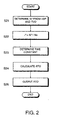
- the controller 13 calculates the target speed ratio RTO by the main routine shown in Fig. 2 based on these input signals.
- This routine is performed, for example, at an interval of 10 milliseconds.
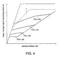
- a final target input rotating speed Ni* which the continuously variable transmission 2 should finally reach is found from the vehicle speed VSP and throttle opening TVO by referring to a map shown in Fig. 4. This map will be described in detail later.
- a final target speed ratio i* is computed by dividing the final target input rotating speed Ni* by a transmission output rotation speed No.
- a time constant of the speed ratio variation is determined.
- the time constant is determined according to a deviation between a transient target speed ratio RTO -1 calculated on the immediately preceding occasion when the routine was performed and the final target ratio i* based on a final input rotation speed for normal running which will be described later.
- the method of determining the time constant is known from the aforesaid prior art Tokkai Hei 5-126239.
- a step S24 the transient target speed ratio RTO for achieving the final speed ratio i* under the time constant of the speed ratio variation determined in the step S24 is computed.
- a signal corresponding to the transient target speed ratio RTO is output to the actuator 12, and the routine is terminated.
- the final target input rotation speed for acceleration is obtained by applying a limit to the final target input rotation speed Ni* for normal running so that the noise level outside the vehicle is within a permitted level.
- This upper limiting value is set to, for example, 5,600 rpm.
- step S23 the final input rotation speed for normal running is always applied.
- step S21 two maps are selectively applied.
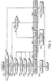
- This process is a sub-routine of the main routine of Fig. 2 described above.
- the subroutine is performed at the same 10 milliseconds interval as the main routine.
- step S31 the controller 13 determines whether or not the vehicle running mode selected by the selector lever is an automatic speed change mode (D).
- a mode other than the mode (D) is chosen, in a step S32, the final target input rotating speed map for normal running shown by the solid line of Fig. 4 is selected.
- the selected map is used for the calculation of final target input rotating speed in the step S21 when the main routine of Fig. 2 is next performed.
- a vehicle start flag FLAG ACC is reset to 0, and the subroutine is terminated.
- the subroutine proceeds to a step S34.
- the vehicle start flag FLAG ACC set on the immediately preceding occasion when the subroutine was performed is 0.
- the throttle opening TVO is equal to or greater than a set opening TVO S .
- the set opening TVO S may, for example, be 4/8, where 8/8 denotes full throttle opening.
- the routine proceeds to a step S36, and it is determined whether or not the vehicle speed VSP is equal to or higher than a set vehicle speed VSP S .
- the set vehicle speed VSP S is set to, for example, 30km/hour.
- the routine proceeds to a step S37, and it is determined whether or not the final target speed ratio i* is equal to or greater than a set final target speed ratio i S * , i.e., whether or not the final target speed ratio i* gives a lower vehicle speed than the set final target speed ratio i S * .
- the set final target speed ratio i S * is set to, for example, 1.8.
- the routine proceeds to a step S38, and it is determined whether or not the transient target speed ratio RTO is equal to or greater than a set value RTO S , i.e., whether or not the transient target speed ratio RTO gives a lower vehicle speed than the set value RTO S .
- the set value RTO S is set to, for example, 1.8.
- step S38 when the transient target speed ratio RTO is equal to or greater than the set value RTO S , it is determined that the vehicle is accelerating during startup.
- the map of final target input rotating speed for normal running i.e., the map shown by the solid line of Fig. 4, is selected in a step S39. Due to this, in the step S21 of the main routine, the calculation of the final target input rotating speed Ni* is performed using the map of final target input rotating speed for normal running.
- step S40 the vehicle start flag FLAG ACC is set to 1, and the subroutine is terminated.
- the map of final target input rotation speed for acceleration gives a different value from the map of final target input rotation speed for normal running only when the throttle opening TVO is equal to or greater than the set opening TVO S , and the vehicle speed VSP is equal to or higher than the set vehicle speed VSP S .
- the map of final target input rotation speed for acceleration is chosen in the step S45 even when the vehicle is accelerating under a small throttle opening TVO after starting.
- the map of final target input rotation speed for acceleration supplies the same final target input rotation speed Ni* as the map of final target input rotation speed for normal running, so there is no effect on the transient target speed ratio RTO calculated in the main routine, and ordinary speed ratio control is in fact performed. This is the same as when proceeding to the step S45 from the step S37 or step S38.
- step S45 selecting the map of final target input rotation speed for acceleration is meaningful. This will be described in detail later.
- step S41 it is determined whether or not the throttle opening TVO is larger than the set opening TVO S .
- a step S42 as in the step S39, the map of final target input rotation speed for normal running is selected, the vehicle start flag FLAG ACC is retained at its current value in a step S43, and the process is terminated.
- step S41 when it is determined that the throttle opening TVO is less than the set opening TVO S , it means that the accelerator pedal depression amount has decreased from the state when the vehicle was accelerating for vehicle startup, i.e., the vehicle speed has been stabilized.
- the process proceeds to a step S44, the map of final target input rotation speed for acceleration is selected, the vehicle start flag FLAG ACC is reset to 0 in the step S33, and the process is terminated.
- speed ratio control in this case effectively uses the same map as that used for speed ratio control in the normal state.
- the routine proceeds to a step S45, and the map of final target input rotation speed for acceleration is selected.
- the actual speed characteristics are not different from the case where the map of final target input rotation speed for normal running is selected, as described hereabove.
- the subroutine is terminated in the following step S43 while the vehicle start flag FLAG ACC is maintained at 0.
- the vehicle speed VSP is higher than the set vehicle speed VSP S in the following step S36.
- the map of final target input rotation speed for acceleration is selected. This case is a case where the vehicle is not accelerated from rest, while the accelerator pedal is largely depressed and the vehicle is running at or above the set vehicle speed VSP S .
- the final target input rotation speed Ni* is limited to the upper limiting value ⁇ .
- the calculation of the time constant of the speed ratio variation in the step S23 is performed using the final target ratio i* for normal running.
- the noise can be suppressed to or less than a permitted level ⁇ , as shown by the curve ⁇ in Fig. 5B.
- a period ⁇ t 1 until the final target speed ratio i* is attained is longer than a period ⁇ t 0 until the final target speed ratio i* is attained when the final target input rotation speed Ni* is not limited, and the feeling of acceleration is lost.
- the period required for the speed change can be set to the same period ⁇ t 0 as in the case where no limit is applied to the final target input rotation speed Ni* , while at the same time suppressing the noise outside the vehicle to or below the permitted level y as shown by the curve ⁇ .
- the final target input rotation speed for normal running corresponds to a first final target input rotation speed
- the final target input rotation speed for acceleration corresponds to a second final target input rotation speed
- This invention was described in the context of its application to a speed ratio control of a belt-type continuously variable transmission, but it may be applied also to a toroidal type continuously variable transmission.
Landscapes
- Engineering & Computer Science (AREA)
- General Engineering & Computer Science (AREA)
- Mechanical Engineering (AREA)
- Control Of Transmission Device (AREA)
Claims (8)
- Dispositif de commande du rapport de transmission pour utilisation avec un véhicule qui roule sous une force d'entraínement d'un moteur (1) par une transmission variable en continu, ledit dispositif de commande comprenant :caractérisé parun capteur (16, 20) pour détecter un état de roulement dudit véhicule,un capteur (19) pour détecter une vitesse du véhicule,des moyens (S32, S39, S42) pour calculer une première vitesse de rotation d'entrée recherchée finale de ladite transmission variable en continu (2) sur la base dudit état de roulement,des moyens (S44, S45) pour calculer une seconde vitesse de rotation d'entrée recherchée finale en limitant une limite supérieure de ladite première vitesse de rotation d'entrée recherchée finale avec une valeur prédéterminée,
un moyen (S22) pour calculer un second rapport de transmission recherché final à partir de ladite vitesse du véhicule et une seconde vitesse de rotation d'entrée recherchée finale,
un moyen (S23) pour calculer un premier rapport de transmission recherché final à partir de ladite vitesse du véhicule et la première vitesse de rotation d'entrée recherchée finale,
un moyen (S23) pour calculer une constante de temps d'une variation du rapport de transmission sur la base de ladite première vitesse de rotation d'entrée recherchée finale,
un moyen (S24) pour établir un rapport de transmission recherché transitoire à partir dudit second rapport de transmission recherché final et ladite constante de temps et
un moyen (S25) pour commander un rapport de transmission de ladite transmission variable en continu pour qu'il soit égal audit rapport de transmission recherché transitoire. - Dispositif de commande du rapport de transmission selon la revendication 1, où le premier moyen de calcul de vitesse de rotation d'entrée recherchée finale (S32, S39, S42), le second moyen de calcul de vitesse de rotation d'entrée recherché final (S44, S45), le second moyen de calcul de rapport de transmission recherché final (S22), le premier moyen de calcul de rapport de transmission recherché final (S23), le moyen de calcul de constante de temps (S23), le moyen d'établissement du rapport de transmission recherché transitoire (S24) et le moyen de commande du rapport de transmission (S25) sont réalisés sous la forme d'un micro-processeur (13) programmé pour :calculer ladite première vitesse de rotation d'entrée recherchée finale de ladite transmission variable en continu (2) sur la base dudit état de roulement (S32, S39, S42),calculer ladite seconde vitesse de rotation d'entrée recherchée finale en limitant la limite supérieure de ladite première vitesse de rotation d'entrée recherchée finale avec la valeur prédéterminée (S44, S45),calculer ledit second rapport de transmission recherché final à partir de ladite vitesse du véhicule et de la seconde vitesse de rotation d'entrée recherchée finale (S22),calculer ledit premier rapport de transmission recherché final à partir de ladite vitesse du véhicule et la première vitesse de rotation d'entrée recherchée finale (S23),calculer ladite constante de temps de la variation du rapport de transmission sur la base de ladite première vitesse de rotation d'entrée recherchée finale (S23),établir ledit rapport de transmission recherché transitoire à partir dudit second rapport de transmission recherché final et ladite constante de temps (S24) etcommander ledit rapport de transmission de ladite transmission variable en continu (2) pour qu'il soit égal audit rapport de transmission recherché transitoire (S25).
- Dispositif de commande du rapport de transmission selon la revendication 2, où ledit micro-processeur (13) est programmé pour répéter la commande du rapport de transmission à un intervalle prédéterminé et pour calculer ladite constante de temps sur la base d'un écart entre ledit premier rapport de transmission recherché calculé à une occasion présente et ledit rapport de transmission recherché transitoire calculé à une occasion directement précédente lorsque la commande du rapport de transmission a été exécutée.
- Dispositif de commande du rapport de transmission selon la revendication 2, où ledit capteur de détection de l'état de roulement (16, 19) comprend un capteur (19) pour détecter ladite vitesse de véhicule, et un capteur (16) pour détecter une ouverture du papillon dudit moteur (1).
- Dispositif de commande du rapport de transmission selon la revendication 4, où ledit micro-processeur (13) est programmé pour établir ladite seconde vitesse de rotation d'entrée recherchée finale pour qu'elle soit égale à ladite première vitesse de rotation d'entrée recherchée finale lorsque ladite ouverture du papillon est plus petite qu'une ouverture prédéterminée.
- Dispositif de commande du rapport de transmission selon la revendication 4, où ledit micro-processeur (13) est programmé pour établir ladite seconde vitesse de rotation d'entrée recherchée finale pour qu'elle soit égale à ladite première vitesse de rotation d'entrée recherchée finale lorsque ladite vitesse du véhicule est inférieure à une vitesse prédéterminée.
- Dispositif de commande du rapport de transmission selon la revendication 2, où ladite valeur prédéterminée est établie sur la base d'un niveau de bruit à l'extérieur du véhicule produit par ledit moteur (1).
- Procédé de commande du rapport de transmission pour un véhicule qui roule sous une force d'entraínement d'un moteur (1) par une transmission variable en continu (2), ledit procédé comprenant :caractérisé parla détection d'un état de roulement dudit véhicule,la détection d'une vitesse du véhicule,le calcul d'une première vitesse de rotation d'entrée recherchée finale de ladite transmission variable en continu (2) sur la base dudit état de roulement (S32, S39, S42),le calcul d'une seconde vitesse de rotation d'entrée recherchée finale en limitant une limite supérieure de ladite première vitesse de rotation d'entrée recherchée finale par une valeur prédéterminée (S44, S45),
calculer un second rapport de transmission recherché final à partir de ladite vitesse du véhicule et la seconde vitesse de rotation d'entrée recherchée finale (S22),
calculer un premier rapport de transmission recherché final à partir de ladite vitesse du véhicule et de la première vitesse de rotation d'entrée recherchée finale (S23),
calculer une constante de temps d'une variation du rapport de transmission sur la base de ladite première vitesse de rotation d'entrée recherchée finale (S23),
établir un rapport de vitesse recherché transitoire à partir dudit second rapport de transmission recherché final et de ladite constante de temps (S24) et
commander le rapport de transmission de ladite transmission variable en continu pour qu'il soit égal audit rapport de transmission recherché transitoire (S25).
Applications Claiming Priority (4)
| Application Number | Priority Date | Filing Date | Title |
|---|---|---|---|
| JP16685598 | 1998-06-15 | ||
| JP16685598 | 1998-06-15 | ||
| JP15728699A JP3855536B2 (ja) | 1998-06-15 | 1999-06-04 | 無段変速機の変速制御装置 |
| JP15728699 | 1999-06-04 |
Publications (3)
| Publication Number | Publication Date |
|---|---|
| EP0965775A2 EP0965775A2 (fr) | 1999-12-22 |
| EP0965775A3 EP0965775A3 (fr) | 2000-08-16 |
| EP0965775B1 true EP0965775B1 (fr) | 2003-10-08 |
Family
ID=26484793
Family Applications (1)
| Application Number | Title | Priority Date | Filing Date |
|---|---|---|---|
| EP99111431A Expired - Lifetime EP0965775B1 (fr) | 1998-06-15 | 1999-06-11 | Dispositif et procédé de contrôle d'une transmission à variation de vitesse continue |
Country Status (4)
| Country | Link |
|---|---|
| US (1) | US6174261B1 (fr) |
| EP (1) | EP0965775B1 (fr) |
| JP (1) | JP3855536B2 (fr) |
| DE (1) | DE69911851T2 (fr) |
Families Citing this family (15)
| Publication number | Priority date | Publication date | Assignee | Title |
|---|---|---|---|---|
| EP1010920A3 (fr) * | 1998-12-15 | 2001-09-12 | Nissan Motor Co., Ltd. | Dispositif et procédé de commande du rapport d'engrenage pour une transmission continue |
| DE19957272A1 (de) * | 1998-12-16 | 2000-06-21 | Luk Getriebe Systeme Gmbh | Kraftfahrzeug |
| JP3397160B2 (ja) * | 1999-02-12 | 2003-04-14 | トヨタ自動車株式会社 | 動力源と無段変速機を備えた車両の制御装置 |
| JP3360643B2 (ja) | 1999-04-06 | 2002-12-24 | トヨタ自動車株式会社 | 動力源と無段変速機を備えた車両の制御装置 |
| DE60008665T2 (de) * | 1999-09-30 | 2004-07-29 | Nissan Motor Co., Ltd., Yokohama | Vorrichtung zur Steuerung des Übersetzungsverhältnisses |
| JP3785901B2 (ja) * | 2000-05-19 | 2006-06-14 | トヨタ自動車株式会社 | 無段変速機の変速制御装置 |
| KR100373027B1 (ko) * | 2000-11-06 | 2003-02-25 | 현대자동차주식회사 | 무단 변속기의 변속비 제어방법 |
| WO2003013245A1 (fr) | 2001-08-07 | 2003-02-20 | Wisconsin Alumni Research Foundation | Polyamines et analogues assurant une protection des cellules a l'occasion des chimiotherapies et radiotherapies anticancereuses |
| US7035727B2 (en) | 2002-05-29 | 2006-04-25 | Visteon Global Technologies, Inc. | Apparatus and method of controlling vehicle creep control under braking |
| WO2006083761A2 (fr) * | 2005-02-03 | 2006-08-10 | Alza Corporation | Solutions de solvant/polymere utilisees comme vehicules de suspension |
| JP4366333B2 (ja) * | 2005-04-26 | 2009-11-18 | ジヤトコ株式会社 | 無段変速機の変速制御装置及び変速制御方法 |
| JP2009101910A (ja) * | 2007-10-24 | 2009-05-14 | Toyota Motor Corp | 車両の制御装置 |
| JP5273121B2 (ja) * | 2010-10-19 | 2013-08-28 | 株式会社デンソー | 発進支援装置 |
| US9523428B2 (en) * | 2014-02-12 | 2016-12-20 | Toyota Motor Engineering & Manufacturing North America, Inc. | System and method for shift restraint control |
| CN111516897B (zh) * | 2020-04-29 | 2022-05-10 | 湖南双达机电有限责任公司 | 除冰车的行驶控制方法、控制系统以及除冰车 |
Family Cites Families (13)
| Publication number | Priority date | Publication date | Assignee | Title |
|---|---|---|---|---|
| JPS6053261A (ja) | 1983-09-01 | 1985-03-26 | Toyota Motor Corp | 車両用無段変速機の速度比制御装置 |
| JPS6088259A (ja) | 1983-10-19 | 1985-05-18 | Toyota Motor Corp | 車両用無段変速機の制御方法 |
| US4710879A (en) * | 1986-02-12 | 1987-12-01 | General Motors Corporation | Ratio control system for a continuously variable transmission |
| JPH0765661B2 (ja) * | 1986-09-08 | 1995-07-19 | 日産自動車株式会社 | 無段変速機の変速制御装置 |
| JPH05126239A (ja) | 1991-06-29 | 1993-05-21 | Mazda Motor Corp | 車両用無段変速機の変速制御装置 |
| JPH08258595A (ja) * | 1995-03-23 | 1996-10-08 | Mitsubishi Electric Corp | 無段変速機および内燃機関の制御装置 |
| US5788599A (en) * | 1995-04-12 | 1998-08-04 | Nissan Motor Co., Ltd. | Continuously variable transmission system for vehicle |
| JP3223768B2 (ja) * | 1995-08-31 | 2001-10-29 | 日産自動車株式会社 | 無段変速機の変速比制御装置 |
| JP3358419B2 (ja) * | 1996-01-31 | 2002-12-16 | 日産自動車株式会社 | 無段自動変速機の変速制御装置 |
| JP3358435B2 (ja) * | 1996-04-12 | 2002-12-16 | 日産自動車株式会社 | 無段自動変速機の変速制御装置 |
| JP3374677B2 (ja) * | 1996-10-31 | 2003-02-10 | 日産自動車株式会社 | 無段変速機の変速制御装置 |
| JP3339367B2 (ja) * | 1997-07-11 | 2002-10-28 | 日産自動車株式会社 | 無段変速機の制御装置 |
| JP3211737B2 (ja) * | 1997-08-01 | 2001-09-25 | 日産自動車株式会社 | 無段変速機の変速比制御装置 |
-
1999
- 1999-06-04 JP JP15728699A patent/JP3855536B2/ja not_active Expired - Fee Related
- 1999-06-11 EP EP99111431A patent/EP0965775B1/fr not_active Expired - Lifetime
- 1999-06-11 US US09/330,145 patent/US6174261B1/en not_active Expired - Fee Related
- 1999-06-11 DE DE69911851T patent/DE69911851T2/de not_active Expired - Fee Related
Also Published As
| Publication number | Publication date |
|---|---|
| EP0965775A2 (fr) | 1999-12-22 |
| DE69911851D1 (de) | 2003-11-13 |
| JP3855536B2 (ja) | 2006-12-13 |
| US6174261B1 (en) | 2001-01-16 |
| EP0965775A3 (fr) | 2000-08-16 |
| DE69911851T2 (de) | 2004-05-06 |
| JP2000074200A (ja) | 2000-03-07 |
Similar Documents
| Publication | Publication Date | Title |
|---|---|---|
| US6849030B2 (en) | Hydraulic pressure control for continuously variable transmission | |
| EP0965775B1 (fr) | Dispositif et procédé de contrôle d'une transmission à variation de vitesse continue | |
| US7548810B2 (en) | Control apparatus for continuously variable transmission of vehicle | |
| EP1393960B1 (fr) | Dispositif de contrôle du couple moteur | |
| US6148257A (en) | Vehicle drive force controller | |
| US8617029B2 (en) | Shift control apparatus for continuously variable transmission | |
| EP0889264B1 (fr) | Dispositif de commande du rapport de vitesse d'une transmission à variation continue | |
| JPH0874958A (ja) | 無段変速機の制御装置 | |
| JP3527391B2 (ja) | 車両用無段変速機の変速制御方法 | |
| US6896639B2 (en) | Prevention of slippage in belt-type continuously variable transmission | |
| JP4109426B2 (ja) | 自動変速機の変速制御装置 | |
| US6013006A (en) | Speed ratio controller for varying a time constant as a function of upshift characteristics in a continuously variable transmission | |
| US20080234904A1 (en) | Continuously variable transmission shift control system and control method thereof | |
| US5924955A (en) | Continuously variable transmission controller | |
| KR20000071846A (ko) | 무단변속기의 변속비제어장치 | |
| US6098001A (en) | Apparatus for controlling a continuously variable transmission and method thereof | |
| EP0887575B1 (fr) | Dispositif de commande de changement de vitesse pour une transmission à variation continue | |
| EP0887576B1 (fr) | Dispositif de commande de changement de vitesse d'une transmission à variation continue | |
| US6889653B2 (en) | Engine torque control apparatus | |
| JP3430934B2 (ja) | Vベルト式無段変速機の変速制御装置 | |
| US20040171458A1 (en) | Shift control apparatus of continuously variable transmission | |
| US20020086768A1 (en) | Kickdown control method for a CVT of a vehicle | |
| JPH1178618A (ja) | 無段変速機の制御装置 | |
| KR100325142B1 (ko) | 차량용 벨트식 무단 변속기의 라인압 제어방법 | |
| JP2004019875A (ja) | 無段変速機の変速制御装置 |
Legal Events
| Date | Code | Title | Description |
|---|---|---|---|
| PUAI | Public reference made under article 153(3) epc to a published international application that has entered the european phase |
Free format text: ORIGINAL CODE: 0009012 |
|
| 17P | Request for examination filed |
Effective date: 19990611 |
|
| AK | Designated contracting states |
Kind code of ref document: A2 Designated state(s): DE FR GB |
|
| AX | Request for extension of the european patent |
Free format text: AL;LT;LV;MK;RO;SI |
|
| PUAL | Search report despatched |
Free format text: ORIGINAL CODE: 0009013 |
|
| AK | Designated contracting states |
Kind code of ref document: A3 Designated state(s): AT BE CH CY DE DK ES FI FR GB GR IE IT LI LU MC NL PT SE |
|
| AX | Request for extension of the european patent |
Free format text: AL;LT;LV;MK;RO;SI |
|
| AKX | Designation fees paid |
Free format text: DE FR GB |
|
| 17Q | First examination report despatched |
Effective date: 20011009 |
|
| GRAH | Despatch of communication of intention to grant a patent |
Free format text: ORIGINAL CODE: EPIDOS IGRA |
|
| GRAH | Despatch of communication of intention to grant a patent |
Free format text: ORIGINAL CODE: EPIDOS IGRA |
|
| GRAA | (expected) grant |
Free format text: ORIGINAL CODE: 0009210 |
|
| AK | Designated contracting states |
Kind code of ref document: B1 Designated state(s): DE FR GB |
|
| REG | Reference to a national code |
Ref country code: GB Ref legal event code: FG4D |
|
| REF | Corresponds to: |
Ref document number: 69911851 Country of ref document: DE Date of ref document: 20031113 Kind code of ref document: P |
|
| ET | Fr: translation filed | ||
| PLBE | No opposition filed within time limit |
Free format text: ORIGINAL CODE: 0009261 |
|
| STAA | Information on the status of an ep patent application or granted ep patent |
Free format text: STATUS: NO OPPOSITION FILED WITHIN TIME LIMIT |
|
| 26N | No opposition filed |
Effective date: 20040709 |
|
| PGFP | Annual fee paid to national office [announced via postgrant information from national office to epo] |
Ref country code: GB Payment date: 20090610 Year of fee payment: 11 Ref country code: DE Payment date: 20090604 Year of fee payment: 11 |
|
| GBPC | Gb: european patent ceased through non-payment of renewal fee |
Effective date: 20100611 |
|
| REG | Reference to a national code |
Ref country code: FR Ref legal event code: ST Effective date: 20110228 |
|
| PG25 | Lapsed in a contracting state [announced via postgrant information from national office to epo] |
Ref country code: DE Free format text: LAPSE BECAUSE OF NON-PAYMENT OF DUE FEES Effective date: 20110101 |
|
| PG25 | Lapsed in a contracting state [announced via postgrant information from national office to epo] |
Ref country code: FR Free format text: LAPSE BECAUSE OF NON-PAYMENT OF DUE FEES Effective date: 20100630 |
|
| PG25 | Lapsed in a contracting state [announced via postgrant information from national office to epo] |
Ref country code: GB Free format text: LAPSE BECAUSE OF NON-PAYMENT OF DUE FEES Effective date: 20100611 |
|
| PGFP | Annual fee paid to national office [announced via postgrant information from national office to epo] |
Ref country code: FR Payment date: 20090611 Year of fee payment: 11 |