EP0965794B1 - Plaque de support - Google Patents
Plaque de support Download PDFInfo
- Publication number
- EP0965794B1 EP0965794B1 EP99111499A EP99111499A EP0965794B1 EP 0965794 B1 EP0965794 B1 EP 0965794B1 EP 99111499 A EP99111499 A EP 99111499A EP 99111499 A EP99111499 A EP 99111499A EP 0965794 B1 EP0965794 B1 EP 0965794B1
- Authority
- EP
- European Patent Office
- Prior art keywords
- support plate
- film
- bottom face
- plate
- layers
- Prior art date
- Legal status (The legal status is an assumption and is not a legal conclusion. Google has not performed a legal analysis and makes no representation as to the accuracy of the status listed.)
- Expired - Lifetime
Links
- 239000000463 material Substances 0.000 claims abstract description 71
- 239000011521 glass Substances 0.000 claims abstract description 21
- 238000013461 design Methods 0.000 claims description 22
- 239000005336 safety glass Substances 0.000 claims description 6
- 239000004033 plastic Substances 0.000 claims description 5
- 229920003023 plastic Polymers 0.000 claims description 5
- 239000000428 dust Substances 0.000 claims description 4
- 238000007789 sealing Methods 0.000 claims description 4
- 239000003086 colorant Substances 0.000 claims description 3
- 239000007788 liquid Substances 0.000 claims description 3
- 239000002861 polymer material Substances 0.000 claims description 3
- 239000000919 ceramic Substances 0.000 claims description 2
- 238000005530 etching Methods 0.000 claims description 2
- 229920001296 polysiloxane Polymers 0.000 claims description 2
- 238000005488 sandblasting Methods 0.000 claims description 2
- 239000002253 acid Substances 0.000 claims 1
- 239000004579 marble Substances 0.000 claims 1
- 239000010410 layer Substances 0.000 description 28
- 230000006378 damage Effects 0.000 description 7
- 239000000853 adhesive Substances 0.000 description 6
- 238000011161 development Methods 0.000 description 6
- 230000018109 developmental process Effects 0.000 description 6
- 230000001070 adhesive effect Effects 0.000 description 4
- 238000004140 cleaning Methods 0.000 description 3
- 238000000034 method Methods 0.000 description 3
- 230000003287 optical effect Effects 0.000 description 3
- 230000035939 shock Effects 0.000 description 3
- 239000002689 soil Substances 0.000 description 3
- 230000000007 visual effect Effects 0.000 description 3
- KRHYYFGTRYWZRS-UHFFFAOYSA-N Fluorane Chemical compound F KRHYYFGTRYWZRS-UHFFFAOYSA-N 0.000 description 2
- 208000027418 Wounds and injury Diseases 0.000 description 2
- 239000002956 ash Substances 0.000 description 2
- 238000005452 bending Methods 0.000 description 2
- 208000014674 injury Diseases 0.000 description 2
- 238000009434 installation Methods 0.000 description 2
- 239000002245 particle Substances 0.000 description 2
- 238000012545 processing Methods 0.000 description 2
- 230000001681 protective effect Effects 0.000 description 2
- 239000002356 single layer Substances 0.000 description 2
- 238000012546 transfer Methods 0.000 description 2
- XLYOFNOQVPJJNP-UHFFFAOYSA-N water Substances O XLYOFNOQVPJJNP-UHFFFAOYSA-N 0.000 description 2
- UGFAIRIUMAVXCW-UHFFFAOYSA-N Carbon monoxide Chemical compound [O+]#[C-] UGFAIRIUMAVXCW-UHFFFAOYSA-N 0.000 description 1
- 235000002918 Fraxinus excelsior Nutrition 0.000 description 1
- -1 Moisture Substances 0.000 description 1
- 238000005299 abrasion Methods 0.000 description 1
- 238000009825 accumulation Methods 0.000 description 1
- 238000004026 adhesive bonding Methods 0.000 description 1
- 239000012790 adhesive layer Substances 0.000 description 1
- 239000010425 asbestos Substances 0.000 description 1
- 150000001875 compounds Chemical class 0.000 description 1
- 239000013078 crystal Substances 0.000 description 1
- 238000004043 dyeing Methods 0.000 description 1
- 230000007613 environmental effect Effects 0.000 description 1
- 238000000605 extraction Methods 0.000 description 1
- 238000009408 flooring Methods 0.000 description 1
- 239000003546 flue gas Substances 0.000 description 1
- 239000011888 foil Substances 0.000 description 1
- 239000012634 fragment Substances 0.000 description 1
- 239000005338 frosted glass Substances 0.000 description 1
- 239000003292 glue Substances 0.000 description 1
- 239000003779 heat-resistant material Substances 0.000 description 1
- 230000001771 impaired effect Effects 0.000 description 1
- 239000011810 insulating material Substances 0.000 description 1
- 238000004519 manufacturing process Methods 0.000 description 1
- 238000002844 melting Methods 0.000 description 1
- 230000008018 melting Effects 0.000 description 1
- 239000002184 metal Substances 0.000 description 1
- 230000035515 penetration Effects 0.000 description 1
- 239000002985 plastic film Substances 0.000 description 1
- 229920006255 plastic film Polymers 0.000 description 1
- 229910052895 riebeckite Inorganic materials 0.000 description 1
- 239000004071 soot Substances 0.000 description 1
- 125000006850 spacer group Chemical group 0.000 description 1
- 239000004575 stone Substances 0.000 description 1
- 239000000126 substance Substances 0.000 description 1
- 230000003319 supportive effect Effects 0.000 description 1
- 238000012549 training Methods 0.000 description 1
- 230000007704 transition Effects 0.000 description 1
Images

Classifications
-
- F—MECHANICAL ENGINEERING; LIGHTING; HEATING; WEAPONS; BLASTING
- F24—HEATING; RANGES; VENTILATING
- F24B—DOMESTIC STOVES OR RANGES FOR SOLID FUELS; IMPLEMENTS FOR USE IN CONNECTION WITH STOVES OR RANGES
- F24B13/00—Details solely applicable to stoves or ranges burning solid fuels
- F24B13/002—Surrounds
Definitions
- the invention relates to a support plate, in particular for ovens, e.g. Stoves, according to the Preamble of claim 1.
- a support plate of the generic type is e.g. known from DE 92 03 789 U1.
- the one in it described protection device for fireplaces in buildings is made of a safety glass plate with an increased thermal shock resistance, bending strength, impact and Impact resistance is formed and can be arranged in front of or below the hearth.
- This Safety glass plate should be visually appealing compared to stone slabs and the respective floor or floor covering of the installation site of the safety glass panel before sparks protect from the hearth.
- the disadvantage of this glass plate is that it unevenness the underlying soil or floor covering can not be compensated and thus the underside of the glass plate over the period of use of the oven standing thereon increasingly polluted.
- thermo-plate for ovens is known, both in the field of Rear wall as well as in the area of the floor can be arranged, so on the one hand the Protect the rear wall or the floor from direct heat exposure through the stove and on the other hand, to increase the efficiency of the furnace, as this is to prevent Heat is lost through heat conduction through the wall or the floor.
- This thermo shield consists of a non-asbestos insulating material, which is in the range of the furnace facing surfaces is covered by a metal sheet. About spacers is a reaches spaced support to the wall, so that the cherrieskonvetation is made possible.
- This thermowell is made by profile elements, which are arranged on the outer periphery, Held on the wall.
- the object of the invention is to develop a support plate, in particular for ovens in such a way that the support plate during the time of their use their own optical properties then retains, if it is only cleaned in the easily accessible places.
- Another advantage is a development according to claim 2, since thus the protection of the soil can be improved.
- An embodiment variant according to claim 6, according to which it is possible, is also advantageous adapt the support plate different load cases or the optical design to vary the support plate.
- Another advantage is also a development according to claims 7 to 9, since it makes it possible is to arrange the material so that it does not look when viewed from above through the support plate can be viewed and can thus improve the visual appearance of the support plate become.
- An advantage of the embodiment according to claim 11 is that by the multilayer structure a recess for the material to be recorded can be produced by simple means can.
- the arrangement of at least one film between two layers according to claim 12 allows On the one hand, to make the visual appearance of the support plate arbitrary and can be achieved on the other hand, that in case of accidental destruction of the support plate, this does not disintegrate into pieces.
- the support plate is given a visually appealing, very individual look and is it on the other hand with it possible to cover the material.
- an embodiment according to claim 23 is advantageous because so a simple cover of the material can be achieved and also sharp edges of the Support plate can be avoided.
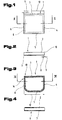
- Figs. 1 and 2 show a support plate 1 in a schematically simplified representation.
- Such support plates 1 may be used, for example, for ovens, e.g. Stoves or the like, be used as a protective device for floors when the support plate 1 between the oven and the floor is arranged. It is thus possible to use floors, e.g. Flooring made of plastic, wooden floors or the like, in front of the hearth of a furnace falling down To protect embers or sparks. Of course it is also possible to use this support plate 1 as footprint for other arbitrary body.
- the support plate 1 comprises a top 2, a bottom 3 and arranged therebetween Side surfaces 4 to 7, wherein depending on the outer shape of the support plate 1 only individual of these side surfaces 4 to 7 may be arranged. For example, show circular support plates 1 only one side surface 3.
- the support plate 1 any outer shape, so for example square, rectangular, oval, round or the like., Have.
- the support plate 1 can at least partially by an inorganic melt product, For example, be formed glass, especially safety glass.
- the support plate 1 may have a multilayer structure, wherein at least one Layer should be formed from the inorganic melt product.
- a material 8 in particular be fixed on the underside 3 of the support plate 1, a material 8, in particular be fixed. This material 8 is at a distance 9 arranged from the outer side edges 10 of the support plate 1.
- the material 8 is to be able to compensate for bumps, a modulus of elasticity which is less than the elastic modulus of the inorganic Melting product.
- the material 8 may, for example, in particular liquid and be formed dust-impermeable seal and the shape of a sealing cord, a sealing profile of any shape or the like.
- a material for the material 8 e.g. an elastically deformable polymer material, silicone, Rubber, sponge rubber or the like. Be used.
- the material 8 is within a width 11 on the underside 3 of the support plate 1 arranged.
- the width 11 is only a fraction of the total width 12 of Support plate 1.
- the arrangement of the material 8 can be achieved that uneven floors and thus compensated height differences between the bottom and the support plate 1 can be prevented, so that it can be prevented in the episode that dirt, dust, Moisture, water or the like.
- the optical quality that is, the appearance of the support plate 1 constantly deteriorates over the period of use, whereby the support plate 1 is unsightly over time.
- a cleaning the support plate 1, in particular in the region of the bottom 3, is due to the usual on the top 2 standing heavy body, such as the stoves, difficult or not possible, since in particular such stoves only below crazy and can be lowered from the top 2 or in this case is also the release of the connection to a flue-gas extraction device, For example, a chimney necessary and thus with an increased dust load, for example, by soot particles to be expected.
- a protective device for fire pits as described in the aforementioned DE 92 03 789 U1 is known, but can not meet these requirements, as this protection device consists of a rigid safety glass plate which is unable to naturally compensate for existing bumps.
- the material 8 in addition to the arrangement of the material 8 in the region of the bottom 3 and the side surfaces 4 to 7 but it is of course possible that, as in a later embodiment is shown, the material 8 additionally arranged on the top 2 is, especially in the areas near the side surfaces 4 to 7.
- FIG. 3 and 4 an embodiment of the support plate 1 in plan view and in Front view cut in accordance with the line IV - IV in Fig. 3 schematically simplified shown.
- the support plate 1 in this case has a shape which is rectilinear extending side surface 7 and a round side surface 5, which now the two other side surfaces 6 and 7, characterized. This should be the possibility the diversity of the support plate 1 are shown.
- This embodiment of the support plate 1 in turn has on the bottom 3 the Material 8 on.
- surface configurations 14 be arranged on the upper side 2, in the area 13, surface configurations 14 be arranged.
- the width of the region 13 can only a part of the total width 12 of the support plate 1 include.
- the width of the region 13 extends over the total width 12 and thus the surface configurations 14 are arranged over the entire surface of the upper side 2.
- the surface designs 14 attached to the side surfaces 4 to 7 and / or the bottom 3 are.
- the surface designs 14 may be, for example, by means of a printing process getting produced. It is also possible, of course, the surface designs 14 as a foil or film parts and perform this on the appropriate pages, in particular the top 2 and / or the bottom 3 and / or the side surfaces 4 bis 7 attach, for example, stick. But it can also be one in the inorganic Melt product einbrennbare film can be used, so that a good bond between the films or the film parts and the inorganic melt product can be.
- Another possibility is to use both the film and the printing process next to each other for the support plate 1 to use, so that both a printed image on at least one of the surfaces of the support plate 1 as well as one at least partially arranged film is present.
- the support plate 1 makes it possible on the one hand, the support plate 1 to give a visually appealing appearance and on the other hand is It thus possible to arrange the material 8 on the support plate 1, that it normally can not be seen through a view from above on the support plate 1 can.
- the material 8 can be, for example, along the dot-dash line in FIG Line be arranged within the area 13 at the bottom 3, so that it through the surface designs 14 at least partially, preferably completely, is covered.
- such materials can be used for the material 8 which do not have any special aesthetic shapes or colors or the like.
- the surface designs 14 may be of any shape. For example These can be used as points, stripes, flat entities of any size or Embodiment or the like. Be formed. It can be used as any design Patterns are designed.
- the surface features 14 may be any color and may be For example, mixed dyeings are used.
- FIG. 5 and 6 show a further embodiment of the support plate 1, which in this example is designed as a round disc.
- this support plate 1 or all conceivable embodiments of the support plate 1 no sharp-edged side edges 10, but rather rounded side edges 10 have.
- the visual appearance of the support plate 1 is additionally changed and thus can also prevent possible injury from sharp edges become.
- the bottom 3 and / or the top 2 and / or the side surfaces 4 to 7 - this particular embodiment naturally has only one side surface 4 - at least partially frosted, for example by sandblasting, Etching, e.g. with hydrofluoric acid or the like.
- the matting can be different levels and can be designed so that the support plate 1 at least partially is opaque or opaque. It is thus a running, for example increasing matting possible.
- FIGs. 7 to 8 another embodiment of the support plate 1 is schematically shown in simplified form. This is to express that the surface designs 14 may have any shape and thus the support plate. 1 For example, a marble-like design or the like. Can be awarded.
- the surface configurations 14 on the Bottom 3 and be arranged in the bottom 3 so that they are at least partially between the material 8 and the inorganic melt product, so that the material 8 in turn can be withdrawn from consideration.
- the support plate is formed multi-layered, it goes without saying possible that the surface configurations 14 between the material 8 instead of the inorganic Melt product and arranged above, suitable layer of Support plate 1 are available.
- the material 8 can be mixed with the inorganic melt product, So for example, with the glass or the interposed surface designs 14 connected, in particular glued. Will for the training the surface designs 14 uses a film, it is possible to self-adhesive so that the film easily adheres to the inorganic melted product or a corresponding other layer of the support plate 1 can be attached. But it is also possible to offer the individual components separately or as a package, so that the user of the support plate 1 this according to his wishes can shape. In particular, it is also possible with multi-layer support plates 1, to offer the individual layers separately.
- the film is self-adhesive on both sides, it can be achieved that Also, the material 8 is easy to attach, so that the support plate without special Expense can be put together by laymen.
- Fig. 9 shows a variant of the support plate 1 is shown, in which the Material not only along the outer circumference, but additionally in an interior area 15, e.g. in the area of a footprint of a body to be worn attached is.
- This additional material 8 can according to the contour of the footprint a body to be worn or it is possible, as this is shown by the dashed lines in Fig. 9, additional material 8 also to install within these contours.
- this additional material 8 can be achieved be that, in particular, when the support plate 1 for heavy objects, such as This example, stoves are, is used, the support plate 1 in the field of Contact surface of the body to be supported is supported and thus a deflection the support plate 1 can be largely prevented in this area.
- To the additional material 8 is preferably arranged on the underside 3 of the support plate 1.
- any x-any design design design the support plate 1 with imprints or films or the like. Possible.
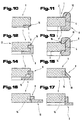
- FIGS. 10 to 17 show further possibilities in detail and schematically greatly simplified to attach the material 8 to or at least partially in the support plate 1, these possibilities by no means limit the invention but the invention also includes other conceivable embodiments.
- the material 8 may, for example, as shown in FIGS. 10, 12 to 17 in dash-dotted lines Representation shown, at least partially extend into a groove 16. This can be a secure bond, for example by gluing, between the material 8 and the overlying Layer of the support plate 1, for example, the inorganic melt product or the film or the imprint, and can be the material 8 are protected against lateral slippage.
- suitable Material choice for the material 8 is dispensed with an additional connection can be, for example, if the material of the polymer material with adhesive surface properties is formed.
- the arrangement of the groove 16 also allows that, especially if the support plate 1 is offered as a modular system, the support plate 1 easy and accurate fit can be put together by the buyer.
- the material 8 may be at least partially extend over all surfaces of the support plate 1, so both over a Part of the bottom 3, over the area of the side surfaces 4 to 7 and / or a Part of the top 2. Again, it is possible, as in Fig. 13 shows that at least one groove 16 in at least one layer of the support plate 1 is arranged.
- the material 8 Due to this design of the material 8 as a profile, which have any suitable shape can, on the one hand, on the other hand, it is possible, the material 8 of the exact fit or assign the layer (s) of the support plate 1 and can thus, in particular for the Case that the support plate 1 is made of a multi-layer, a secure cohesion of individual layers can be achieved. It is also possible, the side edges 10 to protect against accidental damage or may therefore the risk of injury be reduced by the side edges 10.
- the support plate can. 1 be formed multi-layered. At least one of the layers can be used as a glass plate, be designed as a plastic plate, as a ceramic plate or the like. Preferably is a top layer 17 made of a heat-resistant material, such as a Glass plate, formed.
- a film for example, a plastic film instead or in addition to arrange the surface configurations 14.
- this film or by area between the layers arranged film parts is an individual Design and adaptability of the support plate 1 to the body to be worn possible. For example, can slide parts of different colors between the layers to be ordered.
- the film is arranged only between two layers is or attached that between at least two layers imprints become.
- material 8 at least partially form so that it in a crooked Angle is inclined against the ground underneath or that a material underside 18 at least partially in the plane of the bottom 3 of the support plate. 1 is arranged.
- the inorganic melt product for example the glass plate
- the support plate 1 is made of a multi-layered is and between at least two layers a film is arranged, this film with Is provided recesses, so that a mixed color in different areas of the Support plate may arise, especially when using differently colored Layers.
- At least one of the layers or the entire support plate 1 has a increased thermal shock resistance, a corresponding bending strength or shock and impact resistance.
- the support plate 1 it is also possible that if a film is arranged between the layers, this is carried out so that in the event of damage or breakage of one of the layers of the support plate 1 the individual fragments, for example due to corresponding adhesive forces an adhesive layer, do not spread in the installation space of the support plate 1, but rather the support plate 1 held together substantially in shape becomes.
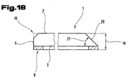
- Fig. 18 is a further embodiment of the support plate 1 according to the invention in shown schematically simplified representation. Based on this figure is the possibility are shown, at least one, preferably more of the side edges 10th be provided with a chamfer, for example, to grind (in Fig. 18 is the original Side edge 10 shown in dashed lines in the left part). Of course it is but also possible, this bevel already during the production of the single layer or layers, for example of the inorganic melt product, for the support plate 1, so that subsequent processing is no longer necessary is.
- the abrading or removal by means of suitable means of the side edge 10 offers the advantage that under certain circumstances a milky cloudy surface is created, so that thus arranged on the bottom 3 material 8 can be covered. It may therefore be an additional matting of this part of the support plate 1 under certain circumstances be waived or can be done supportive Matting.
- the chamfer may be over a total thickness 19 of the support plate 1 extend or, as shown in the left part of Fig. 18, only part of the total thickness 19 can be bevelled.
Landscapes
- Engineering & Computer Science (AREA)
- Chemical & Material Sciences (AREA)
- Combustion & Propulsion (AREA)
- Mechanical Engineering (AREA)
- General Engineering & Computer Science (AREA)
- Polishing Bodies And Polishing Tools (AREA)
- Photoreceptors In Electrophotography (AREA)
- Surface Treatment Of Glass (AREA)
- Laminated Bodies (AREA)
Claims (23)
- Plaque de support (1), notamment pour des fours, par exemple des fours à cheminée, avec un côté supérieur (2), un côté inférieur (3) et avec des surfaces latérales (4 à 7), disposées entre ceux-ci, avec une construction en au moins une couche, où au moins une couche est réalisée en un produit de fusion inorganique, par exemple en verre, notamment en verre de sécurité, caractérisée en ce qu'il est disposé dans la zone des surfaces latérales (4 à 7) et/ou du côté inférieur (3) au moins par zones un matériau (8) qui fait saillie au moins par zones à l'état non chargé sur le côté inférieur (3), et dont le module d'élasticité est plus bas que celui du produit de fusion inorganique.
- Plaque de support selon la revendication 1, caractérisée en ce que le matériau est disposé au moins par zones le long des arêtes latérales (10) et/ou à une distance de celles-ci.
- Plaque de support selon la revendication 2, caractérisée en ce que le matériau (8) est disposé dans la zone de tout le pourtour de la plaque de support (1).
- Plaque de support selon l'une des revendications précédentes, caractérisée en ce que le matériau (8) est disposé sur le côté inférieur (3) également dans une zone intérieure (15), par exemple dans la zone d'une face d'appui d'un corps à supporter, notamment d'un four, par exemple en correspondant à la face d'appui du contour et/ou à l'intérieur de ce pour tour.
- Plaque de support selon l'une des revendications précédentes, caractérisée en ce que le matériau (8) s'étend du côté inférieur (3) sur les surfaces latérales (4 à 7) jusque dans la zone du côté supérieur (2), notamment dans la zone (13) du côté supérieur (2) associée aux surfaces latérales (4 à 7).
- Plaque de support selon l'une des revendications précédentes, caractérisée en ce qu'au moins l'une des couches est une plaque de verre, une plaque en matériau synthétique, une plaque céramique.
- Plaque de support selon l'une des revendications précédentes, caractérisée en ce que le côté inférieur (3) et/ou les surfaces latérales (4 à 7) et/ou le côté supérieur (2) est pourvu au moins par zones de configurations de surface (14), par exemple est imprimé.
- Plaque de support selon l'une des revendications précédentes, caractérisée en ce qu'il est disposé au moins par zones sur le côté inférieur (3) et/ou les surfaces latérales (4 à 7) et/ou le côté supérieur (2) une feuille, notamment une feuille pouvant être cuite dans le produit de fusion inorganique.
- Plaque de support selon la revendication 7 ou 8, caractérisée en ce que l'impression, respectivement la feuille est disposée entre le matériau (8) et le produit de fusion inorganique.
- Plaque de support selon l'une des revendications précédentes, caractérisée en ce que le matériau (8) s'étend au moins partiellement dans un évidement, par exemple une rainure (16) dans au moins l'une des surfaces latérales (4 à 7) et/ou le côté inférieur (3) et/ou le côté supérieur (2).
- Plaque de support selon l'une des revendications précédentes, caractérisée en ce que la plaque de support (1) est constituée de plusieurs couches, notamment de trois de façon qu'au moins l'une des couches médianes présente une plus petite grandeur que les autres couches.
- Plaque de support selon la revendication 11, caractérisée en ce qu'il est disposé au moins entre deux couches au moins une feuille, par exemple une feuille en matériau synthétique.
- Plaque de support selon l'une des revendications 8 à 12, caractérisée en ce que la feuille est disposée respectivement l'impression est réalisée de façon à produire un motif pré-définissable, par exemple un motif de marbre ou des réalisations en forme de point.
- Plaque de support selon l'une des revendications précédentes, caractérisée en ce que le matériau (8) est une garniture d'étanchéité notamment imperméable au liquide et à la poussière.
- Plaque de support selon la revendication 14, caractérisée en ce que le matériau (8) est réalisé comme cordon d'étanchéité ou comme profilé d'étanchéité.
- Plaque de support selon l'une des revendications précédentes, caractérisée en ce que le matériau (8) est constitué d'un matériau polymère notamment déformable élastiquement, de silicium, de caoutchouc ou de caoutchouc mousse.
- Plaque de support selon l'une des revendications précédentes, caractérisée en ce que le côté supérieur (2) et/ou le côté inférieur (3) et/ou les surfaces latérales (4 à 7) sont réalisées au moins par zones avec une finition dépolie respectivement de manière non transparente ou opaque, par exemple par sablage ou par attaque, par exemple avec de l'acide fluorhydrique.
- Plaque de support selon la revendication 17, caractérisée en ce que le matériau (8) est disposé sur respectivement au voisinage (13) des surfaces dépolies, notamment sur le côté inférieur (3) de la plaque de support (1).
- Plaque de support selon l'une des revendications 7 à 18, caractérisée en ce que le matériau (8) est assemblé avec le produit de fusion inorganique respectivement l'impression disposée sur celui-ci ou la feuille cuite, notamment par collage.
- Plaque de support selon l'une des revendications précédentes, caractérisée en ce que le produit de fusion inorganique est une plaque de verre transparente au moins par zones, par exemple, claire, une plaque en verre opale; une plaque de verre fumée ou une plaque de verre d'une coloration différente.
- Plaque de support selon l'une des revendications précédentes, caractérisée en ce qu'au moins deux couches ont une couleur différente.
- Plaque de support selon l'une des revendications précédentes, caractérisée en ce que la plaque de support (1) présente des formes extérieures sélectives, par exemple carrées, ovales ou rondes.
- Plaque de support selon l'une des revendications précédentes, caractérisée en ce qu'au moins l'une des arêtes latérales (10) est au moins partiellement rompue, qu'elle est pourvue par exemple d'un chanfrein.
Priority Applications (1)
| Application Number | Priority Date | Filing Date | Title |
|---|---|---|---|
| AT99111499T ATE239890T1 (de) | 1998-06-15 | 1999-06-14 | Tragplatte |
Applications Claiming Priority (2)
| Application Number | Priority Date | Filing Date | Title |
|---|---|---|---|
| AT102598 | 1998-06-15 | ||
| AT0102598A AT410970B (de) | 1998-06-15 | 1998-06-15 | Tragplatte |
Publications (2)
| Publication Number | Publication Date |
|---|---|
| EP0965794A1 EP0965794A1 (fr) | 1999-12-22 |
| EP0965794B1 true EP0965794B1 (fr) | 2003-05-07 |
Family
ID=3505082
Family Applications (1)
| Application Number | Title | Priority Date | Filing Date |
|---|---|---|---|
| EP99111499A Expired - Lifetime EP0965794B1 (fr) | 1998-06-15 | 1999-06-14 | Plaque de support |
Country Status (3)
| Country | Link |
|---|---|
| EP (1) | EP0965794B1 (fr) |
| AT (2) | AT410970B (fr) |
| DE (1) | DE59905409D1 (fr) |
Families Citing this family (1)
| Publication number | Priority date | Publication date | Assignee | Title |
|---|---|---|---|---|
| DE10143215B4 (de) * | 2001-09-04 | 2007-05-16 | Bodenplatten Kontor Kiel Gmbh | Schmutzlippe für insbesondere eine Funkenschutzplatte |
Family Cites Families (3)
| Publication number | Priority date | Publication date | Assignee | Title |
|---|---|---|---|---|
| US2199916A (en) * | 1938-01-21 | 1940-05-07 | Jackes Evans Mfg Company | Stove board |
| US4416251A (en) * | 1981-10-30 | 1983-11-22 | Rachels-Horton Industries, Inc. | Thermoshield |
| DE9203789U1 (de) * | 1992-03-20 | 1992-06-25 | Maier-Glas GmbH, 7920 Heidenheim | Schutzvorrichtung für Feuerstellen |
-
1998
- 1998-06-15 AT AT0102598A patent/AT410970B/de not_active IP Right Cessation
-
1999
- 1999-06-14 EP EP99111499A patent/EP0965794B1/fr not_active Expired - Lifetime
- 1999-06-14 DE DE59905409T patent/DE59905409D1/de not_active Expired - Lifetime
- 1999-06-14 AT AT99111499T patent/ATE239890T1/de active
Also Published As
| Publication number | Publication date |
|---|---|
| AT410970B (de) | 2003-09-25 |
| DE59905409D1 (de) | 2003-06-12 |
| EP0965794A1 (fr) | 1999-12-22 |
| ATA102598A (de) | 2003-01-15 |
| ATE239890T1 (de) | 2003-05-15 |
Similar Documents
| Publication | Publication Date | Title |
|---|---|---|
| EP2586929B1 (fr) | Revêtement de sol | |
| DE20313661U1 (de) | Paneel mit geschützter V-Fuge | |
| DE20315676U1 (de) | Paneel, insbesondere Bodenpaneel | |
| DE3508438C2 (de) | Verfahren zur Herstellung einer Mehrschichtplatte mit verbessertem Abriebverhalten | |
| DE69504565T2 (de) | Leicht zerbrechbare Glasscheibe für Notausgänge oder dergleichen | |
| DE3937617A1 (de) | Ski | |
| EP3234280B1 (fr) | Panneau et ensemble de panneaux comportant une pluralité de ces panneaux | |
| EP0965794B1 (fr) | Plaque de support | |
| DE202011107236U1 (de) | Fußbodenbelag | |
| DE202010004016U1 (de) | Verbundplatte mit Arbeitsplatte und Trägerplatte sowie einer Sichtkantenverkleidung | |
| EP0951597A1 (fr) | Fa ade destinee notamment a des appareils electromenagers | |
| DE20021384U1 (de) | Dunstabzugshaube für Kochstellen mit einer oder mehreren wendbaren Dekorplatten | |
| DE3433547C2 (de) | Pflasterplatte | |
| DE69414269T2 (de) | Verfahren zur verbesserung einer arbeitsfläche und abdeckfläche hierfür | |
| DE19528719C1 (de) | Arbeitsplatte mit Deckschicht aus Metallblech | |
| DE20016842U1 (de) | Profilleiste, insbesondere Kantenleiste für die Möbelindustrie | |
| DE9206157U1 (de) | Labortischplatte mit Randwulst | |
| DE102008038009B4 (de) | Profilleiste und Möbelstück | |
| DE19917185A1 (de) | Boden- und/oder Wandbelag | |
| EP1299604A1 (fr) | Revetement de surface en liege et son procede de production | |
| DE102007023241B4 (de) | Laminatpaneel mit eingefärbtem Kern | |
| DE202022000573U1 (de) | Puzzle und Verbundkörper mit einem Puzzle | |
| DE9302731U1 (de) | Bodenplatte | |
| DE102017117648A1 (de) | Kunststoffpaneel | |
| DE202007007473U1 (de) | Laminatpaneel mit eingefärbtem Kern |
Legal Events
| Date | Code | Title | Description |
|---|---|---|---|
| PUAI | Public reference made under article 153(3) epc to a published international application that has entered the european phase |
Free format text: ORIGINAL CODE: 0009012 |
|
| AK | Designated contracting states |
Kind code of ref document: A1 Designated state(s): AT BE CH DE FR IT LI NL SE |
|
| AX | Request for extension of the european patent |
Free format text: AL;LT;LV;MK;RO;SI |
|
| 17P | Request for examination filed |
Effective date: 20000229 |
|
| AKX | Designation fees paid |
Free format text: AT BE CH DE FR IT LI NL SE |
|
| 17Q | First examination report despatched |
Effective date: 20020612 |
|
| GRAH | Despatch of communication of intention to grant a patent |
Free format text: ORIGINAL CODE: EPIDOS IGRA |
|
| GRAH | Despatch of communication of intention to grant a patent |
Free format text: ORIGINAL CODE: EPIDOS IGRA |
|
| GRAA | (expected) grant |
Free format text: ORIGINAL CODE: 0009210 |
|
| AK | Designated contracting states |
Designated state(s): AT BE CH DE FR IT LI NL SE |
|
| PG25 | Lapsed in a contracting state [announced via postgrant information from national office to epo] |
Ref country code: NL Free format text: LAPSE BECAUSE OF FAILURE TO SUBMIT A TRANSLATION OF THE DESCRIPTION OR TO PAY THE FEE WITHIN THE PRESCRIBED TIME-LIMIT Effective date: 20030507 Ref country code: IT Free format text: LAPSE BECAUSE OF FAILURE TO SUBMIT A TRANSLATION OF THE DESCRIPTION OR TO PAY THE FEE WITHIN THE PRESCRIBED TIME-LIMIT;WARNING: LAPSES OF ITALIAN PATENTS WITH EFFECTIVE DATE BEFORE 2007 MAY HAVE OCCURRED AT ANY TIME BEFORE 2007. THE CORRECT EFFECTIVE DATE MAY BE DIFFERENT FROM THE ONE RECORDED. Effective date: 20030507 Ref country code: FR Free format text: LAPSE BECAUSE OF FAILURE TO SUBMIT A TRANSLATION OF THE DESCRIPTION OR TO PAY THE FEE WITHIN THE PRESCRIBED TIME-LIMIT Effective date: 20030507 |
|
| REG | Reference to a national code |
Ref country code: CH Ref legal event code: EP |
|
| REF | Corresponds to: |
Ref document number: 59905409 Country of ref document: DE Date of ref document: 20030612 Kind code of ref document: P |
|
| PG25 | Lapsed in a contracting state [announced via postgrant information from national office to epo] |
Ref country code: BE Free format text: LAPSE BECAUSE OF NON-PAYMENT OF DUE FEES Effective date: 20030630 |
|
| PG25 | Lapsed in a contracting state [announced via postgrant information from national office to epo] |
Ref country code: SE Free format text: LAPSE BECAUSE OF FAILURE TO SUBMIT A TRANSLATION OF THE DESCRIPTION OR TO PAY THE FEE WITHIN THE PRESCRIBED TIME-LIMIT Effective date: 20030807 |
|
| REG | Reference to a national code |
Ref country code: CH Ref legal event code: NV Representative=s name: ABP PATENT NETWORK SWISS GMBH |
|
| NLV1 | Nl: lapsed or annulled due to failure to fulfill the requirements of art. 29p and 29m of the patents act | ||
| BERE | Be: lapsed |
Owner name: *RIENER KARL STEFAN Effective date: 20030630 |
|
| PLBE | No opposition filed within time limit |
Free format text: ORIGINAL CODE: 0009261 |
|
| STAA | Information on the status of an ep patent application or granted ep patent |
Free format text: STATUS: NO OPPOSITION FILED WITHIN TIME LIMIT |
|
| 26N | No opposition filed |
Effective date: 20040210 |
|
| EN | Fr: translation not filed | ||
| PGFP | Annual fee paid to national office [announced via postgrant information from national office to epo] |
Ref country code: CH Payment date: 20130624 Year of fee payment: 15 |
|
| REG | Reference to a national code |
Ref country code: CH Ref legal event code: PK Free format text: DER VETRETER LAUTETE AB DEM 5.3.2003 RICHTIG: ABP PATENT NETWORK SWISS GMBH Ref country code: CH Ref legal event code: NV Representative=s name: ABP PATENT NETWORK AG, CH Ref country code: CH Ref legal event code: NV Representative=s name: ABP PATENT NETWORK SWISS GMBH, CH |
|
| REG | Reference to a national code |
Ref country code: CH Ref legal event code: PL |
|
| PG25 | Lapsed in a contracting state [announced via postgrant information from national office to epo] |
Ref country code: LI Free format text: LAPSE BECAUSE OF NON-PAYMENT OF DUE FEES Effective date: 20140630 Ref country code: CH Free format text: LAPSE BECAUSE OF NON-PAYMENT OF DUE FEES Effective date: 20140630 |
|
| PGFP | Annual fee paid to national office [announced via postgrant information from national office to epo] |
Ref country code: DE Payment date: 20160608 Year of fee payment: 18 |
|
| PGFP | Annual fee paid to national office [announced via postgrant information from national office to epo] |
Ref country code: AT Payment date: 20160607 Year of fee payment: 18 |
|
| REG | Reference to a national code |
Ref country code: DE Ref legal event code: R119 Ref document number: 59905409 Country of ref document: DE |
|
| REG | Reference to a national code |
Ref country code: AT Ref legal event code: MM01 Ref document number: 239890 Country of ref document: AT Kind code of ref document: T Effective date: 20170614 |
|
| PG25 | Lapsed in a contracting state [announced via postgrant information from national office to epo] |
Ref country code: DE Free format text: LAPSE BECAUSE OF NON-PAYMENT OF DUE FEES Effective date: 20180103 |
|
| PG25 | Lapsed in a contracting state [announced via postgrant information from national office to epo] |
Ref country code: AT Free format text: LAPSE BECAUSE OF NON-PAYMENT OF DUE FEES Effective date: 20170614 |