EP0965794A1 - Plaque de support - Google Patents
Plaque de support Download PDFInfo
- Publication number
- EP0965794A1 EP0965794A1 EP99111499A EP99111499A EP0965794A1 EP 0965794 A1 EP0965794 A1 EP 0965794A1 EP 99111499 A EP99111499 A EP 99111499A EP 99111499 A EP99111499 A EP 99111499A EP 0965794 A1 EP0965794 A1 EP 0965794A1
- Authority
- EP
- European Patent Office
- Prior art keywords
- support plate
- plate according
- film
- layers
- underside
- Prior art date
- Legal status (The legal status is an assumption and is not a legal conclusion. Google has not performed a legal analysis and makes no representation as to the accuracy of the status listed.)
- Granted
Links
- 239000000463 material Substances 0.000 claims abstract description 73
- 239000011521 glass Substances 0.000 claims abstract description 21
- 239000010410 layer Substances 0.000 claims description 39
- 238000013461 design Methods 0.000 claims description 33
- 239000005336 safety glass Substances 0.000 claims description 6
- KRHYYFGTRYWZRS-UHFFFAOYSA-N Fluorane Chemical compound F KRHYYFGTRYWZRS-UHFFFAOYSA-N 0.000 claims description 4
- 239000003086 colorant Substances 0.000 claims description 4
- 239000000428 dust Substances 0.000 claims description 4
- 238000002844 melting Methods 0.000 claims description 4
- 230000008018 melting Effects 0.000 claims description 4
- 239000004033 plastic Substances 0.000 claims description 4
- 238000007789 sealing Methods 0.000 claims description 4
- 229920001971 elastomer Polymers 0.000 claims description 3
- 239000007788 liquid Substances 0.000 claims description 3
- 239000002861 polymer material Substances 0.000 claims description 3
- 238000012549 training Methods 0.000 claims description 3
- 239000000919 ceramic Substances 0.000 claims description 2
- 239000013078 crystal Substances 0.000 claims description 2
- 238000005530 etching Methods 0.000 claims description 2
- 239000002985 plastic film Substances 0.000 claims description 2
- 229920006255 plastic film Polymers 0.000 claims description 2
- 229920001296 polysiloxane Polymers 0.000 claims description 2
- 238000005488 sandblasting Methods 0.000 claims description 2
- 229920001821 foam rubber Polymers 0.000 claims 1
- 239000005338 frosted glass Substances 0.000 claims 1
- 239000004579 marble Substances 0.000 claims 1
- 239000002356 single layer Substances 0.000 claims 1
- 239000000853 adhesive Substances 0.000 description 7
- 230000006378 damage Effects 0.000 description 7
- 238000011161 development Methods 0.000 description 6
- 230000018109 developmental process Effects 0.000 description 6
- 230000001070 adhesive effect Effects 0.000 description 5
- 230000003287 optical effect Effects 0.000 description 5
- 230000001681 protective effect Effects 0.000 description 4
- 238000009434 installation Methods 0.000 description 3
- 238000000034 method Methods 0.000 description 3
- 208000027418 Wounds and injury Diseases 0.000 description 2
- 238000004026 adhesive bonding Methods 0.000 description 2
- 208000014674 injury Diseases 0.000 description 2
- 239000002245 particle Substances 0.000 description 2
- 238000012545 processing Methods 0.000 description 2
- 230000035939 shock Effects 0.000 description 2
- 239000002689 soil Substances 0.000 description 2
- 238000012546 transfer Methods 0.000 description 2
- XLYOFNOQVPJJNP-UHFFFAOYSA-N water Substances O XLYOFNOQVPJJNP-UHFFFAOYSA-N 0.000 description 2
- UGFAIRIUMAVXCW-UHFFFAOYSA-N Carbon monoxide Chemical compound [O+]#[C-] UGFAIRIUMAVXCW-UHFFFAOYSA-N 0.000 description 1
- -1 Moisture Substances 0.000 description 1
- 241000237536 Mytilus edulis Species 0.000 description 1
- 238000009825 accumulation Methods 0.000 description 1
- 239000012790 adhesive layer Substances 0.000 description 1
- 238000004140 cleaning Methods 0.000 description 1
- 238000010276 construction Methods 0.000 description 1
- 230000007613 environmental effect Effects 0.000 description 1
- 238000000605 extraction Methods 0.000 description 1
- 238000009408 flooring Methods 0.000 description 1
- 239000003546 flue gas Substances 0.000 description 1
- 239000011888 foil Substances 0.000 description 1
- 239000012634 fragment Substances 0.000 description 1
- 238000000227 grinding Methods 0.000 description 1
- 239000003779 heat-resistant material Substances 0.000 description 1
- 238000004519 manufacturing process Methods 0.000 description 1
- 239000008267 milk Substances 0.000 description 1
- 210000004080 milk Anatomy 0.000 description 1
- 235000013336 milk Nutrition 0.000 description 1
- 235000020638 mussel Nutrition 0.000 description 1
- 239000011505 plaster Substances 0.000 description 1
- 239000007787 solid Substances 0.000 description 1
- 239000004071 soot Substances 0.000 description 1
- 239000004575 stone Substances 0.000 description 1
- 239000000126 substance Substances 0.000 description 1
- 230000003319 supportive effect Effects 0.000 description 1
- 230000007704 transition Effects 0.000 description 1
- 230000000007 visual effect Effects 0.000 description 1
Images

Classifications
-
- F—MECHANICAL ENGINEERING; LIGHTING; HEATING; WEAPONS; BLASTING
- F24—HEATING; RANGES; VENTILATING
- F24B—DOMESTIC STOVES OR RANGES FOR SOLID FUELS; IMPLEMENTS FOR USE IN CONNECTION WITH STOVES OR RANGES
- F24B13/00—Details solely applicable to stoves or ranges burning solid fuels
- F24B13/002—Surrounds
Definitions
- the invention relates to a support plate, in particular for ovens, e.g. Stoves, according to the preamble of claim 1.
- a support plate of the generic type is e.g. known from DE 92 03 789 U1.
- the protective device for fireplaces in buildings described therein is from one Safety glass plate with increased resistance to temperature changes, flexural strength, Impact and shock resistance trained and can be in front of or under the fireplace be arranged.
- This safety glass plate is supposed to be compared to stone plates be visually more appealing and the respective floor or floor covering of the installation site Protect the safety glass plate from sparks from the fireplace. Disadvantageous with this glass plate is that with it unevenness of the arranged below Floor or floor covering can not be compensated and thus the bottom the glass plate over the period of use of the oven on it more dirty.
- the object of the invention is to further develop a support plate, in particular for ovens, that the support plate has its optical properties during the time of its use maintains even if it is only cleaned in the easily accessible places becomes.
- a further development according to claim 2 is also advantageous since it protects the Soil can be improved.
- an embodiment according to claim 4 is also advantageous, according to which the material in Area of a footprint of a body to be worn is arranged. So that's it on the one hand possible this additionally arranged material through the arranged above Body and can cause a deflection of the support plate due to the weight of the body to be carried on it can be largely prevented.
- a further development according to claim 5 is also advantageous, since it is possible the edges as well as the side surfaces of the support plate from unintended destruction or to protect damage.
- An advantage of the design according to claim 12 is that the multilayer Building a recess for the material to be recorded with simple means can be.
- An advantage of an embodiment according to claim 14 is that through the film or Imprint of the support plate can be given any design and this in particular can be tailored to the body to be worn.
- an embodiment variant according to claim 25 is also advantageous because so that a simple covering of the material can be achieved and also sharp Edges of the support plate can be avoided.
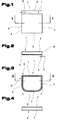
- Such support plates 1 can be used, for example, for ovens, e.g. Stoves or the like, be used as a protective device for floors when the support plate 1 between the oven and the floor. It is thus possible to use floors, e.g. Flooring made of plastic, wooden floors or the like, before falling from the fireplace of a stove To protect embers or sparks. Of course, it is also possible to use this support plate 1 as a footprint for any other body.
- the support plate 1 comprises a top 2, a bottom 3 and arranged in between Side surfaces 4 to 7, depending on the outer shape of the support plate 1 only some of these side surfaces 4 to 7 can be arranged.
- point circular support plates 1 only one side surface 3.
- the support plate 1 can have any external shape, for example square, rectangular, oval, round or the like.
- the support plate 1 can be at least partially replaced by an inorganic melt product, for example glass, in particular safety glass.
- an inorganic melt product for example glass, in particular safety glass.
- the support plate 1 can have a multilayer structure, at least one Layer should be formed from the inorganic melt product.
- a material can be on the underside 3 of the support plate 1 8 arranged, in particular be attached. This material 8 is at a distance 9 arranged from the outer side edges 10 of the support plate 1.
- the material 8 extends over the entire Extends the circumference of the support plate 1, it is possible that the material 8 only in some areas is arranged along the circumference of the support plate 1.
- the material 8 should have a modulus of elasticity have less than the elastic modulus of the inorganic Melt product.
- the material 8 can, for example, be in particular liquid and dustproof seal can be formed and can take the form of a sealing cord, have a sealing profile of any shape or the like.
- a material for material 8 e.g. an elastically deformable polymer material, silicone, Rubber, sponge rubber or the like can be used.
- the material 8 is preferably within a width 11 on the underside 3 of the support plate 1 arranged.
- the width 11 is only a fraction of the total width 12 of the Support plate 1.
- the material 8 By arranging the material 8 can be achieved that uneven floors and thus compensated for differences in height between the floor and the support plate 1 can be prevented, so that dirt, dust, Moisture, water or the like in the space between the support plate 1 and its footprint penetrate the floor of the installation site below.
- Such an accumulation of dirt, particles and moisture between the floor or a floor covering and the support plate 1 is the optical quality, i.e., the appearance of the support plate 1 deteriorates continuously over the period of its use, whereby the support plate 1 becomes unsightly over time.
- a cleaning the support plate 1, especially in the area of the bottom 3, is due to the usual heavy bodies standing on the top 2, for example the stoves, difficult or not possible, since such stoves in particular only under great effort can be crazy or down from the top 2 or in this case is also the loosening of the connection to a flue gas extraction device, for example a chimney is necessary and therefore with an increased dust load, for example due to soot particles.
- a protective device for fireplaces as described in DE 92 03 mentioned at the beginning 789 U1 is known, but cannot meet these requirements because of this protective device consists of a rigid safety glass plate, which is not able naturally compensate for uneven floors.
- the material 8 is additionally arranged on the top 2 , especially in the areas near the side surfaces 4 to 7.
- FIG. 3 and 4 is a variant of the support plate 1 in plan view and in Front view cut along the line IV - IV in Fig. 3 schematically simplified shown.
- the support plate 1 has a shape that by a straight line extending side surface 7 and a round side surface 5, which are now the two includes other side surfaces 6 and 7, characterized. This is supposed to be the opportunity the diversity of the support plate 1 are shown.
- This variant of the support plate 1 in turn has the bottom 3 Material 8 on.
- Surface designs 14 can be provided on top 2 in area 13 be arranged.
- the width of the area 13 can only be part of the total width 12 of the support plate 1 include.
- the width of the area 13 extends over the total width 12 and thus the surface designs 14 are arranged over the entire surface of the top 2.
- the surface designs in addition to or instead of the top 2 14 attached to the side surfaces 4 to 7 and / or the bottom 3 are.
- the surface designs 14 can, for example, with the aid of a printing process getting produced. It is of course also possible to design the surfaces 14 to execute as a film or film parts and this on the corresponding sides, in particular the top 2 and / or the bottom 3 and / or the side surfaces 4 to 7 to attach, for example gluing. But it can also be one in the inorganic Melting product burnable film can be used, so that a good bond between the films or the film parts and the inorganic melt product can be.
- Another option is to use both the film and the printing process to use next to each other for the support plate 1, so that both a print image on at least one of the surfaces of the support plate 1 and one at least partially thereon arranged film is present.
- the application of the film or the printing of patterns on the one hand enables to give the support plate 1 a visually appealing exterior and on the other hand it is thereby possible to arrange the material 8 on the support plate 1 so that it normally cannot be seen by looking at the support plate 1 from above can.
- the material 8 can for example be along the dot-dash line in FIG. 3 Line within the area 13 to be arranged on the bottom 3, so that it through the surface designs 14 at least partially, preferably completely, is covered.
- such materials can also be used for the material 8 which have no special aesthetic shapes or colors or the like.
- the surface designs 14 can have any shape. For example these can be dots, stripes, flat structures of any size or Design or the like. Be formed. It can be used for any design Pattern can be designed.
- the surface designs 14 can have any color and can for example, mixed colors can also be used.
- FIG. 5 and 6 show a further embodiment of the support plate 1, which in this example is designed as a round disc.
- this support plate 1 or all conceivable variants of the support plate 1 no sharp-edged side edges 10, but rather rounded side edges 10 have.
- the optical appearance of the support plate 1 can also be changed and can also prevent possible injuries from sharp edges become.
- the dotted area in area 13 is intended to indicate that it is possible, the bottom 3 and / or the top 2 and / or the side surfaces 4 to 7 - this special embodiment naturally has only one side surface 4 - can be matted at least in some areas, for example by sandblasting, Etching, e.g. with hydrofluoric acid or the like.
- the matting can have different stages have and can be designed so that the support plate 1 at least in some areas is opaque or opaque. It is also a trending, for example increasing matting possible.
- FIG. 7 to 8 another embodiment of the support plate 1 is schematic shown in simplified form. This is intended to express that the surface designs 14 can have any shape and thus the support plate 1 for example, a marble-like design or the like can be awarded.
- the surface designs 14 on the Bottom 3 or in the bottom 3 so that they are at least partially between the material 8 and the inorganic melt product, so that the material 8 can in turn be removed from consideration.
- the support plate is multi-layered, it goes without saying possible that the surface designs 14 between the material 8 instead of the inorganic Melting product and the appropriate layer of Support plate 1 are available.
- the material 8 can be mixed with the inorganic melt product, for example with the glass or the surface designs arranged between them 14 connected, in particular glued.
- Used for training of the surface designs 14 uses a film, it is possible to make it self-adhesive so that the film simply adheres to the inorganic melt product or a corresponding other layer of the support plate 1 can be attached.
- multi-layer support plates 1 to offer the individual layers separately.
- the film is self-adhesive on both sides, it can be achieved that the material 8 is easy to attach, so that the support plate without any special Effort can also be put together by laypeople.
- FIG. 9 an embodiment of the support plate 1 is shown, in which the Material not only along the outer circumference, but also inside 15, e.g. attached in the area of a footprint of a body to be worn is.
- This additional material 8 can correspond to the contour of the footprint a body to be worn or it is possible, like this is shown in Fig. 9 by the dashed lines, additional material 8 also to be placed within these contours.
- This additional material 8 can be achieved be that especially when the support plate 1 for heavy objects, such as These are, for example, stoves, the support plate 1 is used in the area Footprint of the body to be supported is supported and thus a deflection the support plate 1 can be largely prevented in this area.
- To the additional material 8 is preferably arranged on the underside 3 of the support plate 1.
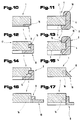
- the material 8 can, for example, as in FIGS. 10, 12 to 17 in dashed lines Shown illustration, extend at least partially into a groove 16. With that a secure bond, for example by gluing, between the material 8 and the one above it Layer of the support plate 1, for example the inorganic melt product or the film or the print, can be produced and the material 8 be protected against slipping sideways.
- the arrangement of the groove 16 also allows that, especially when the support plate 1 is offered as a modular system, the support plate 1 simple and precise can be put together by the buyer.
- the material 8 can at least partially Extend over all surfaces of the support plate 1, that is, both over one Part of the bottom 3, over the area of the side surfaces 4 to 7 and / or one Part of the upper side 2.
- Fig. 13 shows that at least one groove 16 in at least one layer of the support plate 1 is arranged.
- the material 8 By designing the material 8 as a profile, which have any suitable shape can, on the one hand, it is in turn possible for the material 8 to fit the or assign the layer (s) of the support plate 1 and can thus, in particular for the Case that the support plate 1 is multi-layered, a secure cohesion of individual layers can be achieved. But it is also possible, the side edges 10 to protect against unintentional damage or can reduce the risk of injury be reduced by the side edges 10. It also offers one Arrangement of the material 8 an additional design element for the overall appearance the support plate 1 and can be achieved that if, for example Ash falls out of the hearth of a furnace onto the support plate 1, that this Ash is collected on the top 2 and can be easily removed or this is not distributed over the entire space in which the support plate 1 is used.
- the support plate 1 be formed in multiple layers. At least one of the layers can be used as a glass plate, be designed as a plastic plate, a ceramic plate or the like. Preferably is an uppermost layer 17 made of a heat-resistant material, for example one Glass plate, formed.
- the multilayer structure makes it possible to at least one of the layers in their size to be smaller than the other layers, so that the groove 16 without additional Steps can be made and the material in turn in this Groove 16 can at least partially engage.
- the multilayer structure also makes it possible to move between the individual Layers of a film, for example a plastic film instead of or in addition to arrange the surface designs 14.
- a film for example a plastic film instead of or in addition to arrange the surface designs 14.
- this film or by area film parts arranged between the layers is an individual one Design and adaptability of the support plate 1 to the body to be carried possible.
- film parts of different colors can be between the layers to be ordered.
- the film it is of course possible for the film to be arranged only between two layers is or that between at least two layers of imprints become.
- Such a design of the film or the imprints can achieve that these are protected from environmental influences and, for example, wear-resistant in the support plate 1 are arranged. It can also be used to clean the top 2 can be facilitated, since this can now be carried out completely smooth, as is the case with the variant of the application of the film or the imprints on the underside 3 is the case.
- material 8 at least partially so that it lopsided in one Angle is inclined towards the floor below or that a material underside 18 at least in regions in the plane of the underside 3 of the support plate 1 is arranged.
- the inorganic melt product for example the glass plate
- the support plate 1 is made of multiple layers and a film is arranged between at least two layers, this film with Recesses is provided so that a mixed color in different areas of the Carrier plate can arise, especially when using differently colored Layers.
- At least one of the layers or the entire support plate 1 preferably has one increased resistance to temperature changes, a corresponding flexural strength or impact and shock resistance.
- the support plate 1 it is also possible that if a film is arranged between the layers, this is carried out in such a way that in the event of any damage or if one of the layers of the support plate breaks 1 the individual fragments, for example due to corresponding adhesive forces an adhesive layer, is not distributed in the installation space of the support plate 1, rather, the support plate 1 is essentially held together in its shape becomes.
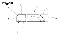
- FIG. 18 shows a further embodiment variant of the support plate 1 according to the invention shown schematically simplified representation. Based on this figure, the possibility should are represented, at least one, preferably several, of the side edges 10 to be chamfered, for example to grind (in Fig. 18 is the original Side edge 10 shown in dashed lines in the left part). Of course it is but this chamfer is also possible during the production of the individual layer or layers, for example of the inorganic melt product, for the support plate 1 to be considered, so that subsequent processing is no longer necessary is.
- grinding or removal by means of suitable means of the side edge 10 offers the advantage that a milky, cloudy surface is created, so that the material 8 arranged on the underside 3 can be covered. Under certain circumstances, this can result in additional matting of this part of the support plate 1 can be dispensed with or the matting can take place in a supportive manner.
- the chamfer can extend over an overall thickness 19 of the support plate 1 or, as shown in the left part of FIG. 18, only a part of the total thickness 19 can be chamfered.
- rounded inclined surfaces 20 are also possible, for example a rounded transition between the inclined surface 20 and the top 2 or the bottom 3 or the side surfaces 4 to 7 can be reached.
- FIGS. 1, 2; 3, 4; 5, 6; 7, 8; 9; 10; 11; 12; 13; 14; 15; 16; 17; 18 shown designs the subject of independent, inventive Form solutions.
- the relevant tasks according to the invention and solutions can be found in the detailed descriptions of these figures.
Landscapes
- Engineering & Computer Science (AREA)
- Chemical & Material Sciences (AREA)
- Combustion & Propulsion (AREA)
- Mechanical Engineering (AREA)
- General Engineering & Computer Science (AREA)
- Polishing Bodies And Polishing Tools (AREA)
- Photoreceptors In Electrophotography (AREA)
- Surface Treatment Of Glass (AREA)
- Laminated Bodies (AREA)
Priority Applications (1)
| Application Number | Priority Date | Filing Date | Title |
|---|---|---|---|
| AT99111499T ATE239890T1 (de) | 1998-06-15 | 1999-06-14 | Tragplatte |
Applications Claiming Priority (2)
| Application Number | Priority Date | Filing Date | Title |
|---|---|---|---|
| AT102598 | 1998-06-15 | ||
| AT0102598A AT410970B (de) | 1998-06-15 | 1998-06-15 | Tragplatte |
Publications (2)
| Publication Number | Publication Date |
|---|---|
| EP0965794A1 true EP0965794A1 (fr) | 1999-12-22 |
| EP0965794B1 EP0965794B1 (fr) | 2003-05-07 |
Family
ID=3505082
Family Applications (1)
| Application Number | Title | Priority Date | Filing Date |
|---|---|---|---|
| EP99111499A Expired - Lifetime EP0965794B1 (fr) | 1998-06-15 | 1999-06-14 | Plaque de support |
Country Status (3)
| Country | Link |
|---|---|
| EP (1) | EP0965794B1 (fr) |
| AT (2) | AT410970B (fr) |
| DE (1) | DE59905409D1 (fr) |
Cited By (1)
| Publication number | Priority date | Publication date | Assignee | Title |
|---|---|---|---|---|
| DE10143215B4 (de) * | 2001-09-04 | 2007-05-16 | Bodenplatten Kontor Kiel Gmbh | Schmutzlippe für insbesondere eine Funkenschutzplatte |
Citations (3)
| Publication number | Priority date | Publication date | Assignee | Title |
|---|---|---|---|---|
| US2199916A (en) * | 1938-01-21 | 1940-05-07 | Jackes Evans Mfg Company | Stove board |
| US4416251A (en) * | 1981-10-30 | 1983-11-22 | Rachels-Horton Industries, Inc. | Thermoshield |
| DE9203789U1 (de) | 1992-03-20 | 1992-06-25 | Maier-Glas GmbH, 7920 Heidenheim | Schutzvorrichtung für Feuerstellen |
-
1998
- 1998-06-15 AT AT0102598A patent/AT410970B/de not_active IP Right Cessation
-
1999
- 1999-06-14 EP EP99111499A patent/EP0965794B1/fr not_active Expired - Lifetime
- 1999-06-14 DE DE59905409T patent/DE59905409D1/de not_active Expired - Lifetime
- 1999-06-14 AT AT99111499T patent/ATE239890T1/de active
Patent Citations (3)
| Publication number | Priority date | Publication date | Assignee | Title |
|---|---|---|---|---|
| US2199916A (en) * | 1938-01-21 | 1940-05-07 | Jackes Evans Mfg Company | Stove board |
| US4416251A (en) * | 1981-10-30 | 1983-11-22 | Rachels-Horton Industries, Inc. | Thermoshield |
| DE9203789U1 (de) | 1992-03-20 | 1992-06-25 | Maier-Glas GmbH, 7920 Heidenheim | Schutzvorrichtung für Feuerstellen |
Cited By (1)
| Publication number | Priority date | Publication date | Assignee | Title |
|---|---|---|---|---|
| DE10143215B4 (de) * | 2001-09-04 | 2007-05-16 | Bodenplatten Kontor Kiel Gmbh | Schmutzlippe für insbesondere eine Funkenschutzplatte |
Also Published As
| Publication number | Publication date |
|---|---|
| AT410970B (de) | 2003-09-25 |
| EP0965794B1 (fr) | 2003-05-07 |
| DE59905409D1 (de) | 2003-06-12 |
| ATA102598A (de) | 2003-01-15 |
| ATE239890T1 (de) | 2003-05-15 |
Similar Documents
| Publication | Publication Date | Title |
|---|---|---|
| DE60115275T2 (de) | Verbundbodenfliese | |
| DE01984017T1 (de) | Bodenbedeckung | |
| DE202011109214U1 (de) | Küchenarbeitsplatte | |
| DE2758041C2 (de) | Verwendung eines aus mindestens zwei übereinander angeordneten Folien, insbesondere Kunststoffolien, bestehenden Bauelements | |
| DE10253553A1 (de) | Schwimmend verlegbares Fußbodenelement | |
| DE3937617A1 (de) | Ski | |
| EP1475490A2 (fr) | Revêtement de sol en un matériau élastomère avec une surface structurée | |
| EP0513707B2 (fr) | Plaque de verre et procédé pour sa production | |
| AT410970B (de) | Tragplatte | |
| DE2659316C2 (de) | Einlagekörper für Scheinfugen, insbesondere in Betonfahrbahnplatten | |
| AT401791B (de) | Verbundplatte mit wenigstens einer deckschicht aus holz | |
| DE3916331A1 (de) | Kunststoffplatten fuer bauzwecke | |
| DE102005021662A1 (de) | Fußbodenpaneele | |
| DE20021384U1 (de) | Dunstabzugshaube für Kochstellen mit einer oder mehreren wendbaren Dekorplatten | |
| DE4011302C2 (de) | Wintermatte | |
| DE3433547C2 (de) | Pflasterplatte | |
| EP0951597A1 (fr) | Fa ade destinee notamment a des appareils electromenagers | |
| EP3306008A1 (fr) | Panneau composite de plancher en céramique | |
| DE10033495C2 (de) | Kork-Flächenverkleidung, insbesondere Kork-Bodenbelag, und Verfahren zu deren Herstellung | |
| DE102009009431A1 (de) | Platte, deren Verwendung sowie Herstellungsverfahren dafür | |
| DE8702601U1 (de) | Vorrichtung zur Verschleißminderung | |
| DE9401553U1 (de) | Elastischer und gemusterter Fußbodenbelag aus Rcycling-, Gummi- oder elastischen Kunststoffgranulaten | |
| DE3235252A1 (de) | Waermedaemmplatte | |
| DE29800244U1 (de) | Anordnung zur Lagefixierung von zu einem Bodenbelag fügbaren Paneelen | |
| DE19917185A1 (de) | Boden- und/oder Wandbelag |
Legal Events
| Date | Code | Title | Description |
|---|---|---|---|
| PUAI | Public reference made under article 153(3) epc to a published international application that has entered the european phase |
Free format text: ORIGINAL CODE: 0009012 |
|
| AK | Designated contracting states |
Kind code of ref document: A1 Designated state(s): AT BE CH DE FR IT LI NL SE |
|
| AX | Request for extension of the european patent |
Free format text: AL;LT;LV;MK;RO;SI |
|
| 17P | Request for examination filed |
Effective date: 20000229 |
|
| AKX | Designation fees paid |
Free format text: AT BE CH DE FR IT LI NL SE |
|
| 17Q | First examination report despatched |
Effective date: 20020612 |
|
| GRAH | Despatch of communication of intention to grant a patent |
Free format text: ORIGINAL CODE: EPIDOS IGRA |
|
| GRAH | Despatch of communication of intention to grant a patent |
Free format text: ORIGINAL CODE: EPIDOS IGRA |
|
| GRAA | (expected) grant |
Free format text: ORIGINAL CODE: 0009210 |
|
| AK | Designated contracting states |
Designated state(s): AT BE CH DE FR IT LI NL SE |
|
| PG25 | Lapsed in a contracting state [announced via postgrant information from national office to epo] |
Ref country code: NL Free format text: LAPSE BECAUSE OF FAILURE TO SUBMIT A TRANSLATION OF THE DESCRIPTION OR TO PAY THE FEE WITHIN THE PRESCRIBED TIME-LIMIT Effective date: 20030507 Ref country code: IT Free format text: LAPSE BECAUSE OF FAILURE TO SUBMIT A TRANSLATION OF THE DESCRIPTION OR TO PAY THE FEE WITHIN THE PRESCRIBED TIME-LIMIT;WARNING: LAPSES OF ITALIAN PATENTS WITH EFFECTIVE DATE BEFORE 2007 MAY HAVE OCCURRED AT ANY TIME BEFORE 2007. THE CORRECT EFFECTIVE DATE MAY BE DIFFERENT FROM THE ONE RECORDED. Effective date: 20030507 Ref country code: FR Free format text: LAPSE BECAUSE OF FAILURE TO SUBMIT A TRANSLATION OF THE DESCRIPTION OR TO PAY THE FEE WITHIN THE PRESCRIBED TIME-LIMIT Effective date: 20030507 |
|
| REG | Reference to a national code |
Ref country code: CH Ref legal event code: EP |
|
| REF | Corresponds to: |
Ref document number: 59905409 Country of ref document: DE Date of ref document: 20030612 Kind code of ref document: P |
|
| PG25 | Lapsed in a contracting state [announced via postgrant information from national office to epo] |
Ref country code: BE Free format text: LAPSE BECAUSE OF NON-PAYMENT OF DUE FEES Effective date: 20030630 |
|
| PG25 | Lapsed in a contracting state [announced via postgrant information from national office to epo] |
Ref country code: SE Free format text: LAPSE BECAUSE OF FAILURE TO SUBMIT A TRANSLATION OF THE DESCRIPTION OR TO PAY THE FEE WITHIN THE PRESCRIBED TIME-LIMIT Effective date: 20030807 |
|
| REG | Reference to a national code |
Ref country code: CH Ref legal event code: NV Representative=s name: ABP PATENT NETWORK SWISS GMBH |
|
| NLV1 | Nl: lapsed or annulled due to failure to fulfill the requirements of art. 29p and 29m of the patents act | ||
| BERE | Be: lapsed |
Owner name: *RIENER KARL STEFAN Effective date: 20030630 |
|
| PLBE | No opposition filed within time limit |
Free format text: ORIGINAL CODE: 0009261 |
|
| STAA | Information on the status of an ep patent application or granted ep patent |
Free format text: STATUS: NO OPPOSITION FILED WITHIN TIME LIMIT |
|
| 26N | No opposition filed |
Effective date: 20040210 |
|
| EN | Fr: translation not filed | ||
| PGFP | Annual fee paid to national office [announced via postgrant information from national office to epo] |
Ref country code: CH Payment date: 20130624 Year of fee payment: 15 |
|
| REG | Reference to a national code |
Ref country code: CH Ref legal event code: PK Free format text: DER VETRETER LAUTETE AB DEM 5.3.2003 RICHTIG: ABP PATENT NETWORK SWISS GMBH Ref country code: CH Ref legal event code: NV Representative=s name: ABP PATENT NETWORK AG, CH Ref country code: CH Ref legal event code: NV Representative=s name: ABP PATENT NETWORK SWISS GMBH, CH |
|
| REG | Reference to a national code |
Ref country code: CH Ref legal event code: PL |
|
| PG25 | Lapsed in a contracting state [announced via postgrant information from national office to epo] |
Ref country code: LI Free format text: LAPSE BECAUSE OF NON-PAYMENT OF DUE FEES Effective date: 20140630 Ref country code: CH Free format text: LAPSE BECAUSE OF NON-PAYMENT OF DUE FEES Effective date: 20140630 |
|
| PGFP | Annual fee paid to national office [announced via postgrant information from national office to epo] |
Ref country code: DE Payment date: 20160608 Year of fee payment: 18 |
|
| PGFP | Annual fee paid to national office [announced via postgrant information from national office to epo] |
Ref country code: AT Payment date: 20160607 Year of fee payment: 18 |
|
| REG | Reference to a national code |
Ref country code: DE Ref legal event code: R119 Ref document number: 59905409 Country of ref document: DE |
|
| REG | Reference to a national code |
Ref country code: AT Ref legal event code: MM01 Ref document number: 239890 Country of ref document: AT Kind code of ref document: T Effective date: 20170614 |
|
| PG25 | Lapsed in a contracting state [announced via postgrant information from national office to epo] |
Ref country code: DE Free format text: LAPSE BECAUSE OF NON-PAYMENT OF DUE FEES Effective date: 20180103 |
|
| PG25 | Lapsed in a contracting state [announced via postgrant information from national office to epo] |
Ref country code: AT Free format text: LAPSE BECAUSE OF NON-PAYMENT OF DUE FEES Effective date: 20170614 |