EP0965809B1 - Stützvorrichtung für Produkte in einem Brennofen - Google Patents
Stützvorrichtung für Produkte in einem Brennofen Download PDFInfo
- Publication number
- EP0965809B1 EP0965809B1 EP19990401506 EP99401506A EP0965809B1 EP 0965809 B1 EP0965809 B1 EP 0965809B1 EP 19990401506 EP19990401506 EP 19990401506 EP 99401506 A EP99401506 A EP 99401506A EP 0965809 B1 EP0965809 B1 EP 0965809B1
- Authority
- EP
- European Patent Office
- Prior art keywords
- feet
- bars
- fact
- support according
- products
- Prior art date
- Legal status (The legal status is an assumption and is not a legal conclusion. Google has not performed a legal analysis and makes no representation as to the accuracy of the status listed.)
- Expired - Lifetime
Links
- 230000006978 adaptation Effects 0.000 claims description 5
- 230000000712 assembly Effects 0.000 description 4
- 238000000429 assembly Methods 0.000 description 4
- 230000000903 blocking effect Effects 0.000 description 3
- 230000000694 effects Effects 0.000 description 3
- 239000011819 refractory material Substances 0.000 description 3
- 238000010411 cooking Methods 0.000 description 2
- HBMJWWWQQXIZIP-UHFFFAOYSA-N silicon carbide Chemical compound [Si+]#[C-] HBMJWWWQQXIZIP-UHFFFAOYSA-N 0.000 description 2
- 229910010271 silicon carbide Inorganic materials 0.000 description 2
- 229910000831 Steel Inorganic materials 0.000 description 1
- 241001080024 Telles Species 0.000 description 1
- 240000008042 Zea mays Species 0.000 description 1
- 239000000470 constituent Substances 0.000 description 1
- 238000001816 cooling Methods 0.000 description 1
- 229910052878 cordierite Inorganic materials 0.000 description 1
- JSKIRARMQDRGJZ-UHFFFAOYSA-N dimagnesium dioxido-bis[(1-oxido-3-oxo-2,4,6,8,9-pentaoxa-1,3-disila-5,7-dialuminabicyclo[3.3.1]nonan-7-yl)oxy]silane Chemical compound [Mg++].[Mg++].[O-][Si]([O-])(O[Al]1O[Al]2O[Si](=O)O[Si]([O-])(O1)O2)O[Al]1O[Al]2O[Si](=O)O[Si]([O-])(O1)O2 JSKIRARMQDRGJZ-UHFFFAOYSA-N 0.000 description 1
- 238000001035 drying Methods 0.000 description 1
- 238000004534 enameling Methods 0.000 description 1
- 238000005265 energy consumption Methods 0.000 description 1
- 230000009970 fire resistant effect Effects 0.000 description 1
- 238000010438 heat treatment Methods 0.000 description 1
- 238000009434 installation Methods 0.000 description 1
- 239000000463 material Substances 0.000 description 1
- 238000000034 method Methods 0.000 description 1
- 230000000149 penetrating effect Effects 0.000 description 1
- 239000011214 refractory ceramic Substances 0.000 description 1
- 230000000284 resting effect Effects 0.000 description 1
- 238000005096 rolling process Methods 0.000 description 1
- 239000002356 single layer Substances 0.000 description 1
- 239000010959 steel Substances 0.000 description 1
Images



Classifications
-
- F—MECHANICAL ENGINEERING; LIGHTING; HEATING; WEAPONS; BLASTING
- F27—FURNACES; KILNS; OVENS; RETORTS
- F27D—DETAILS OR ACCESSORIES OF FURNACES, KILNS, OVENS OR RETORTS, IN SO FAR AS THEY ARE OF KINDS OCCURRING IN MORE THAN ONE KIND OF FURNACE
- F27D5/00—Supports, screens or the like for the charge within the furnace
-
- F—MECHANICAL ENGINEERING; LIGHTING; HEATING; WEAPONS; BLASTING
- F27—FURNACES; KILNS; OVENS; RETORTS
- F27D—DETAILS OR ACCESSORIES OF FURNACES, KILNS, OVENS OR RETORTS, IN SO FAR AS THEY ARE OF KINDS OCCURRING IN MORE THAN ONE KIND OF FURNACE
- F27D5/00—Supports, screens or the like for the charge within the furnace
- F27D5/0006—Composite supporting structures
-
- F—MECHANICAL ENGINEERING; LIGHTING; HEATING; WEAPONS; BLASTING
- F27—FURNACES; KILNS; OVENS; RETORTS
- F27D—DETAILS OR ACCESSORIES OF FURNACES, KILNS, OVENS OR RETORTS, IN SO FAR AS THEY ARE OF KINDS OCCURRING IN MORE THAN ONE KIND OF FURNACE
- F27D3/00—Charging; Discharging; Manipulation of charge
- F27D3/12—Travelling or movable supports or containers for the charge
- F27D3/123—Furnace cars
Definitions
- the present invention relates to improvements in support devices products having to pass through a baking oven.
- Certain dry products such as tiles, for example, do not have, after drying, sufficient mechanical strength to be placed directly on the means which transport them through an oven where they are cooked.
- the present invention belongs to this technical field but implements supports made up of elements that are assembled so that they can receive the cooking products.
- the support according to the invention consists of the assembly of three elements: feet, longitudinal bars carried by said feet and crosspieces placed on the bars across these, intended to carry the products to be cooked and is characterized in that the feet are shaped so that they can be stacked on top of each other so that the supports can be used individually or in stacks.
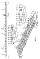
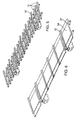
- the support for the following products to be cooked consists of the assembly of three elements which are: feet 1, longitudinal bars 2 which are carried by the feet 1 and crosspieces 3 which are laid across the bars 2.
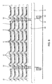
- feet 1 which can be placed either at the ends of the bars 2, as shown in FIG. 1, or at a certain distance from said ends, as shown in Figures 5 and 6.
- the bars 2 are carried by the feet 1, being positioned in housings of them.
- the feet 1 are provided with housings opening on their upper face constituted by notches 10, the bars 2 are then placed in these notches 10.
- Said housings may also not open into the upper face of the feet and be in the form of blind or through holes drilled in the thickness of the foot.
- FIG. 7 shows an alternative embodiment in which the housings are formed by 120 through holes drilled in the feet 101.
- At least two housings 10, 120 in each leg 1, 101 it follows that at least two housings 10, 120 in each leg 1, 101, but there may be have more than two.
- the feet have more than two housings 10, 120, it is possible to constitute a support comprising more than two bars, or have several spacings in order to adapt the spacing between the bars to products that need to be cooked.
- the feet 1 are shaped so that they can be stacked on top of each other so as to form vertical stacks of supports comprising as many stages of bars 2 and crosspieces 3 as there are feet 1 stacked on top of each other.
- the products to be cooked 4 which, in the example shown in Figure 8, are interlocking tiles.
- the support composed by an assembly of feet 1, bars 2, crosspieces 3 bearing products 4 can be placed on the floor 50 of a wagon 5, fitted with wheels 51, rolling on rails 52.
- the implementation of the supports according to the invention makes it possible to constitute stacks supports with as many floors as desired and adapt the height of stacking in the oven section, or use only one support when using a single-layer oven having a low passage section.
- the assemblies of three elements according to the invention form assemblies which are manipulable at one time by known manipulation means.
- gripping means 11 can be, as shown, a part projecting in the middle of the height of a foot 1, this projecting part also being able to be well placed at the base or at the top of the foot 1.
- this projecting part instead of a part in projection we can practice in the mass of the foot a recess in which can penetrate a finger carried by handling tongs.
- FIGS. 9 to 11 illustrate different alternative embodiments of the feet 1.
- the feet shown in Figure 9 are those of Figures 1 to 7.
- the notches 10 have a section which is a semicircle and are arranged on both sides of each foot 1 so that when the feet 1 are placed one on the other, the notches 10 of the upper face of a foot 1 form with the notches 10 of the lower face of the foot 1, which is placed on it, a cylinder in which is fitted the cylindrical bar 2.
- the feet 1 each have five notches 10 on each of their faces, upper and lower. This therefore spares five cylindrical housings so that one can have up to five bars 2 on these feet.
- these five housings will be used to have fewer than five bars so as to adapt the spacing between said bars to the dimensions of the products to be cooked, shown by way of example in FIG. 10, an arrangement using three bars 2.
- each bar 2 is located in two notches 10 formed one in the lower foot 1, the other in the upper foot 1, the feet 1 are held in position against any lateral sliding.
- the notch 10 can also be constituted by a groove having a depth greater than the outside diameter of the bars 2 of so that the bars 2 of a lower leg 1 no longer project into the notches 10 of the upper foot 1 and no longer constitute stops preventing lateral sliding stacked feet.
- the invention is not limited to the case where the bars 2 are of circular section as well as the bottoms of the notches 10: as illustrated in FIGS. 12 and 13, the bars 2 can have any desired section such as square, triangular or else rectangular or even polygonal.
- each leg 1 has, at the bottom of the notch 10, which receives the bar 2, a additional notch 110 which receives a collar 20 whose section corresponds to that of the additional notch 110 in order to accommodate it.
- the notch 110 is slightly larger than the collar 21 to absorb the effects of heat expansion.
- the sleepers 3 are simply placed on the bars 2 and can have any suitable form to effectively support the products 4 to be cooked, they constitute the laying plan of the products to be cooked and are shaped so as to provide the supports needed for each type of product.
- the crosspieces 31 and 32 are U-section bars which include at least one notch 30 which is housed on the upper part of a bar 2, the notch 30 having a shape corresponding to that of said bar 2.
- each cross member 31 and 32 does not have that a single notch 30 which engages on a bar 2, the cross 31/32 resting on the other side flat on the other bar so that it can slide slightly on it in case of expansion due to heat.
- the cross members 32 of FIG. 4 have a greater height than that of the cross members 31 of Figure 3 which allows better positioning of the tiles 4 as seen on the figure 6.
- the crosspieces 3 may not be bars but be plates 34 as this is shown in Figure 6.
- These trays 34 can, as seen in the Figure 6, have a section corresponding to that of the bars 31 and be fixed to their end to a bar 32.
- the invention is not limited to this form particular of tray 34, the important thing being that each tray comprises at least a notch 30 adapted to engage on a bar 2 for its positioning.
- the crosspieces 131 and 132 are of different shapes. These crosspieces 131, 132 can be arranged on the bars 102 being more or less separated from each other so as to be positioned at best depending on the products to be cooked.
- the cross member 132 arranged to the left of a cross member or plate 131 may be further from it than that which is placed to the right of said plate 131 so as to allow passage to a wall extending vertically downwards from the product to be cooked.
- the sleepers being placed on the bars, it's easy to move them relative to them to reposition them and thus adapt the support to the shape of the product to be cooked.
- crosspieces 3 it is still possible to provide for the use of crosspieces 3 by turning them around of one of their three axes.
- the adaptation of the support installation plan to the products to be cooked is carried out in selecting the crosspieces presenting the supports adapted to the products to be cooked and by positioning on the bars with the correct orientation and spacing.
- We can at this effect either keep the sleepers previously used by spreading them apart or bringing them together, possibly after having made them revolve around one of their three axes X, Y, Z in order to position them in such a way that their face faces the top shows the supports adapted to the products to be cooked. It is also possible to replace the sleepers with other sleepers with the necessary supports.
- Figures 20 to 23 show by way of nonlimiting examples different variants of making sleepers 3 and / or plates 34.
- the cross member 3 intended to rest on three bars, has a central notch 30 and rests flat on each side on the other two bars 2.
- the cross-member 3 is similar to those of FIGS. 1 to 6 but, the bars 2 being of square section, the notch 30 is also of square section.
- the bars 2 being of square section as on Figure 21, the two sides 33 of the square section notch 30 may constitute internal (fig. 22) or external (fig. 23) stops.
- the different elements feet 1, bars 2 and crosspieces 3 are made of materials refractory or fire resistant.
- the crosspieces 3 are made of cordierite, silicon carbide or even steel; the bars 2 of refractory material with high mechanical strength such as silicon carbide ; the feet 1 may be of lesser refractory material quality therefore cheaper.
Landscapes
- Engineering & Computer Science (AREA)
- Mechanical Engineering (AREA)
- General Engineering & Computer Science (AREA)
- Cookers (AREA)
- Furnace Charging Or Discharging (AREA)
- Baking, Grill, Roasting (AREA)
Claims (15)
- Träger für Produkte, die in das Innere eines Brennofens verbracht werden sollen, wobei der Träger durch das Zusammenfügen von drei Elementen gebildet wird, nämlich von Füßen (1, 101), von Längsstäben (2, 102), die von den Füßen (1, 101) getragen werden, und von Querstangen (3), die auf den Stäben (2, 102) in Querrichtung zu diesen angeordnet sind und dazu dienen, die zu brennenden Produkte (4) zu tragen, dadurch gekennzeichnet, daß die Füße (1, 101) aufeinander stapelbar ausgebildet sind, so daß die Träger einzeln oder in Stapeln verwendet werden können.
- Träger nach Anspruch 1, dadurch gekennzeichnet, daß das Zusammenfügen von drei Elementen eine Einheit bildet, die von Handhabungsmitteln in einem einzigen Vorgang handhabbar ist.
- Träger nach Anspruch 1 oder nach Anspruch 2, dadurch gekennzeichnet, daß die Querstangen (3) die Aufstellebene für die zu brennenden Produkte (4) bilden, wobei diese Querstangen so ausgebildet sind, daß sie die für verschiedene Arten von Produkten nötigen Stützen bilden, und daß die Anpassung der Aufstellebene des Trägers an die zu brennenden Produkte dadurch erfolgt, daß die Querstangen (3) gewählt werden, welche die für die zu brennenden Produkte angepaßten Stützen bilden, und daß sie in geeigneter Ausrichtung und geeignetem Abstand auf den Stäben (2) positioniert werden.
- Träger nach einem der vorhergehenden Ansprüche, dadurch gekennzeichnet, daß die Stäbe (2, 102) von den Füßen (1, 101) getragen werden, wobei sie in Lagerstellen (10, 120) derselben angeordnet sind.
- Träger nach Anspruch 4, dadurch gekennzeichnet, daß die Lagerstellen (10) Lagerstellen sind, die an der Oberseite der Füße (1) münden und von Ausnehmungen (10) gebildet sind.
- Träger nach Anspruch 4, dadurch gekennzeichnet, daß die Lagerstellen (120) Löcher sind, die in die Dicke des Fußes (101) eingebracht sind.
- Träger nach einem der vorhergehenden Ansprüche, dadurch gekennzeichnet, daß die Querstangen (3) Stege (31, 32, 132) oder Platten (34, 131) sein können.
- Träger nach einem der vorhergehenden Ansprüche, dadurch gekennzeichnet, daß jeder Fuß (1) Greifmittel (11) umfaßt.
- Träger nach einem der Ansprüche 1 bis 5, dadurch gekennzeichnet, daß die Füße (1) gleichzeitig an ihrer Oberseite wie auch an ihrer Unterseite Ausnehmungen aufweisen.
- Träger nach Anspruch 9, dadurch gekennzeichnet, daß diese Ausnehmungen eine Tiefe aufweisen, die dergestalt ist, daß die auf einem Fuß (1) angeordneten Stäbe (2) von der Oberfläche des Fußes (1) nach oben überstehen und in die entsprechenden Ausnehmungen (10) des Fußes (1), der auf den vorhergehenden gestellt ist, eingelassen sind.
- Träger nach einem der Ansprüche 1 bis 10, dadurch gekennzeichnet, daß die Füße (1) zusätzliche Mittel umfassen, die verhindern, daß sie seitlich oder in Längsrichtung aufeinander gleiten.
- Träger nach Anspruch 11, bei dem die zusätzlichen Mittel Vorsprünge (13, 15) sind, die in zusätzliche Ausnehmungen (14, 16) mit entsprechenden Formen eingreifen, welche an und in den Füßen (1) ausgebildet sind.
- Träger nach einem der Ansprüche 1 bis 12, dadurch gekennzeichnet, daß die Stäbe (2) und die Füße (1) Mittel umfassen, welche verhindern, daß die Stäbe (2) auf den Füßen (1) gleiten.
- Träger nach Anspruch 11, dadurch gekennzeichnet, daß die Mittel durch eine zusätzliche am Boden der Ausnehmungen (10) ausgebildete Ausnehmung (110) gebildet sind, wobei die Stäbe (2) mit Bünden (20) versehen sind, deren Querschnitt dem der zusätzlichen Ausnehmungen (110) entspricht.
- Träger nach einem der Ansprüche 1 bis 14, dadurch gekennzeichnet, daß die Querstangen (3) jeweils mit mindestens einer Ausnehmung (30) versehen sind, die mit einem Stab (2) in Eingriff steht.
Applications Claiming Priority (2)
| Application Number | Priority Date | Filing Date | Title |
|---|---|---|---|
| FR9807742A FR2780149B1 (fr) | 1998-06-19 | 1998-06-19 | Perfectionnements aux dispositifs de support de produits dans les fours de cuisson |
| FR9807742 | 1998-06-19 |
Publications (2)
| Publication Number | Publication Date |
|---|---|
| EP0965809A1 EP0965809A1 (de) | 1999-12-22 |
| EP0965809B1 true EP0965809B1 (de) | 2004-10-06 |
Family
ID=9527587
Family Applications (1)
| Application Number | Title | Priority Date | Filing Date |
|---|---|---|---|
| EP19990401506 Expired - Lifetime EP0965809B1 (de) | 1998-06-19 | 1999-06-18 | Stützvorrichtung für Produkte in einem Brennofen |
Country Status (3)
| Country | Link |
|---|---|
| EP (1) | EP0965809B1 (de) |
| DE (1) | DE69920809T2 (de) |
| FR (1) | FR2780149B1 (de) |
Cited By (4)
| Publication number | Priority date | Publication date | Assignee | Title |
|---|---|---|---|---|
| WO2006081971A1 (de) * | 2005-02-07 | 2006-08-10 | Saint-Gobain Industriekeramik Rödental GmbH | Brennhilfsmittel für brennwagenaufbauten und feuerfestzustellungen und verfahren dessen herstellung |
| DE202012103521U1 (de) | 2012-09-14 | 2012-10-02 | Imerys Kiln Furniture Hungary | Brennofenausstattungsaufbau |
| EP2631583A1 (de) | 2012-02-24 | 2013-08-28 | Imerys Kiln Furniture Hungary Ltd. | Feuerfeste Brennofenkassetten und -Baugruppe |
| EP4060271A1 (de) | 2021-03-19 | 2022-09-21 | ImerTech SAS | Brennhilfsmittel |
Families Citing this family (5)
| Publication number | Priority date | Publication date | Assignee | Title |
|---|---|---|---|---|
| DE10154086A1 (de) * | 2001-11-02 | 2003-05-15 | Eisenmann Kg Maschbau | Brennhilfsmittel zum Brennen von Dachziegeln |
| DE10326543B4 (de) * | 2003-06-12 | 2010-05-12 | Saint-Gobain Industriekeramik Rödental GmbH | Variable Vorrichtung zum Tragen und Transportieren von Brenngut beim Brennen von Keramik |
| WO2005087690A2 (en) * | 2004-03-11 | 2005-09-22 | Porvair Plc | Low mass kiln furniture |
| DE102010041353A1 (de) * | 2009-10-19 | 2011-06-16 | Hans Lingl Anlagenbau Und Verfahrenstechnik Gmbh & Co. Kg | Aufnahmegerüst zum Aufnehmen von Formlingen und Tunnelofenwagen |
| DE102010054205B4 (de) * | 2010-12-11 | 2012-08-09 | Schunk Ingenieurkeramik Gmbh | Brennhilfsmittel |
Family Cites Families (9)
| Publication number | Priority date | Publication date | Assignee | Title |
|---|---|---|---|---|
| US2543549A (en) * | 1948-10-30 | 1951-02-27 | Norton Co | Refractory support for ware in a tunnel kiln |
| GB1324882A (en) * | 1970-10-24 | 1973-07-25 | Acme Marls Ltd | Kiln cars |
| DE2749569C2 (de) * | 1977-11-05 | 1986-06-26 | Norbert Dr. 5410 Höhr-Grenzhausen Steuler | Brennhilfsmittelbesatz für das einlagige Brennen keramischer Formlinge |
| DE2939437A1 (de) * | 1979-09-28 | 1981-04-16 | Annawerk Keramische Betriebe GmbH, 8633 Rödental | Brennwagenaufbau |
| US4300881A (en) * | 1980-02-01 | 1981-11-17 | Salviata Impianti S.P.A. | Truck or the like for conveying ceramic articles through a kiln |
| DE3123896C2 (de) * | 1981-06-16 | 1985-12-12 | Adolf A. Fleischmann Inh. Werner Fleischmann, 6000 Frankfurt | Tunnelofenwagen |
| DE3519612A1 (de) * | 1985-05-31 | 1986-12-04 | Hutschenreuther Ag, 8672 Selb | Einrichtung zum brennen von keramischen formteilen, insbesondere porzellangeschirrteilen |
| DE9301095U1 (de) * | 1993-01-27 | 1993-04-01 | Heimsoth Verwaltungen GmbH & Co. KG Beteiligungsgesellschaft, 3200 Hildesheim | Wagenzwischenbau für Förderwagen für Tunnelöfen für den Brand grobkeramischer Teile |
| DE4322099C1 (de) * | 1993-07-02 | 1994-12-15 | Riedhammer Gmbh Co Kg | Brennregal |
-
1998
- 1998-06-19 FR FR9807742A patent/FR2780149B1/fr not_active Expired - Fee Related
-
1999
- 1999-06-18 EP EP19990401506 patent/EP0965809B1/de not_active Expired - Lifetime
- 1999-06-18 DE DE69920809T patent/DE69920809T2/de not_active Expired - Lifetime
Cited By (6)
| Publication number | Priority date | Publication date | Assignee | Title |
|---|---|---|---|---|
| WO2006081971A1 (de) * | 2005-02-07 | 2006-08-10 | Saint-Gobain Industriekeramik Rödental GmbH | Brennhilfsmittel für brennwagenaufbauten und feuerfestzustellungen und verfahren dessen herstellung |
| EP2631583A1 (de) | 2012-02-24 | 2013-08-28 | Imerys Kiln Furniture Hungary Ltd. | Feuerfeste Brennofenkassetten und -Baugruppe |
| WO2013124433A1 (en) | 2012-02-24 | 2013-08-29 | Imerys Kiln Furniture Hungary Ltd. | Kiln furniture cassettes and assembly |
| DE202012103521U1 (de) | 2012-09-14 | 2012-10-02 | Imerys Kiln Furniture Hungary | Brennofenausstattungsaufbau |
| EP4060271A1 (de) | 2021-03-19 | 2022-09-21 | ImerTech SAS | Brennhilfsmittel |
| WO2022194978A1 (en) | 2021-03-19 | 2022-09-22 | Imertech Sas | Kiln furniture |
Also Published As
| Publication number | Publication date |
|---|---|
| FR2780149A1 (fr) | 1999-12-24 |
| DE69920809T2 (de) | 2006-03-02 |
| DE69920809D1 (de) | 2004-11-11 |
| FR2780149B1 (fr) | 2000-09-08 |
| EP0965809A1 (de) | 1999-12-22 |
Similar Documents
| Publication | Publication Date | Title |
|---|---|---|
| EP0965809B1 (de) | Stützvorrichtung für Produkte in einem Brennofen | |
| EP2001780B1 (de) | Hubdeck für palettiervorrichtung | |
| EP2219962B1 (de) | Lade- und entladevorrichtung für förderwagen | |
| FR2544058A1 (fr) | Module(s) de garniture pour chariot de four | |
| FR2676082A1 (fr) | Systeme portant modulaire pour coffrage de dalles, procede et coffrage faisant application d'un tel systeme. | |
| EP0463983B1 (de) | Stapelbare Behältereinheiten, die Nahrungsmittel während ihres Kochvorgangs enthalten | |
| EP1190953B1 (de) | Kunststoffpallette | |
| FR2564303A1 (fr) | Rayonnage reglable | |
| EP0048645B1 (de) | Elektrisch beheizter Ofen mit geringer thermischer Trägheit | |
| EP0838416B1 (de) | Halter für keramische Produkte | |
| FR2599341A1 (fr) | Supports et recipients associes de chargement d'objets | |
| FR2649785A1 (fr) | Support pour materiel a cuire en ceramique | |
| FR2725507A1 (fr) | Barre porteuse et superstructure pour une table de cuisson de produits en ceramique utilisant cette barre porteuse | |
| EP0706492A1 (de) | Pendelartige lagereinrichtung | |
| FR2972613A1 (fr) | Tablette demontable, etagere equipee d'une telle tablette et procede d'assemblage d'une tablette. | |
| FR2523079A3 (fr) | Plate-forme avec elements incorpores pour le transport et/ou le levage de plateaux utilises dans la construction d'echafaudages | |
| FR2649588A1 (fr) | Chargeur-dechargeur automatique pour fours de panification | |
| BE494649A (de) | ||
| FR2528799A1 (fr) | Palette de manutention a elements separables | |
| EP0728429A1 (de) | Kippsicherer Schubladenschrank | |
| FR2889924A1 (fr) | Pietement demontable pour le support de plateau | |
| FR3069424B1 (fr) | Table demontable et pliable equipee d'un systeme de cuisson | |
| FR2496054A1 (fr) | Palette de manutention | |
| FR2601335A1 (fr) | Caisse palette demontable | |
| EP1801023A1 (de) | Lagerungsbehälter mit Schubladen |
Legal Events
| Date | Code | Title | Description |
|---|---|---|---|
| PUAI | Public reference made under article 153(3) epc to a published international application that has entered the european phase |
Free format text: ORIGINAL CODE: 0009012 |
|
| AK | Designated contracting states |
Kind code of ref document: A1 Designated state(s): BE DE FR GB NL |
|
| AX | Request for extension of the european patent |
Free format text: AL;LT;LV;MK;RO;SI |
|
| 17P | Request for examination filed |
Effective date: 20000330 |
|
| AKX | Designation fees paid |
Free format text: BE DE FR GB NL |
|
| 17Q | First examination report despatched |
Effective date: 20030326 |
|
| GRAP | Despatch of communication of intention to grant a patent |
Free format text: ORIGINAL CODE: EPIDOSNIGR1 |
|
| GRAS | Grant fee paid |
Free format text: ORIGINAL CODE: EPIDOSNIGR3 |
|
| GRAA | (expected) grant |
Free format text: ORIGINAL CODE: 0009210 |
|
| AK | Designated contracting states |
Kind code of ref document: B1 Designated state(s): BE DE FR GB NL |
|
| PG25 | Lapsed in a contracting state [announced via postgrant information from national office to epo] |
Ref country code: NL Free format text: LAPSE BECAUSE OF FAILURE TO SUBMIT A TRANSLATION OF THE DESCRIPTION OR TO PAY THE FEE WITHIN THE PRESCRIBED TIME-LIMIT Effective date: 20041006 Ref country code: GB Free format text: LAPSE BECAUSE OF FAILURE TO SUBMIT A TRANSLATION OF THE DESCRIPTION OR TO PAY THE FEE WITHIN THE PRESCRIBED TIME-LIMIT Effective date: 20041006 |
|
| REG | Reference to a national code |
Ref country code: GB Ref legal event code: FG4D Free format text: NOT ENGLISH |
|
| REF | Corresponds to: |
Ref document number: 69920809 Country of ref document: DE Date of ref document: 20041111 Kind code of ref document: P |
|
| NLV1 | Nl: lapsed or annulled due to failure to fulfill the requirements of art. 29p and 29m of the patents act | ||
| GBV | Gb: ep patent (uk) treated as always having been void in accordance with gb section 77(7)/1977 [no translation filed] |
Effective date: 20041006 |
|
| PG25 | Lapsed in a contracting state [announced via postgrant information from national office to epo] |
Ref country code: BE Free format text: LAPSE BECAUSE OF NON-PAYMENT OF DUE FEES Effective date: 20050630 |
|
| PLBE | No opposition filed within time limit |
Free format text: ORIGINAL CODE: 0009261 |
|
| STAA | Information on the status of an ep patent application or granted ep patent |
Free format text: STATUS: NO OPPOSITION FILED WITHIN TIME LIMIT |
|
| 26N | No opposition filed |
Effective date: 20050707 |
|
| BERE | Be: lapsed |
Owner name: *CERIC Effective date: 20050630 |
|
| REG | Reference to a national code |
Ref country code: FR Ref legal event code: TP Owner name: CERIC TECHNOLOGIES, FR Effective date: 20120802 |
|
| REG | Reference to a national code |
Ref country code: DE Ref legal event code: R082 Ref document number: 69920809 Country of ref document: DE Representative=s name: PATENTANWAELTE GEYER, FEHNERS & PARTNER MBB, DE Effective date: 20121115 Ref country code: DE Ref legal event code: R082 Ref document number: 69920809 Country of ref document: DE Representative=s name: GEYER, FEHNERS & PARTNER (G.B.R.), DE Effective date: 20121115 Ref country code: DE Ref legal event code: R081 Ref document number: 69920809 Country of ref document: DE Owner name: CERIC TECHNOLOGIES, FR Free format text: FORMER OWNER: CERIC, PARIS, FR Effective date: 20121115 |
|
| REG | Reference to a national code |
Ref country code: FR Ref legal event code: PLFP Year of fee payment: 18 |
|
| PGFP | Annual fee paid to national office [announced via postgrant information from national office to epo] |
Ref country code: DE Payment date: 20160621 Year of fee payment: 18 |
|
| PGFP | Annual fee paid to national office [announced via postgrant information from national office to epo] |
Ref country code: FR Payment date: 20160627 Year of fee payment: 18 |
|
| REG | Reference to a national code |
Ref country code: DE Ref legal event code: R119 Ref document number: 69920809 Country of ref document: DE |
|
| REG | Reference to a national code |
Ref country code: FR Ref legal event code: ST Effective date: 20180228 |
|
| PG25 | Lapsed in a contracting state [announced via postgrant information from national office to epo] |
Ref country code: DE Free format text: LAPSE BECAUSE OF NON-PAYMENT OF DUE FEES Effective date: 20180103 |
|
| PG25 | Lapsed in a contracting state [announced via postgrant information from national office to epo] |
Ref country code: FR Free format text: LAPSE BECAUSE OF NON-PAYMENT OF DUE FEES Effective date: 20170630 |