EP0965973A1 - Korrekturkreislauf für dargestellte sich bewegende bilder - Google Patents
Korrekturkreislauf für dargestellte sich bewegende bilder Download PDFInfo
- Publication number
- EP0965973A1 EP0965973A1 EP98905754A EP98905754A EP0965973A1 EP 0965973 A1 EP0965973 A1 EP 0965973A1 EP 98905754 A EP98905754 A EP 98905754A EP 98905754 A EP98905754 A EP 98905754A EP 0965973 A1 EP0965973 A1 EP 0965973A1
- Authority
- EP
- European Patent Office
- Prior art keywords
- motion vector
- correlation value
- blocks
- detected
- moving image
- Prior art date
- Legal status (The legal status is an assumption and is not a legal conclusion. Google has not performed a legal analysis and makes no representation as to the accuracy of the status listed.)
- Granted
Links
Images








Classifications
-
- G—PHYSICS
- G09—EDUCATION; CRYPTOGRAPHY; DISPLAY; ADVERTISING; SEALS
- G09G—ARRANGEMENTS OR CIRCUITS FOR CONTROL OF INDICATING DEVICES USING STATIC MEANS TO PRESENT VARIABLE INFORMATION
- G09G3/00—Control arrangements or circuits, of interest only in connection with visual indicators other than cathode-ray tubes
- G09G3/20—Control arrangements or circuits, of interest only in connection with visual indicators other than cathode-ray tubes for presentation of an assembly of a number of characters, e.g. a page, by composing the assembly by combination of individual elements arranged in a matrix no fixed position being assigned to or needed to be assigned to the individual characters or partial characters
- G09G3/22—Control arrangements or circuits, of interest only in connection with visual indicators other than cathode-ray tubes for presentation of an assembly of a number of characters, e.g. a page, by composing the assembly by combination of individual elements arranged in a matrix no fixed position being assigned to or needed to be assigned to the individual characters or partial characters using controlled light sources
- G09G3/28—Control arrangements or circuits, of interest only in connection with visual indicators other than cathode-ray tubes for presentation of an assembly of a number of characters, e.g. a page, by composing the assembly by combination of individual elements arranged in a matrix no fixed position being assigned to or needed to be assigned to the individual characters or partial characters using controlled light sources using luminous gas-discharge panels, e.g. plasma panels
- G09G3/288—Control arrangements or circuits, of interest only in connection with visual indicators other than cathode-ray tubes for presentation of an assembly of a number of characters, e.g. a page, by composing the assembly by combination of individual elements arranged in a matrix no fixed position being assigned to or needed to be assigned to the individual characters or partial characters using controlled light sources using luminous gas-discharge panels, e.g. plasma panels using AC panels
- G09G3/296—Driving circuits for producing the waveforms applied to the driving electrodes
-
- G—PHYSICS
- G09—EDUCATION; CRYPTOGRAPHY; DISPLAY; ADVERTISING; SEALS
- G09G—ARRANGEMENTS OR CIRCUITS FOR CONTROL OF INDICATING DEVICES USING STATIC MEANS TO PRESENT VARIABLE INFORMATION
- G09G3/00—Control arrangements or circuits, of interest only in connection with visual indicators other than cathode-ray tubes
- G09G3/20—Control arrangements or circuits, of interest only in connection with visual indicators other than cathode-ray tubes for presentation of an assembly of a number of characters, e.g. a page, by composing the assembly by combination of individual elements arranged in a matrix no fixed position being assigned to or needed to be assigned to the individual characters or partial characters
- G09G3/2007—Display of intermediate tones
- G09G3/2018—Display of intermediate tones by time modulation using two or more time intervals
- G09G3/2022—Display of intermediate tones by time modulation using two or more time intervals using sub-frames
-
- G—PHYSICS
- G09—EDUCATION; CRYPTOGRAPHY; DISPLAY; ADVERTISING; SEALS
- G09G—ARRANGEMENTS OR CIRCUITS FOR CONTROL OF INDICATING DEVICES USING STATIC MEANS TO PRESENT VARIABLE INFORMATION
- G09G3/00—Control arrangements or circuits, of interest only in connection with visual indicators other than cathode-ray tubes
- G09G3/20—Control arrangements or circuits, of interest only in connection with visual indicators other than cathode-ray tubes for presentation of an assembly of a number of characters, e.g. a page, by composing the assembly by combination of individual elements arranged in a matrix no fixed position being assigned to or needed to be assigned to the individual characters or partial characters
- G09G3/22—Control arrangements or circuits, of interest only in connection with visual indicators other than cathode-ray tubes for presentation of an assembly of a number of characters, e.g. a page, by composing the assembly by combination of individual elements arranged in a matrix no fixed position being assigned to or needed to be assigned to the individual characters or partial characters using controlled light sources
- G09G3/28—Control arrangements or circuits, of interest only in connection with visual indicators other than cathode-ray tubes for presentation of an assembly of a number of characters, e.g. a page, by composing the assembly by combination of individual elements arranged in a matrix no fixed position being assigned to or needed to be assigned to the individual characters or partial characters using controlled light sources using luminous gas-discharge panels, e.g. plasma panels
- G09G3/288—Control arrangements or circuits, of interest only in connection with visual indicators other than cathode-ray tubes for presentation of an assembly of a number of characters, e.g. a page, by composing the assembly by combination of individual elements arranged in a matrix no fixed position being assigned to or needed to be assigned to the individual characters or partial characters using controlled light sources using luminous gas-discharge panels, e.g. plasma panels using AC panels
- G09G3/291—Control arrangements or circuits, of interest only in connection with visual indicators other than cathode-ray tubes for presentation of an assembly of a number of characters, e.g. a page, by composing the assembly by combination of individual elements arranged in a matrix no fixed position being assigned to or needed to be assigned to the individual characters or partial characters using controlled light sources using luminous gas-discharge panels, e.g. plasma panels using AC panels controlling the gas discharge to control a cell condition, e.g. by means of specific pulse shapes
-
- G—PHYSICS
- G09—EDUCATION; CRYPTOGRAPHY; DISPLAY; ADVERTISING; SEALS
- G09G—ARRANGEMENTS OR CIRCUITS FOR CONTROL OF INDICATING DEVICES USING STATIC MEANS TO PRESENT VARIABLE INFORMATION
- G09G2320/00—Control of display operating conditions
- G09G2320/02—Improving the quality of display appearance
- G09G2320/0261—Improving the quality of display appearance in the context of movement of objects on the screen or movement of the observer relative to the screen
-
- G—PHYSICS
- G09—EDUCATION; CRYPTOGRAPHY; DISPLAY; ADVERTISING; SEALS
- G09G—ARRANGEMENTS OR CIRCUITS FOR CONTROL OF INDICATING DEVICES USING STATIC MEANS TO PRESENT VARIABLE INFORMATION
- G09G2320/00—Control of display operating conditions
- G09G2320/02—Improving the quality of display appearance
- G09G2320/0266—Reduction of sub-frame artefacts
-
- G—PHYSICS
- G09—EDUCATION; CRYPTOGRAPHY; DISPLAY; ADVERTISING; SEALS
- G09G—ARRANGEMENTS OR CIRCUITS FOR CONTROL OF INDICATING DEVICES USING STATIC MEANS TO PRESENT VARIABLE INFORMATION
- G09G2320/00—Control of display operating conditions
- G09G2320/10—Special adaptations of display systems for operation with variable images
- G09G2320/106—Determination of movement vectors or equivalent parameters within the image
-
- G—PHYSICS
- G09—EDUCATION; CRYPTOGRAPHY; DISPLAY; ADVERTISING; SEALS
- G09G—ARRANGEMENTS OR CIRCUITS FOR CONTROL OF INDICATING DEVICES USING STATIC MEANS TO PRESENT VARIABLE INFORMATION
- G09G3/00—Control arrangements or circuits, of interest only in connection with visual indicators other than cathode-ray tubes
- G09G3/20—Control arrangements or circuits, of interest only in connection with visual indicators other than cathode-ray tubes for presentation of an assembly of a number of characters, e.g. a page, by composing the assembly by combination of individual elements arranged in a matrix no fixed position being assigned to or needed to be assigned to the individual characters or partial characters
- G09G3/22—Control arrangements or circuits, of interest only in connection with visual indicators other than cathode-ray tubes for presentation of an assembly of a number of characters, e.g. a page, by composing the assembly by combination of individual elements arranged in a matrix no fixed position being assigned to or needed to be assigned to the individual characters or partial characters using controlled light sources
- G09G3/28—Control arrangements or circuits, of interest only in connection with visual indicators other than cathode-ray tubes for presentation of an assembly of a number of characters, e.g. a page, by composing the assembly by combination of individual elements arranged in a matrix no fixed position being assigned to or needed to be assigned to the individual characters or partial characters using controlled light sources using luminous gas-discharge panels, e.g. plasma panels
- G09G3/2803—Display of gradations
Definitions
- This invention relates to a moving image correcting circuit of a display device that displays a multitonal image by time-sharing one frame into plural subfields (or subframes) and emitting the subfields corresponding to the luminance level of input image signal.
- the display devices using PDP Pasma Display Panel
- LCD Liquid Crystal Panel
- the drive method of this PDP is a direct drive by digitalized image input signal.
- the luminance tone as emitted from panel face depends therefore on the number of bits of the signal to be processed.
- the PDP may roughly be divided into AC and DC type methods whose fundamental characteristics differ from each other.
- any AC type PDP sufficient characteristics have been grasped as far as is concerned its luminance and service life.
- 64-tone display was the maximum reported from trial manufacture level.
- ADS subfield method Address/Display Separation type drive method
- Figures 1(a) and (b) show the exemplary drive sequence and drive waveform of the PDP used in this ADS subfield method with 8 bits and 256 tones.
- one frame is composed of eight subfields SF1, SF2, SF3, SF4, SF5, SF6, SF7, and SF8 whose relative ratios of luminance are 1, 2, 4, 8, 16, 32, 64, and 128 respectively. Combination of this luminance of eight screens enables a display in 256 tones.
- the respective subfields are composed of the address duration that writes one screen of refreshed data and the sustaining duration that defines the luminance level of these subfields.
- the address duration a wall charge is formed initially at each pixel simultaneously over all the screens, and then the sustaining pulses are given to all the screens for display.
- the brightness of the subfield is proportional to the number of sustaining pulses to be set to the predetermined luminance. Two hundred and fifty-six tones display is thus actualized.
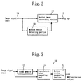
- the foregoing display unit of address/display separation type drive method was conventionally provided with such a moving image correcting circuit as shown in Figure 2 in order to reduce the visual display deviation resulting from the display of a moving image.
- the moving image correcting circuit shown in Figure 2 comprised the moving image correcting portion 11 and the motion vector detecting portion 10, which in turn consisted, as shown in Figure 3, of the frame memory 12, correlation value operation part 13 and motion vector generating portion 14.
- the respective components act as follows.
- the frame memory 12 makes an image signal by one frame before the current frame picture (referred to as "preceding frame picture").
- the correlation value operation part 13 sequentially seeks after the correlation values (differential values) of the image signal for all the blocks in the detection area of the motion vectors in the preceding frame, referring to The block forming the subject of the current frame picture (the block consisting of a single or plural pixels, 2 ⁇ 2 pixels, for example).
- the motion vector generating portion 14 generates a displacement vector (a signal representing displacement direction and displacement amount) whose starting point and end point are the block position of preceding frame picture where the correlation value is minimal and the origin of motion vector (the block position of the preceding frame picture at a position corresponding to the block of current frame picture) respectively.
- the motion vector generating portion 14 generates this displacement vector as a motion vector of the block forming the subject.
- the image signal as input into the input terminal 15 was corrected on the basis of the detected value of the motion vector detecting portion 10 (namely, the motion vector).
- the image signal thus corrected was output to the PDP (not shown) through the intermediary of the output terminal 16.
- the moving image was thus corrected by correcting the display position of each subfield for the pixels in the subject block.
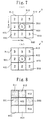
- the detection area KR of the motion vector of the preceding frame picture has 25 blocks (5 ⁇ 5 blocks) and that the image (pictorial image) that was at the position of The block ZB51 in this detection area KR has now displaced to the position of the block GB33 in the current frame picture. Further, it is assumed that the blocks ZB11 to ZB65 of the preceding frame picture and the blocks GB11 to GB55 of the current frame picture are formed respectively with 2 ⁇ 2 pixels (or as many dots).
- A1, B1, C1, and D1 represent the luminance levels of the pixels forming the respective blocks of preceding frame picture ZB11 to ZB55 as shown in Figure 5(a), while A2, B2, C2, and D2 indicate the luminance levels of the pixels forming the subject block of current frame picture GB33 as shown in Figure 5(b).
- the motion vector generating portion 14 compares the plural correlation values as obtained in the correlation value operation part 13 with each other, and generates, as shown by the thick lines in Figure 4(b), the displacement vector MV whose starting and end points are respectively the position of the block ZB51 of preceding frame picture where the correlation value is minimal and origin of motion vector (block ZB33 position of preceding frame picture corresponding to the block GB33 in the current frame picture).
- the motion vector generating portion 14 then outputs this vector MV as the motion picture of the subject block GB33.
- the motion vectors can be obtained in a similar fashion also for other blocks (for instance, GB11 or GB55) of the current frame picture, when the motion vector detection area KR of the preceding frame picture embraces 25 peripheral blocks (5 ⁇ 5 blocks) centered around the corresponding origin (for example, positions of the blocks of preceding frame picture ZB11 or ZB55 corresponding to the block GB11 or GB55).
- the block position corresponding to the least correlation value does not always coincide with the starting point (or end point) of the displacement vector if any dispersion appears in the correlation value as obtained from the correlation value operation part 13 due, for example, to the noise in the input image signal or to the fluctuation of the input image signal, there were some cases where erroneous motion vectors were detected that differed from the intrinsic motion vectors representing the notion as viewed by humans.
- a correlation value, out of those in Figure 6, for the block ZB65 near the origin of preceding frame picture (block ZB55 position at vertical vector "0" and horizontal vector "0") changes from intrinsic "0" to "10” and the correlation value for the block ZB82 away from the origin changes from intrinsic "20" to "9” both by reason of noise, fluctuation or the like.
- the motion vector generating portion 14 compares the correlation values shown in Figure 6 with each other, and generates and outputs a motion vector whose starting point and end point are respectively the block ZB82 position corresponding to the least correlation value "9" and the origin. Namely, as shown in Figure 6, not the motion vector with horizontal vector "0" and vertical vector 1 with, as the starting point, the block B65 position corresponding to the intrinsic least correlation value "0", but an erroneous motion vector with horizontal vector "-3" and vertical vector "3" with the block B82 as starting point is output.
- the conventional art was therefore problematical in that the moving image correction conversely worsens the picture quality if the moving image is corrected by the moving image correcting portion 11 based on the foregoing erroneous motion vector.
- the moving image can be corrected on the basis of a correct detected values "2" or "3" while for any pixels in the central block B22 the moving image correction is committed on the basis of erroneously detected value "5".
- the prior art was problematical in that ironically the correction of moving image caused the picture quality to be degraded.
- the moving image correction intended for enhancing the picture quality may be performed for the pixels in the six blocks B11, B12, B21, B23, B31, and B32 from which the notion vectors have been detected, but no moving image can be corrected for any pixels in the three blocks B13, B22, and B33 from which no motion vector has been detected.
- the result was the same; that is, such a moving image correction was problematical in that it conversely caused the degradation of the picture quality.
- This invention made in the light of the foregoing problematical points, is intended to prevent the picture quality from being worsened due to the noise in or fluctuation of input image signal if the moving image is corrected to reduce any visual display deviation engendered when displaying the moving image in a display device that displays multitonal image by time-sharing one frame into plural subfields and emitting the subfields corresponding to the luminance level of input image signal.
- the moving image correction circuit by the first invention is characterized in that in a display device that displays multitonal image by time-sharing one frame into plural subfields and emitting the subfields corresponding to the luminance level of input image signal, said circuit has a motion vector detecting portion that detects the motion vector in a single frame or inter-frame blocks (for instance, 2 ⁇ 2 pixels) on the basis of said input image signal, and the moving image correcting portion that outputs, to said display device, the signal which corrected the display position of respective subfields for the pixels in the blocks, based on the detected value of said motion vector detecting portion, wherein said motion vector detecting portion has a correlation value operation portion that operates the correlation values of image signal corresponding to all the blocks in the detection area of preceding frame picture on the basis of the blocks forming the subject of current frame picture, a least correlation value detecting portion that detects the least correlation value S1 having the highest correlation among the plural correlation values as obtained in said correlation value operation portion, a multiplier that multiplies this least correlation value S1 by a
- the least correlation value S1 (9 for example) detected from the least correlation value detecting portion is that corresponding to an erroneous block away from the origin, and the intrinsic least correlation value ("0" for example) corresponding to a block near the origin changes into a correlation value S1a (for example, "10") larger than S1.
- a correlation value S1a for example, "10" larger than S1.
- an erroneous motion vector is detected whose starting and end points are the block position corresponding to the least correlation value S1 and the origin respectively. In our case, however, such an erroneous motion vector is kept from being detected by the first invention.
- the correlation value converting portion converts the correlation value not larger than the multiplied value K ⁇ S1 (1.5 ⁇ S1 for example) from among the correlation values obtained in the correlation value operation part, into a set correlation value S2 not larger than S1 ("0" for example) to include the correlation value S1a before the conversion in the least correlation value (S2) forming the subject of detection.
- the motion vector generating portion detects the correlation value corresponding to the block the nearest to the origin from among plural least correlation values (corresponding to the correlation value S1a before the conversion), and generates a displacement vector whose starting point and end point are the block position corresponding to said detected correlation value and the origin respectively and outputs this displacement vector as a motion vector.
- This configuration may prevent the notion vector detecting portion to output an erroneous motion vector due to noise, fluctuation or the like, avoiding thus the degradation of picture quality in the correction of moving image in the moving image correcting portion.
- the moving image correction circuit by the second invention is characterized in that in a display device that displays multitonal image by time-sharing one frame into plural subfields and emitting the subfields corresponding to the luminance level of input image signal, said circuit has a motion vector detecting portion that detects the motion vector in a single frame or inter-frame blocks based on input image signal, a majority processing portion that seeks after the most numerous identical detect values from among the detection values detected by the motion vector detecting portion for all the blocks within the set range S including the subject block, and a moving image correcting portion that outputs, to said display device, the signal which corrected the display position of respective subfields of the pixels in the subject block, based on the detected value as obtained in said majority processing portion.
- the motion vector detecting portion detects the displacement direction (upward on the screen, for example) and displacement amount (5 dots or 5 pixels per frame) of inter-frame blocks (that is, detects the motion vector).
- the majority processing portion seeks after the most numerous, identical detect values from among the detected values by the motion vector detecting portion for the blocks within the set range S.
- the moving image correcting portion corrects the input image signal based on the detected value as obtained in the majority processing portion and outputs this signal as corrected to the display device. This configuration allows the majority processing to eliminate uneven motion vector even if the motion vector detecting portion outputs any erroneous motion vector due to noise, fluctuation or the like, thereby keeping the picture quality from being degraded in the moving image correcting process.
- the moving image correction circuit by the third invention is characterized in that in a display device that displays multitonal image by time-sharing one frame into plural subfields and emitting the subfields corresponding to the luminance level of input image signal, said circuit has a motion vector detecting portion that detects the motion vector in a single frame or inter-frame blocks on the basis of input image signal, a majority processing portion that seeks after the most numerous identical detect values from among the values detected by the motion vector detecting portion for all the blocks within the set range S including the subject block, a vertical/horizontal/oblique detecting portion that detects whether or not the blocks having identical detect values by the motion vector detecting portion have been continuously arranged vertically, horizontally or obliquely within the set range S including the subject block and outputs the identical detect values when detecting, a selector that selects the detected values as output from this vertical/horizontal/oblique detecting portion if there is any detection output therefrom and selects the detect values obtained in the majority processing portion if there is no such detection output, and
- this configuration namely the third invention allows the majority processing to eliminate uneven motion vector even if the motion vector detecting portion outputs any erroneous motion vector due to noise, fluctuation or the like, thereby keeping the picture quality from being degraded in the moving image correcting process.
- this third invention is so designed that, when an image with one respective vertical, horizontal and oblique lines moves toward predetermined direction, the detected values of this image with vertical, horizontal and oblique lines are made to supersede, by means of the detection output of the vertical/horizontal/oblique detecting portion, the detection values obtained by majority processing, an exact moving image correction can be performed deep in detail into the image.
- the moving image correction circuit by the fourth invention is characterized in that in a display device that displays multitonal image by time-sharing one frame into plural subfields and emitting the subfields corresponding to the luminance level of input image signal, said circuit has a motion vector detecting portion that detects the motion vector in a single frame or inter-frame blocks on the basis of input image signal, a motion vector delaying portion that seeks after the motion vector of each block in the set range S consisting of the subject block and peripheral blocks by delaying the detection value of said motion vector detecting portion, a motion vector counting portion that counts up the number of the blocks detected as having motion vectors in all the blocks within the set range S, a count comparing portion that compares if the count by said motion vector counting portion is superior to the set value or not, a motion vector embedding portion that outputs the motion vector based on the output from the motion vector delaying portion and that of the count comparing portion, and a moving image correcting portion that outputs to the display device the signal which corrected the display position of each subfield of
- the motion vector embedding portion When there is no motion vector of subject block as obtained from the motion vector delaying portion and the count comparing portion is sending out a comparison signal, the motion vector embedding portion outputs, as the motion vector, and to moving correcting portion the motion vector of the blocks detected as having the motion vector in the set range S. That is, when the number of the blocks detected as having motion vector in the set range S is superior to the set value, the motion vector of the subject block is embedded (substituted)with the motion vector of the blocks detected as having motion vector even if there is no motion vector of subject block.
- each subfield may be corrected for the pixels in the subject block on the basis of the motion vector as embedded by the motion vector embedding portion, even if the motion vector has not been detected by reason of noise, fluctuation or the like despite the very existence of the motion vector.
- the dispersion in the subject block and peripheral blocks being thus annihilated, the moving image can be corrected without deteriorating the picture quality.
- the moving image correcting portion by the 5th, 6th and 7th inventions replacing the motion vector detecting portion, one of the components of the foregoing 2nd, 3rd, and 4th inventions, with the motion vector detecting portion, one of the components by the first invention, it is prevented that any erroneous motion vector be output from the upstream motion vector detecting portion.
- the downstream circuit keeps any erroneous motion vector from entering the moving image correcting portion even when an erroneous motion vector may come out of the motion vector detecting portion. This configuration makes it possible to keep, with higher precision, the picture quality from being degraded in the correction of moving image by the moving image correcting portion.
- Figure 9 shows an embodiment of the moving image correcting circuit by the first invention, wherein like reference characters designate like or corresponding parts in Figures 2 and 3.
- 10A represents the motion vector detecting portion
- 11 is the moving image correcting portion
- said motion vector detecting portion 10A comprises the frame memory 12, the correlation value operation part 13, the least correlation value detecting portion 20, the multiplier 22, the delaying portion 24, the correlation value converting portion 26, and the motion vector generating portion 14.
- Said frame memory 12 delays by one frame the image signal as input into the input terminal 15 to generate the image signal of the preceding frame picture, which is output to the correlation value operation part 13.
- Said correlation value operation part 13 sequentially seeks after and outputs the correlation values (differential values) with all the blocks (for example, ZB11 to ZB55 In Figure 4(a)) within the detection area KR of the motion vector in the preceding frame picture referring to the block GB forming the subject of the current frame picture (for example, GB33 in Figure 4 (b)).
- Said least correlation value detecting portion 20 detects the least correlation value S1 with highest correlation from among the plural correlation values obtained at said correlation value operation part 13, and outputs the least correlation value S1 thus obtained.
- Said multiplier 22 multiplies, by a preset coefficient 1.5 (case where the coefficient K is 1.5), the least correlation value S1 as detected in said least correlation value detecting portion 20, and outputs the product 1.5 ⁇ S1.
- Said delaying portion 24 delays the correlation value obtained in said correlation value operation part 13 by the time required for the signal processing of said least correlation value detecting portion 20 and multiplier 22.
- Said motion vector generating portion 14 compares the correlation values output from said correlation value converting portion 26 with each other, detects the correlation value corresponding to the block nearest to the origin (for example, ZB33 position in Figure 4 (a)) from among the plural set correlation values "0", generates a displacement vector whose starting point and end point are the block position corresponding to said detected correlation value and the origin, respectively, and outputs this vector to the output terminal 16 as the motion vector of the block to be detected of the current frame picture.
- the correlation value corresponding to the block nearest to the origin for example, ZB33 position in Figure 4 (a)
- Said moving image correcting portion 11 corrects the image signal as input into said input terminal 15 on the basis of the motion vector as detected in said motion vector detecting portion 10A, and outputs this image signal to the PDP side through the intermediary of the output terminal 16.
- the detection area KR of the preceding frame be 81 blocks centered on the origin (position of block ZB55 of preceding frame corresponding to block GB55 forming the subject of detection of the current frame) as was the case shown in Figure 6. It is also assumed that the correlation values as obtained in the correlation value operation part 13 for the blocks ZB11 to ZB99 in the detection area KR have changed into the correlation value data 1 (same value as in Figure 6) as shown in Figure 10(a) due to noise, fluctuation or the like.
- This configuration allows therefore to prevent any output of erroneous motion vector from the motion vector detecting portion 10A due to noise, fluctuation or the like, avoiding thereby the degradation of the picture quality by the moving image correction at the moving image correcting portion.
- the set correlation value S2 converted by the correlation values converting portion be "0"
- the set correlation value S2 may be any value if only it is less than the least correlation value S1 as detected in the least correlation value detecting portion ("5" for example).
- the coefficient K by which the multiplier multiplies the least correlation value S1 ("9" for example) be 1.5 this invention is not limited to any such embodiment.
- the coefficient may be any value if only it is greater than 1 so that the intrinsic least correlation value (for example, correlation value "10") should fall within the range forming the subject of the detection of motion vector despite the dispersion in correlation value due to noise, fluctuation or the like.
- this invention is not limited to such an embodiment.
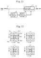
- Figure 11 shows an embodiment of the moving image correcting circuit by the second invention, wherein like reference characters designate like or corresponding parts as in Figure 2.
- the numeral 10 represents a motion vector detecting portion, 11 a moving image correcting portion, and 30 a majority processing portion.
- Said majority processing portion 30 seeks after and outputs the most numerous, identical detection values from among the detect values by said motion vector detecting portion 10 for the blocks in the set range S including the subject block. As shown in Figure 7(a), for instance, if the detected value of the subject block B22 is "5", the detected value of peripheral blocks B11, B12, B21, B31, and B32 is “2" and the detected value of B13, B23, and B33 is "3", then the blocks of detected value "2" is the most numerous (5). So this detected value "2" is determined as such and output by the majority processing portion 30.
- said moving image correcting portion 11 Based on the detected value ("2" for example) output from said majority processing portion 30, said moving image correcting portion 11 corrects the display positions of the respective subfields (SFn to SF1) of the pixels in the subject block B22 as input into said input terminal 15, and outputs the correction signal to the PDP through the intermediary of the output terminal 16.
- the set range S embraces nine blocks including the block B22, the subject of processing and its peripheral blocks B11 to B33 (except B22) and that a part of the detection values of the motion vector detecting portion 10 has been changed from the intrinsic value into differing one due to noise, fluctuation or the like.
- the detected value of the motion vector of the subject block B22 has changed from its intrinsic value ("2" for example) into "5" and that the peripheral blocks B11 to B33 (except B22) have not been subjected to the influence of any noise nor fluctuation.
- the detected values "5", “2", and “3” as shown in Figure 7(a) represent the displacement amount (5, 2, and 3 dots/frame, for example) in certain direction (upward for example). From this it results that the detected values "-5", “-2" and “-3" (not shown) represent the displacement amount (5, 2, and 3 dots/frame, for example) in opposite direction.
- the majority processing may eliminate the protruded value ("5"), preventing thereby the degradation of the picture quality in the moving image correction.
- the majority processing portion has been so designed that the most numerous, identical detection values ("2" in the case of Figure 7(a)) are searched for from among the detected values by the motion vector detecting portion for the blocks within the set range S, but this invention may not be limited to such a configuration.
- This invention is also applicable to any cases where the blocks in the set range S are ranked, and when there are numerous, identical detection values as determined by majority processing method, the detection value of higher rank may be sought after from among these plural, identical detection values.
- the foregoing embodiment has been so designed as to prevent the degradation of picture quality of the moving image in the moving image correction by eliminating any protruded value through the majority processing (including the cases with and without ranking). However, we have such exceptional cases where the majority processing is not enough to solve the problem.
- the detected value of the motion vector detecting portion 10 becomes "3" both for the subject block and the peripheral blocks B12, and B32, and "0" for any other peripheral blocks B11, B13, B21, B23,B31, and B33, as shown in Figure 12(a).
- Figure 13 shows an embodiment of the moving image correcting portion by the third invention, contrived to solve the problems such as above.
- Like reference characters designate like or corresponding parts as in Figure 11.
- the numeral 32 represents a vertical/horizontal/oblique detecting portion and 34 a selector.
- Said vertical/horizontal/oblique detecting portion 32 determines if the blocks with identical detected values by the motion vector detecting portion 10 have been continuously arranged either vertically, horizontally or obliquely including the subject block B22 within the set range S, and outputs, when detecting, said identical detected values (for example, the detected value of the subject block B22).
- said selectors 34 selects the detection value "sv” (motion vector) as output by this vertical/horizontal/oblique detecting portion 32, and if the same "se” does not exist (L level for example), it selects the detected value "tv” (motion vector) as obtained from the majority processing portion 30.
- the detected values by the motion vector detecting portion 10 differ from those shown in Figures 14(a), (b), (c) and (d) (for example, They do not correspond to the image of vertical, horizontal, and oblique lines), there is no detection output "se" of the vertical/horizontal/oblique detecting portion 32 (L level for example). Therefore, the selector 34 will output the detected value "tv” as output by the majority processing portion 30, while the moving image correcting portion 11 corrects the display positions of subfields SFn to SF1 (n in number) for the pixels in the subject block B22, based on the detection value "tv" chosen at the selector 34.
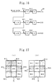
- Figure 15 illustrates an embodiment of the moving image correcting circuit by the fourth invention, in which like reference characters designate the like or corresponding parts as in Figure 2.
- the numeral 10 represents the motion vector detecting portion, 11 the moving image correcting portion, 40 the motion vector delaying portion, 42 the motion vector counting portion, 44 the count comparing portion, and 46 the motion vector embedding portion.
- the 1-dot delaying element D comprises D-FF (Flip-Flop)
- 1-line delaying element LM comprises line memory.
- said motion vector counting portion 42 Based on the motion vector output from said motion vector delaying portion 40, said motion vector counting portion 42 counts up the number of the blocks detected as having motion vectors in all the blocks B11 to B33 within the set range S to output this count K.
- Said count comparing portion 44 compares the count K by said motion vector counting portion 42 with the set value Q as input into the set value input terminal 48, and outputs a comparison signal (H-level signal, for example) if K ⁇ Q.
- Said motion vector embedding portion 46 outputs, as the motion vector of the subject block, the motion vector of the block with higher priority from among the blocks detected as having motion vector within the set range S, when said count comparing portion 44 outputs a comparison signal (H-level signal for example) and there is no motion vector of the subject block B22 to be output from said motion vector delaying portion 40 (namely, when the motion vector detecting portion 10 detects no motion vector for the subject block B22), and outputs the motion vector of the subject block B22 to be output from said motion vector delaying portion 40 in any other cases than the above.
- a comparison signal H-level signal for example
- the set range S embraces the nine blocks as shown in Figure 17(a) and that the blocks detected as having the motion vector are B11, B12, B21, B23, B31, and B32 (case of K ⁇ Q) as hatched in the same drawing
- the blocks B11 to B33 (except B22) other than the subject block B22 are ranked beforehand (for example, into a sequential order of: B21, B23, B12, B32, B11, B13, B31, and B33) and the motion vector of subject block with higher rank (block B21 for example) from among the blocks detected as having motion vector B11, B12, B21, B23, B31, and B32 is output as the motion vector of the subject block B22.
- Said moving image correcting portion 11 outputs to the PDP through the output terminal 16 the signal that corrected the display position of the subfields SFn to SF1 (n in number) of each frame of pixels in the subject block, based on the motion vector as output from said motion vector embedding portion 46.
- the signal that corrected the display positions of the subfields SFn to SF1 (n in number) of each frame of pixels in the subject block B22 is output to the PDP through the output terminal 16, based on the motion vector (the motion vector of block B21 for example) as output from said motion vector embedding portion 46.
- the set range S embraces nine blocks consisting of the subject block B22 to be processed and of its peripheral blocks B11 to B33 (except B22) and priority is given beforehand to these peripheral blocks in the sequential order of B21, B23, B12, B32, B11, B13, B31, and B33, and that the set value Q of the count comparing portion 44 is 5.
- this invention may not be understood as to be limited to this sort of embodiment.
- the description was made assuming a case where the set range S comprises the subject block and its eight peripheral blocks (9 in all). But the invention should not be limited to such an embodiment; similar embodiment will be available also for other cases where the set range S comprises n ⁇ m blocks (5 ⁇ 5 blocks for example).
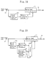
- Figure 18 shows an embodiment of the moving image correcting circuit by the fifth invention, wherein the motion vector detecting portion 10 in the embodiment by the second invention, shown in Figure 11 is replaced by the motion vector detecting portion 10A in the embodiment by the first invention.
- Figure 19 shows an embodiment of the moving image correcting circuit by the sixth invention, wherein the motion vector detecting portion 10 in the embodiment by the third invention, shown in Figure 13 is replaced by the motion vector detecting portion 10A in the embodiment by the first invention.
- Figure 20 shows an embodiment of the moving image correcting circuit by the seventh invention, wherein the motion vector detecting portion 10 in the embodiment by the fourth invention, shown in Figure 15 is replaced by the motion vector detecting portion 10A in the embodiment by the first invention.
- the moving image correcting circuit as shown in Figures 18,19, and 20 keeps any erroneous motion vector from being output from the upstream motion vector detecting portion 10A in such a fashion that no erroneous motion vector should enter the moving image correcting portion in the downstream circuit, even if this motion vector detecting portion 10A outputs any erroneous vector.
- the circuit thus may avoid, with yet a higher accuracy, the degradation of picture quality at the time of the correction of the moving image.
- this invention may be used to protect the picture quality from degrading due to the noise in and fluctuation of the input image signal when correcting the moving image.
Landscapes
- Engineering & Computer Science (AREA)
- Physics & Mathematics (AREA)
- Computer Hardware Design (AREA)
- General Physics & Mathematics (AREA)
- Theoretical Computer Science (AREA)
- Power Engineering (AREA)
- Plasma & Fusion (AREA)
- Control Of Indicators Other Than Cathode Ray Tubes (AREA)
- Control Of Gas Discharge Display Tubes (AREA)
- Compression Or Coding Systems Of Tv Signals (AREA)
Applications Claiming Priority (7)
| Application Number | Priority Date | Filing Date | Title |
|---|---|---|---|
| JP6929597 | 1997-03-06 | ||
| JP06929597A JP4158950B2 (ja) | 1997-03-06 | 1997-03-06 | ディスプレイ装置の動画補正回路 |
| JP9490297 | 1997-03-28 | ||
| JP9094902A JPH10274962A (ja) | 1997-03-28 | 1997-03-28 | ディスプレイ装置の動画補正回路 |
| JP9213954A JPH1145068A (ja) | 1997-07-25 | 1997-07-25 | 動きベクトル検出回路 |
| JP21395497 | 1997-07-25 | ||
| PCT/JP1998/000888 WO1998039764A1 (en) | 1997-03-06 | 1998-03-04 | Moving picture correcting circuit of display |
Publications (3)
| Publication Number | Publication Date |
|---|---|
| EP0965973A1 true EP0965973A1 (de) | 1999-12-22 |
| EP0965973A4 EP0965973A4 (de) | 2000-07-26 |
| EP0965973B1 EP0965973B1 (de) | 2010-07-14 |
Family
ID=27300011
Family Applications (1)
| Application Number | Title | Priority Date | Filing Date |
|---|---|---|---|
| EP98905754A Expired - Lifetime EP0965973B1 (de) | 1997-03-06 | 1998-03-04 | Korrekturkreislauf für dargestellte sich bewegende bilder |
Country Status (8)
| Country | Link |
|---|---|
| US (1) | US6456337B1 (de) |
| EP (1) | EP0965973B1 (de) |
| KR (1) | KR100514615B1 (de) |
| AU (1) | AU732968B2 (de) |
| CA (1) | CA2283330C (de) |
| DE (1) | DE69841762D1 (de) |
| TW (1) | TW394914B (de) |
| WO (1) | WO1998039764A1 (de) |
Families Citing this family (23)
| Publication number | Priority date | Publication date | Assignee | Title |
|---|---|---|---|---|
| WO2001001382A1 (en) * | 1999-06-28 | 2001-01-04 | Koninklijke Philips Electronics N.V. | Subfield-driven display |
| DE10035109B4 (de) * | 1999-07-20 | 2012-03-08 | Lg Information & Communications, Ltd. | Terminal und Verfahren zum Transportieren von Standbildern |
| JP2001197501A (ja) * | 2000-01-07 | 2001-07-19 | Fujitsu Ltd | 動きベクトル探索器及び動きベクトル探索方法並びに動画像符号化装置 |
| US7053874B2 (en) | 2000-09-08 | 2006-05-30 | Semiconductor Energy Laboratory Co., Ltd. | Light emitting device and driving method thereof |
| KR20030027963A (ko) * | 2001-06-21 | 2003-04-07 | 코닌클리케 필립스 일렉트로닉스 엔.브이. | 픽셀들을 처리하기 위한 이미지 처리 유닛 및 방법과이러한 이미지 처리 유닛을 포함하는 이미지 디스플레이장치 |
| SG120889A1 (en) * | 2001-09-28 | 2006-04-26 | Semiconductor Energy Lab | A light emitting device and electronic apparatus using the same |
| SG120888A1 (en) | 2001-09-28 | 2006-04-26 | Semiconductor Energy Lab | A light emitting device and electronic apparatus using the same |
| JP2003330419A (ja) * | 2002-05-15 | 2003-11-19 | Semiconductor Energy Lab Co Ltd | 表示装置 |
| US7307607B2 (en) * | 2002-05-15 | 2007-12-11 | Semiconductor Energy Laboratory Co., Ltd. | Passive matrix light emitting device |
| US20040150594A1 (en) * | 2002-07-25 | 2004-08-05 | Semiconductor Energy Laboratory Co., Ltd. | Display device and drive method therefor |
| JP4077738B2 (ja) | 2003-02-17 | 2008-04-23 | 三星エスディアイ株式会社 | 映像処理回路、映像処理方法及び映像表示装置並びに映像表示方法 |
| US7482629B2 (en) * | 2004-05-21 | 2009-01-27 | Semiconductor Energy Laboratory Co., Ltd. | Display device and electronic device |
| JP4705764B2 (ja) * | 2004-07-14 | 2011-06-22 | 株式会社半導体エネルギー研究所 | ビデオデータ補正回路及び表示装置の制御回路並びにそれを内蔵した表示装置・電子機器 |
| EP1653433B1 (de) * | 2004-10-29 | 2016-02-03 | Semiconductor Energy Laboratory Co., Ltd. | Videodatenkorrekturschaltung, anzeigevorrichtung und elektronische vorrichtung |
| KR20060088419A (ko) * | 2005-02-01 | 2006-08-04 | 삼성전자주식회사 | 디스크 교환시기 표시방법 |
| JP4910645B2 (ja) * | 2006-11-06 | 2012-04-04 | 株式会社日立製作所 | 画像信号処理方法、画像信号処理装置、表示装置 |
| CN101803362A (zh) * | 2007-09-10 | 2010-08-11 | Nxp股份有限公司 | 用于视频图像数据中的运动估计和运动补偿的方法和装置 |
| AT505798B1 (de) * | 2007-09-20 | 2011-12-15 | Naderhirn Michael | Verfahren zur automatischen vermeidung von kollisionen eines objektes mit weiteren objekten |
| JP2010015061A (ja) * | 2008-07-04 | 2010-01-21 | Panasonic Corp | 画像表示装置、集積回路及びコンピュータプログラム |
| JP4780212B2 (ja) * | 2009-03-24 | 2011-09-28 | 富士ゼロックス株式会社 | 画像形成装置及び異常判断プログラム |
| US9113133B2 (en) * | 2012-01-31 | 2015-08-18 | Prime Image Delaware, Inc. | Method and system for detecting a vertical cut in a video signal for the purpose of time alteration |
| CN102592130B (zh) * | 2012-02-16 | 2013-11-06 | 浙江大学 | 一种针对水下显微视频的目标识别系统及其视频编码方法 |
| CN102592290A (zh) * | 2012-02-16 | 2012-07-18 | 浙江大学 | 一种针对水下显微视频的运动目标区域检测方法 |
Family Cites Families (11)
| Publication number | Priority date | Publication date | Assignee | Title |
|---|---|---|---|---|
| GB2248361B (en) * | 1990-09-28 | 1994-06-01 | Sony Broadcast & Communication | Motion dependent video signal processing |
| GB2266023B (en) * | 1992-03-31 | 1995-09-06 | Sony Broadcast & Communication | Motion dependent video signal processing |
| US6160900A (en) * | 1994-02-04 | 2000-12-12 | Canon Kabushiki Kaisha | Method and apparatus for reducing the processing time required in motion vector detection |
| JPH089340A (ja) | 1994-06-24 | 1996-01-12 | Mitsubishi Electric Corp | 動きベクトル検出装置及び動きベクトル検出方法 |
| US6178265B1 (en) * | 1994-09-22 | 2001-01-23 | Intel Corporation | Method and apparatus for motion vector compression |
| GB2296401B (en) * | 1994-10-04 | 1998-10-14 | Kenneth Stanley Jones | Improved 'majority' filter |
| JP3711378B2 (ja) * | 1995-02-06 | 2005-11-02 | 株式会社日立製作所 | 中間調表示方法及び中間調表示装置 |
| US5903313A (en) * | 1995-04-18 | 1999-05-11 | Advanced Micro Devices, Inc. | Method and apparatus for adaptively performing motion compensation in a video processing apparatus |
| JP3631868B2 (ja) * | 1996-12-20 | 2005-03-23 | 株式会社東芝 | 動きベクトル検出装置および方法 |
| JP3226020B2 (ja) * | 1997-05-28 | 2001-11-05 | 日本電気株式会社 | 動きベクトル検出装置 |
| US6081553A (en) * | 1998-04-06 | 2000-06-27 | Hewlett Packard Company | Block-matching motion estimation technique for video compression of noisy source signals |
-
1998
- 1998-03-04 AU AU61198/98A patent/AU732968B2/en not_active Ceased
- 1998-03-04 KR KR10-1999-7008113A patent/KR100514615B1/ko not_active Expired - Fee Related
- 1998-03-04 DE DE69841762T patent/DE69841762D1/de not_active Expired - Lifetime
- 1998-03-04 CA CA002283330A patent/CA2283330C/en not_active Expired - Fee Related
- 1998-03-04 US US09/380,357 patent/US6456337B1/en not_active Expired - Lifetime
- 1998-03-04 EP EP98905754A patent/EP0965973B1/de not_active Expired - Lifetime
- 1998-03-04 WO PCT/JP1998/000888 patent/WO1998039764A1/ja not_active Ceased
- 1998-03-05 TW TW087103241A patent/TW394914B/zh not_active IP Right Cessation
Also Published As
| Publication number | Publication date |
|---|---|
| EP0965973B1 (de) | 2010-07-14 |
| CA2283330A1 (en) | 1998-09-11 |
| KR100514615B1 (ko) | 2005-09-15 |
| CA2283330C (en) | 2004-10-26 |
| TW394914B (en) | 2000-06-21 |
| AU6119898A (en) | 1998-09-22 |
| EP0965973A4 (de) | 2000-07-26 |
| AU732968B2 (en) | 2001-05-03 |
| KR20000076027A (ko) | 2000-12-26 |
| WO1998039764A1 (en) | 1998-09-11 |
| DE69841762D1 (de) | 2010-08-26 |
| US6456337B1 (en) | 2002-09-24 |
Similar Documents
| Publication | Publication Date | Title |
|---|---|---|
| CA2283330C (en) | Moving picture correcting circuit of display | |
| CA2286354C (en) | Dynamic image correction method and dynamic image correction circuit for display | |
| US8941778B2 (en) | Video display apparatus | |
| KR100889429B1 (ko) | 플라즈마 디스플레이 장치 및 그 구동 방법 | |
| US7605780B2 (en) | Display apparatus and control method thereof | |
| US7142175B2 (en) | Method and apparatus for displaying grayscale of plasma display panel | |
| US6348930B1 (en) | Motion vector processing circuit | |
| CN1681292A (zh) | 显示装置 | |
| KR100702240B1 (ko) | 디스플레이장치 및 그 제어방법 | |
| JP3482764B2 (ja) | ディスプレイ装置の動画補正用動き量検出回路 | |
| US20050093780A1 (en) | Method and apparatus for displaying an image on a plasma display panel | |
| JPH1185100A (ja) | 映像信号の表示装置 | |
| JPH09138666A (ja) | 表示装置の動画補正方法及び動画補正装置 | |
| JP2008256986A (ja) | 画像処理方法及びこれを用いた画像表示装置 | |
| JP4158950B2 (ja) | ディスプレイ装置の動画補正回路 | |
| JPH10274962A (ja) | ディスプレイ装置の動画補正回路 | |
| JPH1145068A (ja) | 動きベクトル検出回路 | |
| JPH11288240A (ja) | 表示装置の駆動方法及び回路 | |
| US20110279468A1 (en) | Image processing apparatus and image display apparatus | |
| JP2001042819A (ja) | 階調表示方法、及び階調表示装置 | |
| JPH10149137A (ja) | 動画補正用動きベクトル検出回路 | |
| JP2011139124A (ja) | 動きベクトル生成装置、表示装置、集積回路、動きベクトル生成プログラムおよび動きベクトル生成方法 | |
| JP2006146172A (ja) | 多階調表示装置における画質劣化低減方法 | |
| Ohara et al. | A reduction method of dynamic false contour utilizing the frame‐rate‐control method with suppression of the side effect on PDPs | |
| JP2010091795A (ja) | 動画像表示装置及び動画像表示方法 |
Legal Events
| Date | Code | Title | Description |
|---|---|---|---|
| PUAI | Public reference made under article 153(3) epc to a published international application that has entered the european phase |
Free format text: ORIGINAL CODE: 0009012 |
|
| 17P | Request for examination filed |
Effective date: 19991001 |
|
| AK | Designated contracting states |
Kind code of ref document: A1 Designated state(s): DE ES FR GB IT NL |
|
| A4 | Supplementary search report drawn up and despatched |
Effective date: 20000609 |
|
| AK | Designated contracting states |
Kind code of ref document: A4 Designated state(s): DE ES FR GB IT NL |
|
| RIC1 | Information provided on ipc code assigned before grant |
Free format text: 7G 09G 3/28 A, 7G 06T 7/20 B, 7H 04N 5/14 B |
|
| 17Q | First examination report despatched |
Effective date: 20071214 |
|
| RAP1 | Party data changed (applicant data changed or rights of an application transferred) |
Owner name: CANON KABUSHIKI KAISHA |
|
| GRAP | Despatch of communication of intention to grant a patent |
Free format text: ORIGINAL CODE: EPIDOSNIGR1 |
|
| GRAS | Grant fee paid |
Free format text: ORIGINAL CODE: EPIDOSNIGR3 |
|
| GRAA | (expected) grant |
Free format text: ORIGINAL CODE: 0009210 |
|
| AK | Designated contracting states |
Kind code of ref document: B1 Designated state(s): DE ES FR GB IT NL |
|
| REG | Reference to a national code |
Ref country code: GB Ref legal event code: FG4D |
|
| REF | Corresponds to: |
Ref document number: 69841762 Country of ref document: DE Date of ref document: 20100826 Kind code of ref document: P |
|
| REG | Reference to a national code |
Ref country code: NL Ref legal event code: VDEP Effective date: 20100714 |
|
| PG25 | Lapsed in a contracting state [announced via postgrant information from national office to epo] |
Ref country code: NL Free format text: LAPSE BECAUSE OF FAILURE TO SUBMIT A TRANSLATION OF THE DESCRIPTION OR TO PAY THE FEE WITHIN THE PRESCRIBED TIME-LIMIT Effective date: 20100714 |
|
| PLBE | No opposition filed within time limit |
Free format text: ORIGINAL CODE: 0009261 |
|
| STAA | Information on the status of an ep patent application or granted ep patent |
Free format text: STATUS: NO OPPOSITION FILED WITHIN TIME LIMIT |
|
| PG25 | Lapsed in a contracting state [announced via postgrant information from national office to epo] |
Ref country code: IT Free format text: LAPSE BECAUSE OF FAILURE TO SUBMIT A TRANSLATION OF THE DESCRIPTION OR TO PAY THE FEE WITHIN THE PRESCRIBED TIME-LIMIT Effective date: 20100714 |
|
| 26N | No opposition filed |
Effective date: 20110415 |
|
| PG25 | Lapsed in a contracting state [announced via postgrant information from national office to epo] |
Ref country code: ES Free format text: LAPSE BECAUSE OF FAILURE TO SUBMIT A TRANSLATION OF THE DESCRIPTION OR TO PAY THE FEE WITHIN THE PRESCRIBED TIME-LIMIT Effective date: 20101025 |
|
| REG | Reference to a national code |
Ref country code: DE Ref legal event code: R097 Ref document number: 69841762 Country of ref document: DE Effective date: 20110415 |
|
| REG | Reference to a national code |
Ref country code: FR Ref legal event code: ST Effective date: 20111130 |
|
| PG25 | Lapsed in a contracting state [announced via postgrant information from national office to epo] |
Ref country code: FR Free format text: LAPSE BECAUSE OF NON-PAYMENT OF DUE FEES Effective date: 20110331 |
|
| PGFP | Annual fee paid to national office [announced via postgrant information from national office to epo] |
Ref country code: DE Payment date: 20140331 Year of fee payment: 17 |
|
| PGFP | Annual fee paid to national office [announced via postgrant information from national office to epo] |
Ref country code: GB Payment date: 20140318 Year of fee payment: 17 |
|
| REG | Reference to a national code |
Ref country code: DE Ref legal event code: R119 Ref document number: 69841762 Country of ref document: DE |
|
| GBPC | Gb: european patent ceased through non-payment of renewal fee |
Effective date: 20150304 |
|
| PG25 | Lapsed in a contracting state [announced via postgrant information from national office to epo] |
Ref country code: GB Free format text: LAPSE BECAUSE OF NON-PAYMENT OF DUE FEES Effective date: 20150304 Ref country code: DE Free format text: LAPSE BECAUSE OF NON-PAYMENT OF DUE FEES Effective date: 20151001 |