EP0965983B1 - Vorrichtungen zur optischen Abtastung, zur Spurverfolgung und zum Abspielen von Platten - Google Patents
Vorrichtungen zur optischen Abtastung, zur Spurverfolgung und zum Abspielen von Platten Download PDFInfo
- Publication number
- EP0965983B1 EP0965983B1 EP99302261A EP99302261A EP0965983B1 EP 0965983 B1 EP0965983 B1 EP 0965983B1 EP 99302261 A EP99302261 A EP 99302261A EP 99302261 A EP99302261 A EP 99302261A EP 0965983 B1 EP0965983 B1 EP 0965983B1
- Authority
- EP
- European Patent Office
- Prior art keywords
- light
- light beam
- optical
- light receiving
- region
- Prior art date
- Legal status (The legal status is an assumption and is not a legal conclusion. Google has not performed a legal analysis and makes no representation as to the accuracy of the status listed.)
- Expired - Lifetime
Links
Images









Classifications
-
- G—PHYSICS
- G11—INFORMATION STORAGE
- G11B—INFORMATION STORAGE BASED ON RELATIVE MOVEMENT BETWEEN RECORD CARRIER AND TRANSDUCER
- G11B7/00—Recording or reproducing by optical means, e.g. recording using a thermal beam of optical radiation by modifying optical properties or the physical structure, reproducing using an optical beam at lower power by sensing optical properties; Record carriers therefor
- G11B7/12—Heads, e.g. forming of the optical beam spot or modulation of the optical beam
- G11B7/13—Optical detectors therefor
- G11B7/131—Arrangement of detectors in a multiple array
-
- G—PHYSICS
- G11—INFORMATION STORAGE
- G11B—INFORMATION STORAGE BASED ON RELATIVE MOVEMENT BETWEEN RECORD CARRIER AND TRANSDUCER
- G11B7/00—Recording or reproducing by optical means, e.g. recording using a thermal beam of optical radiation by modifying optical properties or the physical structure, reproducing using an optical beam at lower power by sensing optical properties; Record carriers therefor
- G11B7/08—Disposition or mounting of heads or light sources relatively to record carriers
- G11B7/09—Disposition or mounting of heads or light sources relatively to record carriers with provision for moving the light beam or focus plane for the purpose of maintaining alignment of the light beam relative to the record carrier during transducing operation, e.g. to compensate for surface irregularities of the latter or for track following
-
- G—PHYSICS
- G11—INFORMATION STORAGE
- G11B—INFORMATION STORAGE BASED ON RELATIVE MOVEMENT BETWEEN RECORD CARRIER AND TRANSDUCER
- G11B7/00—Recording or reproducing by optical means, e.g. recording using a thermal beam of optical radiation by modifying optical properties or the physical structure, reproducing using an optical beam at lower power by sensing optical properties; Record carriers therefor
- G11B7/08—Disposition or mounting of heads or light sources relatively to record carriers
- G11B7/09—Disposition or mounting of heads or light sources relatively to record carriers with provision for moving the light beam or focus plane for the purpose of maintaining alignment of the light beam relative to the record carrier during transducing operation, e.g. to compensate for surface irregularities of the latter or for track following
- G11B7/094—Methods and circuits for servo offset compensation
-
- G—PHYSICS
- G11—INFORMATION STORAGE
- G11B—INFORMATION STORAGE BASED ON RELATIVE MOVEMENT BETWEEN RECORD CARRIER AND TRANSDUCER
- G11B7/00—Recording or reproducing by optical means, e.g. recording using a thermal beam of optical radiation by modifying optical properties or the physical structure, reproducing using an optical beam at lower power by sensing optical properties; Record carriers therefor
- G11B7/12—Heads, e.g. forming of the optical beam spot or modulation of the optical beam
- G11B7/123—Integrated head arrangements, e.g. with source and detectors mounted on the same substrate
-
- G—PHYSICS
- G11—INFORMATION STORAGE
- G11B—INFORMATION STORAGE BASED ON RELATIVE MOVEMENT BETWEEN RECORD CARRIER AND TRANSDUCER
- G11B7/00—Recording or reproducing by optical means, e.g. recording using a thermal beam of optical radiation by modifying optical properties or the physical structure, reproducing using an optical beam at lower power by sensing optical properties; Record carriers therefor
- G11B7/12—Heads, e.g. forming of the optical beam spot or modulation of the optical beam
- G11B7/135—Means for guiding the beam from the source to the record carrier or from the record carrier to the detector
- G11B7/1353—Diffractive elements, e.g. holograms or gratings
-
- G—PHYSICS
- G11—INFORMATION STORAGE
- G11B—INFORMATION STORAGE BASED ON RELATIVE MOVEMENT BETWEEN RECORD CARRIER AND TRANSDUCER
- G11B7/00—Recording or reproducing by optical means, e.g. recording using a thermal beam of optical radiation by modifying optical properties or the physical structure, reproducing using an optical beam at lower power by sensing optical properties; Record carriers therefor
- G11B7/12—Heads, e.g. forming of the optical beam spot or modulation of the optical beam
- G11B7/135—Means for guiding the beam from the source to the record carrier or from the record carrier to the detector
- G11B7/1359—Single prisms
-
- G—PHYSICS
- G11—INFORMATION STORAGE
- G11B—INFORMATION STORAGE BASED ON RELATIVE MOVEMENT BETWEEN RECORD CARRIER AND TRANSDUCER
- G11B7/00—Recording or reproducing by optical means, e.g. recording using a thermal beam of optical radiation by modifying optical properties or the physical structure, reproducing using an optical beam at lower power by sensing optical properties; Record carriers therefor
- G11B7/12—Heads, e.g. forming of the optical beam spot or modulation of the optical beam
- G11B7/135—Means for guiding the beam from the source to the record carrier or from the record carrier to the detector
- G11B7/1372—Lenses
-
- G—PHYSICS
- G11—INFORMATION STORAGE
- G11B—INFORMATION STORAGE BASED ON RELATIVE MOVEMENT BETWEEN RECORD CARRIER AND TRANSDUCER
- G11B7/00—Recording or reproducing by optical means, e.g. recording using a thermal beam of optical radiation by modifying optical properties or the physical structure, reproducing using an optical beam at lower power by sensing optical properties; Record carriers therefor
- G11B7/12—Heads, e.g. forming of the optical beam spot or modulation of the optical beam
- G11B7/135—Means for guiding the beam from the source to the record carrier or from the record carrier to the detector
- G11B7/1381—Non-lens elements for altering the properties of the beam, e.g. knife edges, slits, filters or stops
-
- G—PHYSICS
- G11—INFORMATION STORAGE
- G11B—INFORMATION STORAGE BASED ON RELATIVE MOVEMENT BETWEEN RECORD CARRIER AND TRANSDUCER
- G11B11/00—Recording on or reproducing from the same record carrier wherein for these two operations the methods are covered by different main groups of groups G11B3/00 - G11B7/00 or by different subgroups of group G11B9/00; Record carriers therefor
- G11B11/10—Recording on or reproducing from the same record carrier wherein for these two operations the methods are covered by different main groups of groups G11B3/00 - G11B7/00 or by different subgroups of group G11B9/00; Record carriers therefor using recording by magnetic means or other means for magnetisation or demagnetisation of a record carrier, e.g. light induced spin magnetisation; Demagnetisation by thermal or stress means in the presence or not of an orienting magnetic field
- G11B11/105—Recording on or reproducing from the same record carrier wherein for these two operations the methods are covered by different main groups of groups G11B3/00 - G11B7/00 or by different subgroups of group G11B9/00; Record carriers therefor using recording by magnetic means or other means for magnetisation or demagnetisation of a record carrier, e.g. light induced spin magnetisation; Demagnetisation by thermal or stress means in the presence or not of an orienting magnetic field using a beam of light or a magnetic field for recording by change of magnetisation and a beam of light for reproducing, i.e. magneto-optical, e.g. light-induced thermomagnetic recording, spin magnetisation recording, Kerr or Faraday effect reproducing
- G11B11/1055—Disposition or mounting of transducers relative to record carriers
- G11B11/10576—Disposition or mounting of transducers relative to record carriers with provision for moving the transducers for maintaining alignment or spacing relative to the carrier
Definitions
- optical disk apparatus which can realize a high precision information reading operation.
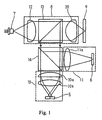
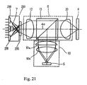
- the beam splitter 122 directs the light path of this reflected beam to a beam splitter 124.
- the focusing system is structured by including the collimator lens 120, beam splitter 122, triangular prism 116 and objective lens 114.
- the amounts of receiving light of both the light receiving section 136a and the light receiving section 136b of the two-divided photodetector 136 is equal. Therefore, there is no relative difference in the amount of receiving light of the light receiving sections 136a, 136b.
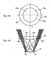
- Fig. 11 is a diagram showing the amount of receiving light passing the regions A to D of the optical element.
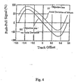
- a change in the amount of incident light is indicated when the focus spot : is moved from track to track when the optical axis of the objective lens 114 is deviated by 200 ⁇ m from the optical axis of the focusing optical system in the direction crossing the track.
- the incident light beam of the optical element 145 and two-divided photodetector 136 exists at the position indicated by a solid line in Fig. 10.
- the amount of light IA indicates the amount of light in the region A.
- the amount of light IB indicates the amount of light in the region B.
- the amount of light IC indicates the amount of light in the region C, and the amount of light ID indicates the amount of light in the region D.
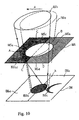
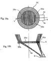
- the amount of receiving light is never added to the light receiving section 6b. Since a part of the light beam passes the flat plate region 195c, the amount of the receiving light of a part of the light beam is added to the light receiving section 6a.
- the amount of receiving light of the light receiving section 6a relatively increases in comparison with the amount of receiving light of the light receiving section 6b. Therefore, the amount of receiving light of the light receiving section 6a increases to correct imbalance in the amounts of receiving light of the light receiving sections 6a, 6b.
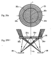
- the fourth diffraction grating 235d changes the direction of the light path of the light beam passing the fourth diffraction grating 235d so that the light beam enters the photodetector 236 arranged in the opposite side of the dividing line L (or optical axis 4a) for the fourth diffraction grating 235d.
Landscapes
- Physics & Mathematics (AREA)
- Optics & Photonics (AREA)
- Optical Recording Or Reproduction (AREA)
- Optical Head (AREA)
Claims (18)
- Optische Vorrichtung zum Decodieren von in einem Ziel (9) gespeicherter Information, mit:einer Lichtquelle (7);einer Kondensorlinse (20), die so angeordnet ist, dass Licht von der Quelle (7) durch sie gelangt, um das Licht in einen Strahl zu formen, der zum Ziel (9) geschickt wird, welches Ziel den Lichtstrahl mit der Information codiert und den codierten Lichtstrahl zu ersten und zweiten Licht empfangenden Sektionen (236, 246; 238, 248) lenkt, undeiner optischen Einrichtung (235, 245), die dafür eingerichtet ist, zu ermöglichen, dass der Lichtstrahl hindurchgeht, um die Verteilung des Lichts in den ersten und zweiten Licht empfangenden Sektionen (236, 246; 238, 248) auszugleichen, falls die optische Achse des Lichtstrahls bezüglich der Licht empfangenden Sektionen verschoben ist, wenn der Lichtstrahl mit dem Ziel (9) ausgerichtet ist;dadurch gekennzeichnet, dass die ersten und zweiten Licht empfangenden Sektionen (236, 246; 238, 248) so angeordnet sind, dass sie voneinander getrennt sind; und
die optische Einrichtung (235, 245) eine erste Fläche (235a, 245a) aufweist, um den Lichtstrahl zu der ersten Licht empfangenden Sektion (236; 246) zu lenken, eine zweite Fläche (235b; 245b), um den lichtstrahl zu der zweiten Licht empfangenden Sektion (238; 248) zu lenken, eine erste Licht lenkende Region (235c, 245c), die der ersten Fläche benachbart ist, um den Lichtstrahl zu der zweiten Licht empfangenden Sektion (238; 248) zu lenken, und eine zweite Licht lenkende Region (235d, 245d), die der zweiten Fläche benachbart ist, um den Lichtstrahl zu der ersten Licht empfangenden Sektion (236; 246) zu lenken. - Optische Vorrichtung nach Anspruch 1, wobei die optische Einrichtung (235, 245) umfasst:ein optisches Element (235; 245), durch das der Lichtstrahl gelangt, bevor er von den ersten und zweiten Licht empfangenden Sektionen empfangen wird, welche optische Einrichtung (235, 245) eine kreisartige Region (235a, 235b; 245a, 245b) aufweist, durch die das Licht gelangen kann, welche kreisartige Region (235a, 235b; 245a, 245b) einen Durchmesser hat, der kleiner oder gleich dem Durchmesser des Lichtstrahls ist,welche kreisartige Region (235a, 235b; 245a, 245b) ferner zumindest erste und zweite Hälften (235a, 235b; 245a, 245b) aufweist, wobei durch die erste Hälfte (235a; 245a) gelangendes Licht in Richtung auf die erste Licht empfangende Sektion (236; 246) gelenkt wird und Licht, das durch die zweite Hälfte (235b; 245b) gelangt, in Richtung auf die zweite Licht empfangende Sektion (238; 248) gelenkt wird,welches optische Element (235; 245) ferner eine erste Licht lenkende Einrichtung (235c; 245c) außerhalb der ersten Hälfte (235a; 245a) der kreisartigen Region (235a, 235b; 245a, 245b) aufweist, die Licht zu der zweiten Licht empfangenden Sektion (238; 248) lenkt, und eine zweite Licht lenkende Einrichtung (235d; 245d) außerhalb der zweiten Hälfte (235b; 245b) der kreisartigen Region (235a, 235b; 245a, 245b), die Licht zu der ersten Licht empfangenden Sektion (236; 246) lenkt.
- Optische Vorrichtung nach Anspruch 2, wobei
die kreisartige Region (235a, 235b; 245a, 245b) kreisförmig ist. - Optische Vorrichtung nach Anspruch 2, wobei
die ersten und zweiten kreisartigen Regionen aus Bögen mit einem Radius geschaffen sind, der größer als die halbe Gesamtbreite der kreisartigen Region ist, und ein Ursprung aus der Mitte der optischen Einrichtung verschoben ist. - Optische Vorrichtung nach Anspruch 2, wobei
die kreisartigen Regionen eine elliptische Kontur aufweisen. - Optische Vorrichtung nach einem der Ansprüche 2 bis 5, wobei
die ersten und zweiten Licht lenkenden Einrichtungen (235c, 245c; 235d, 245d) Beugungsgitter sind. - Optische Vorrichtung nach einem der Ansprüche 2 bis 5, wobei
die ersten und zweiten Licht lenkenden Einrichtungen (235c, 245c; 235d, 245d) Prismen sind. - Optische Vorrichtung nach einem der Ansprüche 2 bis 5, wobei
die ersten und zweiten Licht lenkenden Einrichtungen (235c, 245c; 235d, 245d) kreisförmige Linsen sind. - Optische Vorrichtung nach einem der Ansprüche 2 bis 8, wobei
die ersten und zweiten Hälften dritte und vierte Licht lenkende Einrichtungen sind, welche ersten und zweiten Hälften der ersten und zweiten Licht empfangenden Sektionen auf verschiedenen Seiten der optischen Einrichtung aus der Achse verschoben sind. - Optische Vorrichtung nach Anspruch 9, ferner mit:einer dritten Licht empfangenden Sektion (249), weiche optische Einrichtung ferner eine fünfte Licht lenkende Einrichtung (245e) aufweist, die einen Teil des Lichtstrahls zu der dritten Licht empfangenden Sektion (249) lenkt.
- Optische Vorrichtung nach Anspruch 10, wobei
die dritte Licht empfangende Sektion (249) bezüglich der Achse versetzt ist. - Optische Vorrichtung nach Anspruch 10 oder 11, wobei
die Lichtquelle (7) und die ersten, zweiten und dritten Licht empfangenden Sektionen (246, 248, 249) auf einem einzigen Substrat montiert sind. - Optische Vorrichtung nach einem der Ansprüche 10 bis 12, wobei
das Ziel (9) eine Spur in einem Spurmedium ist, welche ersten und zweiten Licht empfangenden Sektionen (246, 248) ein Spurfolge-Fehlersignal erzeugen und welche dritte Licht empfangende Sektion (249) ein Fokus-Fehlersignal erzeugt - Optische Vorrichtung nach einem der Ansprüche 10 bis 13, wobei
die ersten, zweiten, dritten, vierten und fünften Licht lenkenden Einrichtungen (245a bis 245e) als ein Beugungsgitter aus einer einzigen dünnen Platte geschaffen sind. - Optische Vorrichtung nach einem der Ansprüche 2 bis 14, mit:einer abschirmenden Region in den kreisartigen Regionen.
- Optische Vorrichtung nach Anspruch 15, wobei
die abschirmende Region opak ist. - Optische Vorrichtung nach Anspruch 15, wobei
die abschirmende Region ein Beugungsgitter ist. - Optische Vorrichtung nach einem der Ansprüche 1 bis 9, wobei
die Lichtquelle (7) und die ersten und zweiten Licht empfangenden Sektionen (246, 248) auf einem einzigen Substrat montiert sind.
Applications Claiming Priority (2)
| Application Number | Priority Date | Filing Date | Title |
|---|---|---|---|
| JP16236098 | 1998-06-10 | ||
| JP16236098A JP3422255B2 (ja) | 1998-06-10 | 1998-06-10 | トラッキング装置、及び光ディスク装置 |
Publications (3)
| Publication Number | Publication Date |
|---|---|
| EP0965983A2 EP0965983A2 (de) | 1999-12-22 |
| EP0965983A3 EP0965983A3 (de) | 2001-02-14 |
| EP0965983B1 true EP0965983B1 (de) | 2007-10-31 |
Family
ID=15753096
Family Applications (1)
| Application Number | Title | Priority Date | Filing Date |
|---|---|---|---|
| EP99302261A Expired - Lifetime EP0965983B1 (de) | 1998-06-10 | 1999-03-24 | Vorrichtungen zur optischen Abtastung, zur Spurverfolgung und zum Abspielen von Platten |
Country Status (5)
| Country | Link |
|---|---|
| US (2) | US6407967B1 (de) |
| EP (1) | EP0965983B1 (de) |
| JP (1) | JP3422255B2 (de) |
| KR (1) | KR100350511B1 (de) |
| DE (1) | DE69937427T2 (de) |
Families Citing this family (12)
| Publication number | Priority date | Publication date | Assignee | Title |
|---|---|---|---|---|
| KR100403622B1 (ko) * | 2001-04-12 | 2003-10-30 | 삼성전자주식회사 | 광픽업장치 및 광스폿의 최적 포커싱 방법 |
| JP3782325B2 (ja) * | 2001-07-27 | 2006-06-07 | 株式会社日立製作所 | ディスク駆動装置 |
| JP2003203407A (ja) * | 2001-12-28 | 2003-07-18 | Fujitsu Ltd | 光磁気記録再生装置 |
| JP2004264808A (ja) * | 2003-01-07 | 2004-09-24 | Shinohara Yasuko | 光学顕微鏡および天体望遠鏡の結像方法 |
| DE10330945A1 (de) * | 2003-07-08 | 2005-02-03 | Deutsche Thomson-Brandt Gmbh | Optischer Abtaster mit Mikrooptik zur Strahlkombination |
| JP2005222600A (ja) * | 2004-02-05 | 2005-08-18 | Pioneer Electronic Corp | ディスク挿入排出装置 |
| TWI250301B (en) * | 2004-03-17 | 2006-03-01 | Asia Optical Co Inc | The optical system of laser meter |
| JP3980602B2 (ja) * | 2005-03-02 | 2007-09-26 | シャープ株式会社 | 収差検出装置およびそれを備えた光ピックアップ装置 |
| WO2006118082A1 (ja) * | 2005-04-27 | 2006-11-09 | Matsushita Electric Industrial Co., Ltd. | 光ヘッド装置および光情報処理装置 |
| KR101350988B1 (ko) | 2012-05-16 | 2014-01-15 | 도시바삼성스토리지테크놀러지코리아 주식회사 | 트랙킹 에러신호 생성 방법 및 장치 및 이를 적용한 광정보저장매체 시스템 |
| KR101722536B1 (ko) * | 2016-11-07 | 2017-04-04 | 윤태열 | 레이저 트랙커를 이용한 부품 조립공정 및 그 조립 오차 보정장치 |
| CN114883420A (zh) * | 2022-04-25 | 2022-08-09 | Nano科技(北京)有限公司 | 提高光电探测器高功率工作特性的封装结构及封装方法 |
Family Cites Families (11)
| Publication number | Priority date | Publication date | Assignee | Title |
|---|---|---|---|---|
| JPH0680535B2 (ja) | 1982-08-27 | 1994-10-12 | 株式会社日立製作所 | 情報の記録再生方法 |
| US5231621A (en) * | 1986-09-05 | 1993-07-27 | Canon Kabushiki Kaisha | Focus detector which serves to split off a portion of a detected light beam only when the detected light beam is not refocused at an expected refocus point |
| NL8703001A (nl) | 1986-12-11 | 1988-07-01 | Pioneer Electronic Corp | Een volgfoutsignaalgenerator. |
| DE68923833T2 (de) * | 1988-06-20 | 1996-06-13 | Mitsubishi Electric Corp | Optischer Kopf mit Kippkorrekturservomechanismus. |
| JPH0770073B2 (ja) | 1989-08-04 | 1995-07-31 | 松下電器産業株式会社 | 光学ヘッド |
| US5253236A (en) | 1991-10-03 | 1993-10-12 | International Business Machines Corporation | Optical beam focusing and tracking system for an optical disk information storage device |
| JP2532818B2 (ja) | 1993-02-01 | 1996-09-11 | 松下電器産業株式会社 | 対物レンズおよび光ヘッド装置 |
| JP2942718B2 (ja) | 1994-10-05 | 1999-08-30 | 富士通株式会社 | 光学的情報記録再生装置 |
| JPH08306057A (ja) | 1995-05-11 | 1996-11-22 | Matsushita Electric Ind Co Ltd | 光学ヘッド |
| JP3563210B2 (ja) | 1996-02-14 | 2004-09-08 | 富士通株式会社 | 光ディスク装置用光学装置及び光ディスク装置 |
| KR100375514B1 (ko) * | 1997-10-20 | 2003-11-28 | 삼성전기주식회사 | 광픽업장치 |
-
1998
- 1998-06-10 JP JP16236098A patent/JP3422255B2/ja not_active Expired - Fee Related
- 1998-12-30 US US09/223,656 patent/US6407967B1/en not_active Expired - Fee Related
-
1999
- 1999-01-19 KR KR1019990001422A patent/KR100350511B1/ko not_active Expired - Fee Related
- 1999-03-24 EP EP99302261A patent/EP0965983B1/de not_active Expired - Lifetime
- 1999-03-24 DE DE69937427T patent/DE69937427T2/de not_active Expired - Fee Related
-
2002
- 2002-06-10 US US10/166,187 patent/US20020167885A1/en not_active Abandoned
Also Published As
| Publication number | Publication date |
|---|---|
| JPH11353670A (ja) | 1999-12-24 |
| JP3422255B2 (ja) | 2003-06-30 |
| US20020167885A1 (en) | 2002-11-14 |
| DE69937427T2 (de) | 2008-04-17 |
| EP0965983A3 (de) | 2001-02-14 |
| KR20000005566A (ko) | 2000-01-25 |
| DE69937427D1 (de) | 2007-12-13 |
| EP0965983A2 (de) | 1999-12-22 |
| KR100350511B1 (ko) | 2002-08-28 |
| US6407967B1 (en) | 2002-06-18 |
Similar Documents
| Publication | Publication Date | Title |
|---|---|---|
| EP0539354B1 (de) | Optische Abtastvorrichtung | |
| US5365504A (en) | Optical disk apparatus, and construction of optical disk | |
| EP0418087B1 (de) | Optischer Kopf | |
| US4951274A (en) | Magneto-optical head capable of separating beams for reading recorded information and servo information by use of one optical element | |
| US6324133B1 (en) | Optical recording and reproducing apparatus and optical recording and reproducing method | |
| EP0965983A2 (de) | Vorrichtungen zur optischen Abtastung, zur Spurverfolgung und zum Abspielen von Platten | |
| EP0208538B1 (de) | Optischer Aufnahmekopf mit astigmatischer Fokussierung | |
| US6314068B1 (en) | Optical head device, inclination detection apparatus using the same, and optical information processing apparatus using the same | |
| US5579298A (en) | Optical scanner having symmetry about an oblique divider | |
| US20050094511A1 (en) | Method and device for detecting optical data and reading-writing apparatus for optical data | |
| US6327231B1 (en) | Optical head device with zero-cross point correction | |
| US6418098B1 (en) | Optical head apparatus for reproducing information from an optical recording medium | |
| EP1460623B1 (de) | Optische abnehmervorrichtung | |
| JPH0690817B2 (ja) | 光ピツクアツプ | |
| US5218597A (en) | Optical reading and writing device | |
| JP2003203371A (ja) | 光ディスク装置 | |
| EP0759610A2 (de) | Optische Abtastvorrichtung zur Aufzeichnung/Wiedergabe mit hoher Dichte | |
| JP2629456B2 (ja) | 対物レンズ位置検出装置 | |
| JPS63144423A (ja) | 光ヘツド装置 | |
| JP2005115990A (ja) | 光ピックアップ装置及び光ディスク装置 | |
| JP2545453B2 (ja) | 光学的情報記録再生装置 | |
| JPH0739053Y2 (ja) | 光ヘッド | |
| EP0628955A1 (de) | Optischer Kopf | |
| JPH04205726A (ja) | オフセット除去装置 | |
| JP2005077769A (ja) | 光軸調整装置 |
Legal Events
| Date | Code | Title | Description |
|---|---|---|---|
| PUAI | Public reference made under article 153(3) epc to a published international application that has entered the european phase |
Free format text: ORIGINAL CODE: 0009012 |
|
| AK | Designated contracting states |
Kind code of ref document: A2 Designated state(s): DE FR GB |
|
| AX | Request for extension of the european patent |
Free format text: AL;LT;LV;MK;RO;SI |
|
| PUAL | Search report despatched |
Free format text: ORIGINAL CODE: 0009013 |
|
| AK | Designated contracting states |
Kind code of ref document: A3 Designated state(s): AT BE CH CY DE DK ES FI FR GB GR IE IT LI LU MC NL PT SE |
|
| AX | Request for extension of the european patent |
Free format text: AL;LT;LV;MK;RO;SI |
|
| 17P | Request for examination filed |
Effective date: 20010305 |
|
| AKX | Designation fees paid |
Free format text: DE FR GB |
|
| GRAP | Despatch of communication of intention to grant a patent |
Free format text: ORIGINAL CODE: EPIDOSNIGR1 |
|
| GRAS | Grant fee paid |
Free format text: ORIGINAL CODE: EPIDOSNIGR3 |
|
| GRAA | (expected) grant |
Free format text: ORIGINAL CODE: 0009210 |
|
| AK | Designated contracting states |
Kind code of ref document: B1 Designated state(s): DE FR GB |
|
| REG | Reference to a national code |
Ref country code: GB Ref legal event code: FG4D |
|
| REF | Corresponds to: |
Ref document number: 69937427 Country of ref document: DE Date of ref document: 20071213 Kind code of ref document: P |
|
| PGFP | Annual fee paid to national office [announced via postgrant information from national office to epo] |
Ref country code: GB Payment date: 20080328 Year of fee payment: 10 |
|
| ET | Fr: translation filed | ||
| PGFP | Annual fee paid to national office [announced via postgrant information from national office to epo] |
Ref country code: DE Payment date: 20080408 Year of fee payment: 10 |
|
| REG | Reference to a national code |
Ref country code: GB Ref legal event code: 732E |
|
| PLBE | No opposition filed within time limit |
Free format text: ORIGINAL CODE: 0009261 |
|
| STAA | Information on the status of an ep patent application or granted ep patent |
Free format text: STATUS: NO OPPOSITION FILED WITHIN TIME LIMIT |
|
| 26N | No opposition filed |
Effective date: 20080801 |
|
| PGFP | Annual fee paid to national office [announced via postgrant information from national office to epo] |
Ref country code: FR Payment date: 20080327 Year of fee payment: 10 |
|
| REG | Reference to a national code |
Ref country code: FR Ref legal event code: TP |
|
| GBPC | Gb: european patent ceased through non-payment of renewal fee |
Effective date: 20090324 |
|
| REG | Reference to a national code |
Ref country code: FR Ref legal event code: ST Effective date: 20091130 |
|
| PG25 | Lapsed in a contracting state [announced via postgrant information from national office to epo] |
Ref country code: DE Free format text: LAPSE BECAUSE OF NON-PAYMENT OF DUE FEES Effective date: 20091001 |
|
| PG25 | Lapsed in a contracting state [announced via postgrant information from national office to epo] |
Ref country code: GB Free format text: LAPSE BECAUSE OF NON-PAYMENT OF DUE FEES Effective date: 20090324 Ref country code: FR Free format text: LAPSE BECAUSE OF NON-PAYMENT OF DUE FEES Effective date: 20091123 |