EP0966009A2 - Interrupteur à bouton poussoir et dispositif d'entrée utilisant l'interrupteur - Google Patents
Interrupteur à bouton poussoir et dispositif d'entrée utilisant l'interrupteur Download PDFInfo
- Publication number
- EP0966009A2 EP0966009A2 EP99111198A EP99111198A EP0966009A2 EP 0966009 A2 EP0966009 A2 EP 0966009A2 EP 99111198 A EP99111198 A EP 99111198A EP 99111198 A EP99111198 A EP 99111198A EP 0966009 A2 EP0966009 A2 EP 0966009A2
- Authority
- EP
- European Patent Office
- Prior art keywords
- terminals
- key
- pushbutton switch
- switch
- fixture
- Prior art date
- Legal status (The legal status is an assumption and is not a legal conclusion. Google has not performed a legal analysis and makes no representation as to the accuracy of the status listed.)
- Granted
Links
Images


Classifications
-
- H—ELECTRICITY
- H01—ELECTRIC ELEMENTS
- H01H—ELECTRIC SWITCHES; RELAYS; SELECTORS; EMERGENCY PROTECTIVE DEVICES
- H01H3/00—Mechanisms for operating contacts
- H01H3/02—Operating parts, i.e. for operating driving mechanism by a mechanical force external to the switch
- H01H3/12—Push-buttons
- H01H3/122—Push-buttons with enlarged actuating area, e.g. of the elongated bar-type; Stabilising means therefor
- H01H3/125—Push-buttons with enlarged actuating area, e.g. of the elongated bar-type; Stabilising means therefor using a scissor mechanism as stabiliser
Definitions
- the present invention relates to pushbutton switches employed in input devices of information equipment including word processors, portable computers and the like.
- the present invention also relates to input devices using the same pushbutton switches.
- Fig. 10 is a front view of a cross section of half part of the conventional pushbutton switch.
- Fig. 11 is a lateral cross section taken on lines H-H of Fig. 10.
- switch member 200 having switch contact 210 sandwiched by two films, on which conductive paste is printed, is disposed on metallic substrate 100.
- Elastic rubber dome 300 includes a protrusion 310, which depresses switch contact 210, at upper inside thereof.
- Cylindrical stem 410 is provided underneath and at the center of key-top 400. Stem 410 urges donut-shaped outer wall, viewed from top, near a top of rubber dome 300, and is pushed upwardly by elasticity of rubber dome 300.
- Two sets of resin-molded link member 500 are disposed so that the two sets sandwich rubber dome 300.
- Resin-molded fixture 600 is placed on an upper face of switch member 200.
- An upper end 510 of link member 500 is engaged rotatably with stopper 420 provided on a lower face of key-top 400, while a lower end 520 is engaged with recess 610 of fixture 600 in rotatable and slidable manners.
- These engagements are symmetrically constructed with regard to rubber dome 300, the same engagements discussed above are thus provided on the left half of Fig. 10.
- Cylindrical depending bosses 430 are provided on both sides on the lower face of key-top 400, and an outer wall of this boss 430 can slide with regard to an inner wall of guide hole 620 protruded from fixture 600.
- a plan view of hole 620 shows an oval.
- Fig. 12 shows a perspective outlook of stabilizing member 700 formed by bending a hard metal wire.
- Stabilizing member 700 shapes as a rectangular of which one side is opened at the center.
- stabilizing member 700 is engaged rotatably with two stoppers 440 disposed on the lower face of key-top 400 at near both ends of this side 710.
- the opened side opposite to side 710 is held slidably between an upper face of fixture 600 and two hook-shaped protrusions 630 at both terminals 720.
- These engagements of stabilizing member 700 are symmetrically constructed with regard to rubber dome 300.
- rubber dome 300 When the user releases the pressure from key-top 400, rubber dome 300 returns to its natural orientation, and moves link member 500 and key-top 400 to its up position. Switch contact 210 then returns to off-status as shown in Fig. 10.
- the outer circumference of boss 430 shown in Fig. 11 slidably contacts the inner wall of guide hole 620 across the shorter diameter, and slides with regard to the inner wall up and down responsive to the up and down travelling of key-top 400.
- both terminals 720 of the side opposite to side 710 slide in a horizontal direction between protrusion 630 and the upper face of fixture 600.
- the conventional pushbutton switch having a longer key-top cannot be free from looseness or imbalance of heights on both sides of key-top 400 with all the preventive measures discussed above, because of gaps in holders of both terminals 720 and warp of key-top 400.
- the present invention addresses the problem discussed above and aims to provide a low profile pushbutton switch having a predetermined stroke and being free from looseness in both horizontal and vertical directions.
- the pushbutton switch of the present invention comprises the following elements:
- This construction allows both terminals on the second side of the stabilizing member to slide in a shorter distance, so that looseness of the key-top in both horizontal and vertical directions is restrained.
- This construction thus can save the conventional bosses provided on the lower face of key-top and guide holes provided on the fixture, restrain looseness of key-top, prepare a predetermined stroke and realize a low profile pushbutton switch.
- a thinner input device employing this low profile pushbutton switch can be also realized.
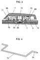
- Fig. 1 is a lateral cross section of a pushbutton switch in accordance with the first exemplary embodiment of the present invention
- Fig. 2 shows a perspective exploded view of the pushbutton switch shown in Fig. 1.
- switch member 2 is disposed on metallic substrate 1, and fixture 12 is mounted to an upper face of switch member 2.
- Switch member 2 comprises two films bonded each other and a switch contact 20 in between.
- An elastic body is, for example, rubber dome 3, and has depending protrusion 30 at upper inside thereof. Protrusion 30 is used for depressing switch contact 20.
- Rubber dome 3 is placed on switch member 2 though round hole 69 formed in resin-molded fixture 12 so that protrusion 30 can be located above switch contact 20.
- Longer key-top e.g. a space bar
- Stem 61 urges donut-shaped outer wall 35, viewed from top, near to the top of rubber dome 3, and is moved upwardly by elasticity of rubber dome 3.
- Two sets of link members 5 made of molded-resin are disposed at both sides of rubber dome 3 so that the two sets sandwich dome 3.
- one set of link members 5 comprises two link members 5 crossing each other at their center and fixed at the crossing point.
- link members 5 Four upper ends 50 of link members 5 are engaged rotatably with respective stoppers 63 disposed on the lower face of key-top 11, and four lower ends 55 of link members 5 are engaged rotatably and slidably with respective recesses 66 provided on fixture 12. These engagements are symmetrically constructed with regard to rubber dome 3 under key-top 11.
- fixture 12 is provided with quadrangle holes 70 in order to prevent stopper 65 provided underneath key-top 11 from hitting fixture 12.
- Stabilizing member 13 is detailed hereinafter. It is formed by squaring a hard metallic wire.
- the quadrangle formed by the metallic wire has a first side 71 and a second side.
- the second side is opened at its center and thus two terminals 72 are formed. Since key-top 11 has longer sides than other regular key-tops, first side 71 and the second side of the stabilizing member 13 are desirably longer than other two sides.
- Sections near to both of the ends of first side 71 are engaged rotatably with respective stoppers 65 provided on the lower face of key-top 11.
- Both terminals 72 of the second side are held rotatably and slidably by being extended through respective holes 68 punched in protrusions 67 formed on an upper face of fixture 12.
- Hole 68 shapes as an oval, and its longer diameter, slightly longer than the other one, crosses the longitudinal direction of key-top 11 at right angles.
- Hole 68 is located at an approximate center of a travelling range of first side 71 responsive to depressing key-top 11.
- stabilizing member 13 restrains not only vertical looseness at both sides of key-top 11 but also horizontal looseness.
- This embodiment can thus restrains looseness in both vertical and horizontal directions, and also save the conventional bosses depending from the key-top as well as guide holes on the fixture. As a result, a predetermined stroke can be provided in a low profile pushbutton switch. When these pushbutton switches are employed in an input device, the input device can be thinner and have a deep enough stroke with little looseness.
- stabilizing member 13 is described as a quadrangle where both of the terminals of the open side are bent inside.
- another form as shown in Fig. 4 can produce the same effect, i.e. first side 73 measures slightly shorter and both terminals 74 of a second side are bent outside.
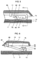
- Fig. 5 is a front cross section showing a right end of a pushbutton switch in accordance with the second exemplary embodiment of the present invention
- Fig. 6 is a lateral cross section taken on lines E-E of Fig. 5.
- the switch section including the rubber dome is omitted in Fig. 6.
- Fig. 7 is a perspective exploded view of an essential part of the same pushbutton switch shown in Fig. 5.
- the pushbutton switch in accordance with the second exemplary embodiment differs only in an engagement structure between fixture 14 and stabilizing member 15 from that of the first exemplary embodiment, and the others remain the same.
- First side 81 of stabilizing member 15 is engaged rotatably with two stoppers 65 provided on a lower face of key-top 11 at the sections near to both ends of side 81.
- Both terminals 82 of second side i.e. opened side of stabilizing member 15, are cranked and form approximate right angles with regard to a quadrangle face as shown in Fig. 7.
- Both terminals 82 are held rotatably and slidably in U-shaped grooves 76 formed on respective upper ends of two protrusions 75 provided on fixture 14.
- regular sections 83 of the second side are fit slidably into hook-shaped guide sections 77 provided on fixture 14, so that sections 83 hardly move upwardly.
- U-shaped groove 76 formed on the upper end of protrusion 75 is described here.
- Groove 76 is provided at the height so that the centers of both terminals 82 are located at an approximate center of a travelling range of side 81 responsive to depressing key-top 11. Further, the depth of groove 76 is greater than the center of terminal 82 but not greater than outer diameter of terminal 82.
- the height of protrusion 75 is thus limited to a lower height than that of exemplary embodiment 1.
- Depressing key-top 11 entails side 81 engaged with stopper 65 to travel downwardly by rotating. Both terminals 82 situated in grooves 76 slightly move to the right in Fig. 6, then return to the left. Regular sections 83 held by guide sections 77 of fixture 14 slightly move to the right in Fig. 6. Key-top 11 thus lowers smoothly, thereby activating the pushbutton switch.
- stabilizing member 15 shown in Fig. 5 another stabilizing member 16, having a crank shape on both of the terminals as shown in Fig. 8, can be employed.
- stabilizing member 16 downwardly bent section 86, extended from section 85 situated in groove 76, is urged to the upper face of fixture 14. Section 87 opposite to bent section 86 is engaged with hook-shaped guide section 77.
- This construction can eliminate a gap between section 87 and the lower face of guide section 77 thanks to the elasticity of bent section 86 to the upper face of fixture 14. As a result, operation noises due to subtle looseness can be restrained.
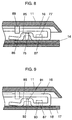
- Fig. 9 is a front cross section showing a right end of a pushbutton switch in accordance with the third exemplary embodiment of the present invention.
- This pushbutton switch can advantageously save the fixture from that of the second exemplary embodiment.
- metallic substrate 17 is punched and bent to form unitarily protrusions 92, guide sections 93 and stoppers (not shown) for engaging a lower end of a link member. These elements protrude upwardly through holes (not shown) punched on switch member 18 disposed on an upper face of substrate 17.
- U-shaped groove 91 is formed on the upper end of protrusion 92. Groove 91 holds a second side, i.e. crank-shaped terminal 85, and guide section 93 engages section 87 of stabilizing member 16.
- fixture 14, shown in Fig. 8 and used in the second exemplary embodiment can be saved, so that the material cost and assembly cost can be reduced, and further, the space below key-top 11 can be further widened. As a result, a further lower profile pushbutton switch can be realized.
- this third exemplary embodiment is described by comparing with the second exemplary embodiment; however, this advantage can be also applicable to the first exemplary embodiment.
- the lower profile pushbutton switch can be realized, where the looseness of the key-top is restrained, and a predetermined stroke is prepared, through the following advantageous structure.
Landscapes
- Push-Button Switches (AREA)
Applications Claiming Priority (2)
| Application Number | Priority Date | Filing Date | Title |
|---|---|---|---|
| JP17105998 | 1998-06-18 | ||
| JP17105998A JP3968873B2 (ja) | 1998-06-18 | 1998-06-18 | 押釦スイッチおよびこれを用いた入力装置 |
Publications (3)
| Publication Number | Publication Date |
|---|---|
| EP0966009A2 true EP0966009A2 (fr) | 1999-12-22 |
| EP0966009A3 EP0966009A3 (fr) | 2001-03-21 |
| EP0966009B1 EP0966009B1 (fr) | 2006-08-09 |
Family
ID=15916313
Family Applications (1)
| Application Number | Title | Priority Date | Filing Date |
|---|---|---|---|
| EP99111198A Expired - Lifetime EP0966009B1 (fr) | 1998-06-18 | 1999-06-09 | Interrupteur à bouton poussoir et dispositif d'entrée utilisant l'interrupteur |
Country Status (5)
| Country | Link |
|---|---|
| US (1) | US6100482A (fr) |
| EP (1) | EP0966009B1 (fr) |
| JP (1) | JP3968873B2 (fr) |
| CN (1) | CN1208796C (fr) |
| DE (1) | DE69932672D1 (fr) |
Cited By (5)
| Publication number | Priority date | Publication date | Assignee | Title |
|---|---|---|---|---|
| EP1139360A3 (fr) * | 2000-03-30 | 2003-05-14 | Mitsumi Electric Co., Ltd. | Dispositif commutateur à touche |
| EP1533819A1 (fr) * | 2003-11-20 | 2005-05-25 | Alps Electric Co., Ltd. | Dispositif commutateur à poussoir |
| EP2509087A1 (fr) * | 2011-04-06 | 2012-10-10 | Abb Ag | Support de bascule doté d'au moins un interrupteur à bascule d'une station de porte ou d'une station d'habitation d'un système de communication interne |
| CN104750184A (zh) * | 2013-12-26 | 2015-07-01 | 联想(新加坡)私人有限公司 | 用于降低输入设备噪声的系统和方法 |
| RU207420U1 (ru) * | 2021-02-19 | 2021-10-28 | Общество с ограниченной ответственностью "ИЭК ХОЛДИНГ" | Самовозвратный клавишный выключатель |
Families Citing this family (39)
| Publication number | Priority date | Publication date | Assignee | Title |
|---|---|---|---|---|
| DE19940051C1 (de) * | 1999-08-24 | 2000-11-16 | Siemens Pc Systeme Gmbh & Co K | Tastaturgehäuse für ein Tastenfeld einer Drucktasten-Tastatur |
| US6252184B1 (en) * | 2000-05-25 | 2001-06-26 | Chicony Electronics Co., Ltd. | Droplet proof keyboard for notebook computer |
| US6495782B1 (en) * | 2000-09-01 | 2002-12-17 | Silitek Corporation | Keycap having a balance lever for keyswitch structure |
| JP4533559B2 (ja) | 2001-06-07 | 2010-09-01 | 富士通株式会社 | キースイッチ及びキーボード |
| JP2003197058A (ja) * | 2001-12-27 | 2003-07-11 | Alps Electric Co Ltd | キースイッチ装置及びキーボード装置 |
| JP3941041B2 (ja) * | 2002-03-25 | 2007-07-04 | ミネベア株式会社 | キースイッチのスタビライザー機構 |
| KR100487212B1 (ko) * | 2002-05-15 | 2005-05-03 | 한국에스엠케이 주식회사 | 키스위치 |
| JP2004071406A (ja) * | 2002-08-07 | 2004-03-04 | Alps Electric Co Ltd | キースイッチ |
| JP2004079322A (ja) * | 2002-08-16 | 2004-03-11 | Fujitsu Ltd | キーボード及びそれを有する電子機器 |
| US6815627B2 (en) * | 2002-10-17 | 2004-11-09 | Lite-On Technology Corporation | Keyswitch structure for computer keyboard |
| JP2004273330A (ja) * | 2003-03-10 | 2004-09-30 | Mitsumi Electric Co Ltd | キーボード装置 |
| US6730868B1 (en) * | 2003-03-24 | 2004-05-04 | Alps Electric Co., Ltd. | Keyswitch device and keyboard device |
| JP4373273B2 (ja) * | 2004-05-17 | 2009-11-25 | アルプス電気株式会社 | キースイッチ及びこれを用いたキーボード入力装置 |
| KR100746009B1 (ko) * | 2005-10-26 | 2007-08-06 | 삼성전자주식회사 | 3차원 그래픽 유저 인터페이스를 위한 네비게이션 장치 |
| TW200725373A (en) * | 2005-12-30 | 2007-07-01 | Darfon Electronics Corp | Key structure |
| TW200727318A (en) * | 2006-01-03 | 2007-07-16 | Wistron Corp | Key and input device containing the key |
| CN100530469C (zh) * | 2006-01-09 | 2009-08-19 | 纬创资通股份有限公司 | 按键及包含该按键的输入装置 |
| JP2007227024A (ja) * | 2006-02-21 | 2007-09-06 | Mitsumi Electric Co Ltd | キースイッチ装置 |
| TWM314378U (en) * | 2006-11-27 | 2007-06-21 | Behavior Tech Computer Corp | Switch for computer keyboard |
| US20100231518A1 (en) * | 2008-04-29 | 2010-09-16 | Stephen Chen | Keyboard having multi-axis balance touch keys |
| US9208971B2 (en) * | 2009-03-04 | 2015-12-08 | Hewlett-Packard Development Company, L.P. | Keyboard insert |
| TWM362456U (en) * | 2009-04-02 | 2009-08-01 | Darfon Electronics Corp | Keyswitch and keyboard |
| US20110102323A1 (en) * | 2009-11-04 | 2011-05-05 | Tonny Chen | Keyboard having multi-axis balance touch keys |
| US9024214B2 (en) * | 2010-06-11 | 2015-05-05 | Apple Inc. | Narrow key switch |
| CN102403146B (zh) * | 2010-09-10 | 2014-03-26 | 富泰华工业(深圳)有限公司 | 按键结构及具有该按键结构的电子装置 |
| CN102403145B (zh) * | 2010-09-10 | 2015-02-04 | 富泰华工业(深圳)有限公司 | 按键结构及具有该按键结构的电子装置 |
| CN102403148B (zh) * | 2010-09-10 | 2014-03-26 | 富泰华工业(深圳)有限公司 | 按键结构及具有该按键结构的电子装置 |
| TWM416131U (en) * | 2011-03-30 | 2011-11-11 | Wistron Corp | Press button and portable electronic device |
| CN102891028B (zh) * | 2011-07-22 | 2015-09-02 | 赛恩倍吉科技顾问(深圳)有限公司 | 按键结构及具有该按键结构的电子装置 |
| FR2989182B1 (fr) | 2012-04-05 | 2015-06-26 | Coactive Technologies Llc | Dispositif de commande comportant un panneau superieur mobile d'actionnement d'un interrupteur de commutation |
| CN103383899A (zh) * | 2012-05-03 | 2013-11-06 | 尼得科电机有限公司 | 具有均匀触觉的防水开关 |
| FR3011948B1 (fr) | 2013-10-11 | 2017-03-03 | C&K Components S A S | Procede de reglage initial d'un dispositif de commande d'un appareil electronique |
| TWI601173B (zh) * | 2016-02-19 | 2017-10-01 | 致伸科技股份有限公司 | 按鍵結構 |
| CN106601510B (zh) * | 2017-01-24 | 2020-09-11 | 江苏传艺科技股份有限公司 | 用于键盘长按键的平衡结构 |
| TW201919079A (zh) * | 2017-11-03 | 2019-05-16 | 致伸科技股份有限公司 | 鍵盤 |
| TWI696095B (zh) * | 2018-08-07 | 2020-06-11 | 群光電子股份有限公司 | 鍵盤裝置 |
| CN110828218B (zh) * | 2018-08-10 | 2021-09-14 | 群光电子(苏州)有限公司 | 键盘装置 |
| US11869730B2 (en) | 2021-09-15 | 2024-01-09 | Darfon Electronics Corp. | Keycap support mechanism and keyswitch structure |
| US12002635B2 (en) | 2022-01-27 | 2024-06-04 | Darfon Electronics Corp. | Keyswitch structure |
Family Cites Families (12)
| Publication number | Priority date | Publication date | Assignee | Title |
|---|---|---|---|---|
| FR2063270A5 (fr) * | 1969-09-09 | 1971-07-09 | Sperac | |
| US4468145A (en) * | 1982-03-18 | 1984-08-28 | Oak Industries, Inc. | Keyboard space bar stabilizer |
| US4453063A (en) * | 1983-08-03 | 1984-06-05 | Illinois Tool Works Inc. | Keyswitch configuration with torque rod holder |
| US4771146A (en) * | 1985-08-19 | 1988-09-13 | Alps Electric Co., Ltd. | Keyboard key top mounting structure |
| US4918270A (en) * | 1989-03-06 | 1990-04-17 | Illinois Tool Works, Inc. | Appliance switch |
| US5117076A (en) * | 1989-09-22 | 1992-05-26 | Key Tronic Corporation | Quieting device for keytop leveling mechanisms |
| DE4022917A1 (de) * | 1990-07-19 | 1992-01-23 | Triumph Adler Ag | Tastatur fuer eine schreibmaschine o. dgl. |
| US5367135A (en) * | 1993-10-26 | 1994-11-22 | Chrysler Corporation | Push button construction for player control |
| US5668358A (en) * | 1994-07-05 | 1997-09-16 | Ultimate Rechnology Corporation | Reconfigurable keyboard |
| JP3540377B2 (ja) * | 1994-08-03 | 2004-07-07 | ミネベア株式会社 | 押ボタンスイッチ |
| US5941373A (en) * | 1997-05-30 | 1999-08-24 | Mustke Corporation | Integrated keyboard key assembly |
| TW346213U (en) * | 1997-08-01 | 1998-11-21 | Acer Peripherals Inc | Improvement for multiple pushing key |
-
1998
- 1998-06-18 JP JP17105998A patent/JP3968873B2/ja not_active Expired - Fee Related
-
1999
- 1999-06-09 DE DE69932672T patent/DE69932672D1/de not_active Expired - Lifetime
- 1999-06-09 EP EP99111198A patent/EP0966009B1/fr not_active Expired - Lifetime
- 1999-06-17 US US09/335,188 patent/US6100482A/en not_active Expired - Fee Related
- 1999-06-18 CN CNB991086805A patent/CN1208796C/zh not_active Expired - Fee Related
Cited By (8)
| Publication number | Priority date | Publication date | Assignee | Title |
|---|---|---|---|---|
| EP1139360A3 (fr) * | 2000-03-30 | 2003-05-14 | Mitsumi Electric Co., Ltd. | Dispositif commutateur à touche |
| KR100721912B1 (ko) * | 2000-03-30 | 2007-05-28 | 미츠미 덴끼 가부시키가이샤 | 키 스위치 장치 |
| EP1533819A1 (fr) * | 2003-11-20 | 2005-05-25 | Alps Electric Co., Ltd. | Dispositif commutateur à poussoir |
| EP2509087A1 (fr) * | 2011-04-06 | 2012-10-10 | Abb Ag | Support de bascule doté d'au moins un interrupteur à bascule d'une station de porte ou d'une station d'habitation d'un système de communication interne |
| RU2583152C2 (ru) * | 2011-04-06 | 2016-05-10 | Абб Аг | Держатель перекидной кнопки с по меньшей мере одной управляющей перекидной кнопкой дверной станции или квартирной станции домашней системы связи |
| CN104750184A (zh) * | 2013-12-26 | 2015-07-01 | 联想(新加坡)私人有限公司 | 用于降低输入设备噪声的系统和方法 |
| CN104750184B (zh) * | 2013-12-26 | 2018-07-31 | 联想(新加坡)私人有限公司 | 用于降低输入设备噪声的系统和方法 |
| RU207420U1 (ru) * | 2021-02-19 | 2021-10-28 | Общество с ограниченной ответственностью "ИЭК ХОЛДИНГ" | Самовозвратный клавишный выключатель |
Also Published As
| Publication number | Publication date |
|---|---|
| US6100482A (en) | 2000-08-08 |
| EP0966009A3 (fr) | 2001-03-21 |
| DE69932672D1 (de) | 2006-09-21 |
| JP3968873B2 (ja) | 2007-08-29 |
| JP2000011797A (ja) | 2000-01-14 |
| EP0966009B1 (fr) | 2006-08-09 |
| CN1208796C (zh) | 2005-06-29 |
| CN1240301A (zh) | 2000-01-05 |
Similar Documents
| Publication | Publication Date | Title |
|---|---|---|
| EP0966009B1 (fr) | Interrupteur à bouton poussoir et dispositif d'entrée utilisant l'interrupteur | |
| JP2861684B2 (ja) | キースイッチ装置 | |
| US5562203A (en) | Keyswitch | |
| US6956179B2 (en) | Rocker/pushbutton switch | |
| KR100298920B1 (ko) | 키보드장치 | |
| US6150624A (en) | Keyswitch device | |
| WO2018139077A1 (fr) | Interrupteur à bouton-poussoir | |
| EP1037226B1 (fr) | Interrupteur à bouton poussoir | |
| US6689967B2 (en) | Slide switch | |
| KR100348940B1 (ko) | 복수개의 수동 스위치를 구비하는 다방향 스위치 | |
| US4004121A (en) | Electrical switch with wire beam spring contact closer | |
| JP3147081B2 (ja) | キースイッチ装置、および、そのキースイッチ装置が使用されるキーボード装置 | |
| JP3203775B2 (ja) | キースイッチ装置 | |
| JP2607630Y2 (ja) | キースイッチ | |
| JP3352680B2 (ja) | キースイッチ装置 | |
| JP2000260259A (ja) | プッシュスイッチ | |
| JP2962357B2 (ja) | キースイッチ装置 | |
| JP3318320B2 (ja) | キースイッチ装置 | |
| JP3352678B2 (ja) | キースイッチ装置 | |
| JP3280358B2 (ja) | キースイッチ | |
| JP3316205B2 (ja) | キースイッチ装置 | |
| JP3352677B2 (ja) | キースイッチ装置 | |
| JP3318284B2 (ja) | キースイッチ装置 | |
| JP2004139994A (ja) | キースイッチ装置 | |
| JP3392845B2 (ja) | キースイッチ装置 |
Legal Events
| Date | Code | Title | Description |
|---|---|---|---|
| PUAI | Public reference made under article 153(3) epc to a published international application that has entered the european phase |
Free format text: ORIGINAL CODE: 0009012 |
|
| AK | Designated contracting states |
Kind code of ref document: A2 Designated state(s): DE FR GB |
|
| AX | Request for extension of the european patent |
Free format text: AL;LT;LV;MK;RO;SI |
|
| PUAL | Search report despatched |
Free format text: ORIGINAL CODE: 0009013 |
|
| AK | Designated contracting states |
Kind code of ref document: A3 Designated state(s): AT BE CH CY DE DK ES FI FR GB GR IE IT LI LU MC NL PT SE |
|
| AX | Request for extension of the european patent |
Free format text: AL;LT;LV;MK;RO;SI |
|
| 17P | Request for examination filed |
Effective date: 20010705 |
|
| AKX | Designation fees paid |
Free format text: DE FR GB |
|
| GRAP | Despatch of communication of intention to grant a patent |
Free format text: ORIGINAL CODE: EPIDOSNIGR1 |
|
| RIN1 | Information on inventor provided before grant (corrected) |
Inventor name: INOUE, TAKEFUMI Inventor name: AIMI, MITSUO Inventor name: KOMA, TETSUYA |
|
| GRAS | Grant fee paid |
Free format text: ORIGINAL CODE: EPIDOSNIGR3 |
|
| GRAA | (expected) grant |
Free format text: ORIGINAL CODE: 0009210 |
|
| AK | Designated contracting states |
Kind code of ref document: B1 Designated state(s): DE FR GB |
|
| REG | Reference to a national code |
Ref country code: GB Ref legal event code: FG4D |
|
| REF | Corresponds to: |
Ref document number: 69932672 Country of ref document: DE Date of ref document: 20060921 Kind code of ref document: P |
|
| PG25 | Lapsed in a contracting state [announced via postgrant information from national office to epo] |
Ref country code: DE Free format text: LAPSE BECAUSE OF FAILURE TO SUBMIT A TRANSLATION OF THE DESCRIPTION OR TO PAY THE FEE WITHIN THE PRESCRIBED TIME-LIMIT Effective date: 20061110 |
|
| EN | Fr: translation not filed | ||
| PLBE | No opposition filed within time limit |
Free format text: ORIGINAL CODE: 0009261 |
|
| STAA | Information on the status of an ep patent application or granted ep patent |
Free format text: STATUS: NO OPPOSITION FILED WITHIN TIME LIMIT |
|
| 26N | No opposition filed |
Effective date: 20070510 |
|
| PG25 | Lapsed in a contracting state [announced via postgrant information from national office to epo] |
Ref country code: FR Free format text: LAPSE BECAUSE OF FAILURE TO SUBMIT A TRANSLATION OF THE DESCRIPTION OR TO PAY THE FEE WITHIN THE PRESCRIBED TIME-LIMIT Effective date: 20070511 |
|
| PG25 | Lapsed in a contracting state [announced via postgrant information from national office to epo] |
Ref country code: FR Free format text: LAPSE BECAUSE OF FAILURE TO SUBMIT A TRANSLATION OF THE DESCRIPTION OR TO PAY THE FEE WITHIN THE PRESCRIBED TIME-LIMIT Effective date: 20060809 |
|
| PGFP | Annual fee paid to national office [announced via postgrant information from national office to epo] |
Ref country code: GB Payment date: 20080611 Year of fee payment: 10 |
|
| GBPC | Gb: european patent ceased through non-payment of renewal fee |
Effective date: 20090609 |
|
| PG25 | Lapsed in a contracting state [announced via postgrant information from national office to epo] |
Ref country code: GB Free format text: LAPSE BECAUSE OF NON-PAYMENT OF DUE FEES Effective date: 20090609 |