EP0966065A2 - Fixation de boítier de connexion électrique - Google Patents
Fixation de boítier de connexion électrique Download PDFInfo
- Publication number
- EP0966065A2 EP0966065A2 EP99304568A EP99304568A EP0966065A2 EP 0966065 A2 EP0966065 A2 EP 0966065A2 EP 99304568 A EP99304568 A EP 99304568A EP 99304568 A EP99304568 A EP 99304568A EP 0966065 A2 EP0966065 A2 EP 0966065A2
- Authority
- EP
- European Patent Office
- Prior art keywords
- bolt
- housing recess
- protrusion
- connection box
- electrical connection
- Prior art date
- Legal status (The legal status is an assumption and is not a legal conclusion. Google has not performed a legal analysis and makes no representation as to the accuracy of the status listed.)
- Withdrawn
Links
Images


Classifications
-
- H—ELECTRICITY
- H01—ELECTRIC ELEMENTS
- H01R—ELECTRICALLY-CONDUCTIVE CONNECTIONS; STRUCTURAL ASSOCIATIONS OF A PLURALITY OF MUTUALLY-INSULATED ELECTRICAL CONNECTING ELEMENTS; COUPLING DEVICES; CURRENT COLLECTORS
- H01R9/00—Structural associations of a plurality of mutually-insulated electrical connecting elements, e.g. terminal strips or terminal blocks; Terminals or binding posts mounted upon a base or in a case; Bases therefor
- H01R9/16—Fastening of connecting parts to base or case; Insulating connecting parts from base or case
- H01R9/18—Fastening by means of screw or nut
Definitions
- the present invention relates to a mounting for an electrical connection box which is to be mounted in an automatic vehicle.
- An electrical connection box has been used for housing electric equipment components such as various electric equipment circuits and electronic components used for automobiles, as well as for connecting junctions for wiring parts of a wire harness of the like.
- an electrical connection box is fastened to a vehicle by use of tightening member such as bolts and nuts. Therefore, the electrical connection box is equipped with a mounting area provided for such fastening.
- a mounting area 52 is provided with a generally U-shaped bolt housing recess 53. That is, one end of the bolt housing recess 53 is open, thus making it easy to carry out mounting by slidably mounting from this opened area when inserting a bolt 54 into the bolt housing recess 53 which is provided on a vehicle frame 55.
- Fig. 8(a) taking as a normal connection position, a position onto which the bolt is inserted into the deepest area of the bolt housing recess 53, the bolt 54 and nut 56 are tightened in this normal connection position.
- the bolt housing recess 53 is open at one end, there has been the possibility that the mounting area 56 may be separated from the bolt 54 when the nut 56 is loosened due to vibration during operation of the vehicle.
- the bolt housing recess 53 is provided to have a generally U-shape, having a certain distance from the open end thereof to the normal tightening position. Therefore, when tightening the bolt 54 and nut 56 at the normal tightening position, there has often been such connection at a position (an abnormal tightening area position) as shown in Fig. 8(b) other than the normal tightening position as shown in Fig. 8(a) with the electrical connection box 51 being displaced by a tightening force of the nut 56. In addition, in case of tightening at the abnormal tightening position, there has been deformation and damage to the mounting area 52 due to an excessive tightening torque resulting from a position at which an abnormally high face pressure exists between the washer 57 and the mounting area 52.
- the present invention was made in view of the above circumstances, and the object of the present invention is to provide an electrical connection box capable of positively preventing such improper fastening.
- an electrical connection box having a mounting area is provided with a housing recess capable of receiving a tightening member from open end thereof, and the tightening member is fastened at its mounting area.
- the mounting area is provided with a fastening area controlling device to control the fastening position of the above-mentioned fastening members.
- the fastening position control device includes a protrusion provided at the open end of the bolt housing recess in the mounting area of the electrical connection box.
- a further aspect of the protrusion is configured to be higher than a protruding height of the fastening member upon insertion into the bolt housing recess in the electrical connection box.
- the protrusion has on its upper surface an inclined surface which is inclined downwardly toward the deeper area, or closed end, of the bolt housing recess in the electrical connection box.
- the fastening position control device includes a protrusion provided on at least one inner wall surface of the bolt housing recess in the electrical connection box.
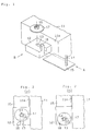
- Fig. 1 is a partial perspective view showing a portion of a first embodiment of the electrical connection box of the present invention.
- Figs. 2(a) and (b) are plan views showing a fastening mode of the first embodiment.
- Fig. 3 is a side view showing a fastening mode of the first embodiment as seen from the direction of the arrow A in Fig. 1.
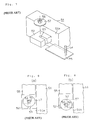
- Fig. 4 is a partial perspective view showing a second embodiment of the electrical connection box of the present invention.
- Fig. 5 is a front view showing a portion of a third embodiment of the electrical connection box of the present invention, as seen from the direction of the arrow B in Fig. 1.
- Fig. 6 is a partial plan view showing a portion of a fourth embodiment of the electrical connection box of the present invention.
- Fig. 7 is a partial perspective view showing a portion of a conventional electrical connection box.
- Figs. 8(a) and (b) are plan views showing a fastening mode of the conventional electrical connection box.
- a mounting area 12 formed of a synthetic resin is provided on a side wall 11a in an electrical connection box 11.
- a bolt housing recess 13 having a generally U-shape is provided on the mounting area 12. That is, one side of the bolt housing recess 13 has an open end, thus making it easy to carry out a mounting operation by slidably mounting from the open end when mounting the bolt housing recess 13 onto a bolt 14 which is provided on a vehicle frame 15.
- the bolt 14 inserted into the housing recess 13 is fastened with a nut 16 and a washer 17.
- a protrusion 18 is provided which extends upwardly.
- This protrusion 18 is, as shown in Fig. 2(a), formed at a position at which no interference is made with the washer 17 when the bolt 14 and nut 16 are mounted at the deepest area, or closed end, of the bolt housing recess 13.
- the height of the protrusion 18 is provided in such a manner that it is higher than the height of the bolt 14 when the bolt 14 is inserted into the bolt housing recess 13.
- the bolt 14 is provided on a vehicle frame 15 and is inserted into a bolt housing recess 13 as shown in Fig. 2(a). Then, by positioning the bolt 14 into the deepest area of the bolt housing recess 13 (corresponding to the normal fastening position as shown in the preceding Fig. 8(a)), the nut 16 is threaded onto the bolt 14 which protrudes from a mounting area 12 and through the washer 17, as jointly shown in Fig. 3. Therefore, the mounting area 12 and the vehicle frame 15 are fastened together by joining the bolt 14 and nut 16. Thus, the electrical connection box 11 is fastened to the vehicle.
- protrusion 18 is provided in such a manner that it is higher than the protruding height of the bolt 14 once inserted inside the bolt housing recess 13, in case of the above-mentioned improper fastening position, it becomes impossible to screw the nut 16 onto the bolt 14. Therefore, with fastening occurring between bolt 14 and nut 16 at the normal fastening position, any deformation and damage to the protrusion 18 can be avoided before hand.
- first embodiment of the present invention may be modified in the following manner. According to the first embodiment, only one protrusion 18 was provided at the open end of the bolt housing recess 13 of the mounting area 12. However, in a second embodiment illustrated in Fig. 4, two sets of protrusions 18 are provided at the open end of the bolt housing recess.
- an inclined surface 21 which inclines downwardly toward the closed end of the bolt housing recess 13 is provided on the tip of the protrusion 18.
- a protrusion 18 is provided on the open end of the bolt housing recess 13 in the mounting area 12 in order to control the fastening position between the bolt 14 and nut 16 in the preceding embodiments.
- a protrusion 22 is provided on both sides of the inner wall surface of the bolt housing recess 13 as shown in Fig. 6.
- the bolt 14 will be caught by the protrusions 22 when inserting the bolt 14 from the open end of the bolt housing recess 13.
- the bolt 14 will deflect the mounting area 12 in a direction by the arrow F shown in Fig. 6, and will move beyond the protrusions 22, and then into the normal fastening position of the bolt housing recess 13.
- a washer 17 is provided when the bolt 14 and nut 16 are fastened.
- washer 17 may be eliminated. In this way, the number of components can be reduced.
- the bolt 14 has been described as being provided on the vehicle frame 15 in the preceding embodiments, the bolt 14 may also be provided separately from the vehicle frame 15. In this way, the vehicle frame 15 and the mounting area 16 are jointly fastened with the bolt 14 and the nut 16.
- a fastening position of fastening members can be controlled by a fastening position control device thereby avoiding improper fastening.
- interference occurs between fastening members and a protrusion, so that it is difficult to have the fastening members fastened at the edge of the opening on the housing concave area. Therefore, the fastening position of fastening members can be controlled, thereby preventing improper fastening.
- fastening of the fastening members can be prevented at a position at which interference occurs with a protrusion, and possible deformation and damage can further be avoided in advance of the protrusion caused by fastening of the fastening members.
- movement of mounting area can be controlled for fastening members when fastening the fastening members, thereby preventing possible improper fastening.
Landscapes
- Connection Or Junction Boxes (AREA)
- Connections Arranged To Contact A Plurality Of Conductors (AREA)
Applications Claiming Priority (2)
| Application Number | Priority Date | Filing Date | Title |
|---|---|---|---|
| JP17340698A JP3334623B2 (ja) | 1998-06-19 | 1998-06-19 | 電気接続箱 |
| JP17340698 | 1998-06-19 |
Publications (2)
| Publication Number | Publication Date |
|---|---|
| EP0966065A2 true EP0966065A2 (fr) | 1999-12-22 |
| EP0966065A3 EP0966065A3 (fr) | 2001-06-20 |
Family
ID=15959845
Family Applications (1)
| Application Number | Title | Priority Date | Filing Date |
|---|---|---|---|
| EP99304568A Withdrawn EP0966065A3 (fr) | 1998-06-19 | 1999-06-11 | Fixation de boítier de connexion électrique |
Country Status (4)
| Country | Link |
|---|---|
| US (1) | US6159044A (fr) |
| EP (1) | EP0966065A3 (fr) |
| JP (1) | JP3334623B2 (fr) |
| CN (1) | CN1239842A (fr) |
Families Citing this family (5)
| Publication number | Priority date | Publication date | Assignee | Title |
|---|---|---|---|---|
| JP2005353465A (ja) * | 2004-06-11 | 2005-12-22 | Sumitomo Wiring Syst Ltd | 電気接続箱のヒュージブルリンク装着構造 |
| CN201018050Y (zh) * | 2006-12-22 | 2008-02-06 | 富士康(昆山)电脑接插件有限公司 | 电连接器 |
| CN102146953A (zh) * | 2010-02-09 | 2011-08-10 | 鸿富锦精密工业(深圳)有限公司 | 紧固件及使用紧固件的固定结构 |
| JP5798777B2 (ja) * | 2011-04-04 | 2015-10-21 | 矢崎総業株式会社 | ワッシャ保持用ブラケット構造 |
| JP7344843B2 (ja) * | 2020-06-15 | 2023-09-14 | 株式会社日立産機システム | モールド変圧器 |
Family Cites Families (10)
| Publication number | Priority date | Publication date | Assignee | Title |
|---|---|---|---|---|
| US3346286A (en) * | 1965-08-31 | 1967-10-10 | Burroughs Corp | Component mounting employing a threaded bolt driven at its threaded end |
| US4921433A (en) * | 1987-02-17 | 1990-05-01 | Cooper Power Systems, Inc. | Variable portable feedthru device |
| US4941769A (en) * | 1988-04-05 | 1990-07-17 | Yazaki Corporation | Structure for fastening a resin member with a threaded bolt |
| US5178557A (en) * | 1990-10-31 | 1993-01-12 | Japan Aviation Electronics Industry, Limited | Electric connector having symmetric locking blocks at opposite ends |
| US5125853A (en) * | 1991-05-21 | 1992-06-30 | Japan Aviation Electronics Industry, Limited | Electric connector |
| JP2582762Y2 (ja) * | 1993-03-09 | 1998-10-08 | 住友電装株式会社 | 分岐接続箱のケースロック構造 |
| JP2832132B2 (ja) * | 1993-06-11 | 1998-12-02 | 矢崎総業株式会社 | 樹脂成形品の取付ブラケット |
| JPH0739043A (ja) * | 1993-07-23 | 1995-02-07 | Sumitomo Wiring Syst Ltd | 電気接続箱のパッキン構造およびパッキン材の形成方法 |
| GB9400024D0 (en) * | 1994-01-04 | 1994-03-02 | Amp Gmbh | Centering spring support for panel mount connectors |
| US5622519A (en) * | 1995-04-28 | 1997-04-22 | Molex Incorporated | Retention system for electrical connectors on printed circuit boards |
-
1998
- 1998-06-19 JP JP17340698A patent/JP3334623B2/ja not_active Expired - Fee Related
-
1999
- 1999-06-11 EP EP99304568A patent/EP0966065A3/fr not_active Withdrawn
- 1999-06-14 CN CN99108438A patent/CN1239842A/zh active Pending
- 1999-06-15 US US09/332,989 patent/US6159044A/en not_active Expired - Lifetime
Also Published As
| Publication number | Publication date |
|---|---|
| US6159044A (en) | 2000-12-12 |
| JP2000013955A (ja) | 2000-01-14 |
| CN1239842A (zh) | 1999-12-29 |
| JP3334623B2 (ja) | 2002-10-15 |
| EP0966065A3 (fr) | 2001-06-20 |
Similar Documents
| Publication | Publication Date | Title |
|---|---|---|
| US6462270B1 (en) | Two-piece junction box cover having gutters for reducing water infiltration | |
| US5800208A (en) | Movable connector-mounting construction | |
| US7002076B2 (en) | Electric box extender | |
| US6053780A (en) | Fusible link mounting method and terminal and fusible link housing used in the same method | |
| EP0817345A1 (fr) | Boíte de connexion électrique | |
| US5066246A (en) | Mounting bracket for an electrical connector | |
| CA2755861A1 (fr) | Disjoncteurs dotes d'un moyen de retenue de vis de borne et procedes de fabrication associes | |
| US6159044A (en) | Mounting for an electrical connection box | |
| US20060243870A1 (en) | Mounting bracket structure | |
| JPH1037938A (ja) | ボルト脱落防止ホルダー | |
| US6077116A (en) | Fixing structure for electrical connection assembly | |
| JP3046742B2 (ja) | 電気接続箱の取付構造 | |
| JP3094144B2 (ja) | ロック構造及びロック解除用治具及びロック解除方法 | |
| JPH0676867A (ja) | アース用端子 | |
| JP2678020B2 (ja) | 圧縮機の電装品カバー固定装置 | |
| JP2973848B2 (ja) | 電装品箱の固定構造 | |
| JP3366215B2 (ja) | 端子固定部におけるナットの圧入構造 | |
| JP5024946B2 (ja) | 電気接続箱 | |
| JP2002171636A (ja) | 電気接続箱の取付構造 | |
| JP2715360B2 (ja) | 端 子 | |
| JP3827850B2 (ja) | 部品の取付け構造 | |
| JP3080917B2 (ja) | 動力伝達ケーブルの取付け端末構造 | |
| KR20250133060A (ko) | 도난 방지 브라켓 및 이를 포함하는 차량용 제어 장치 | |
| JP2516471Y2 (ja) | 電気接続箱 | |
| KR200410105Y1 (ko) | 정션박스의 오버토크 방지구조 |
Legal Events
| Date | Code | Title | Description |
|---|---|---|---|
| PUAI | Public reference made under article 153(3) epc to a published international application that has entered the european phase |
Free format text: ORIGINAL CODE: 0009012 |
|
| 17P | Request for examination filed |
Effective date: 19990706 |
|
| AK | Designated contracting states |
Kind code of ref document: A2 Designated state(s): AT BE CH CY DE DK ES FI FR GB GR IE IT LI LU MC NL PT SE |
|
| AX | Request for extension of the european patent |
Free format text: AL;LT;LV;MK;RO;SI |
|
| PUAL | Search report despatched |
Free format text: ORIGINAL CODE: 0009013 |
|
| AK | Designated contracting states |
Kind code of ref document: A3 Designated state(s): AT BE CH CY DE DK ES FI FR GB GR IE IT LI LU MC NL PT SE |
|
| AX | Request for extension of the european patent |
Free format text: AL;LT;LV;MK;RO;SI |
|
| RIC1 | Information provided on ipc code assigned before grant |
Free format text: 7H 01R 13/46 A, 7H 01R 9/18 B, 7H 01R 13/74 B |
|
| STAA | Information on the status of an ep patent application or granted ep patent |
Free format text: STATUS: THE APPLICATION HAS BEEN WITHDRAWN |
|
| 18W | Application withdrawn |
Withdrawal date: 20011215 |