EP0966135A2 - Kodierung für Mehrträgerübertragung - Google Patents
Kodierung für Mehrträgerübertragung Download PDFInfo
- Publication number
- EP0966135A2 EP0966135A2 EP99304421A EP99304421A EP0966135A2 EP 0966135 A2 EP0966135 A2 EP 0966135A2 EP 99304421 A EP99304421 A EP 99304421A EP 99304421 A EP99304421 A EP 99304421A EP 0966135 A2 EP0966135 A2 EP 0966135A2
- Authority
- EP
- European Patent Office
- Prior art keywords
- symbol
- dmt
- carrier signal
- value
- symbols
- Prior art date
- Legal status (The legal status is an assumption and is not a legal conclusion. Google has not performed a legal analysis and makes no representation as to the accuracy of the status listed.)
- Withdrawn
Links
- 230000005540 biological transmission Effects 0.000 title claims abstract description 35
- 238000000034 method Methods 0.000 claims description 22
- 238000004891 communication Methods 0.000 description 21
- 125000004122 cyclic group Chemical group 0.000 description 14
- 238000011144 upstream manufacturing Methods 0.000 description 13
- 230000006870 function Effects 0.000 description 12
- 230000011664 signaling Effects 0.000 description 10
- 230000004044 response Effects 0.000 description 9
- 230000003595 spectral effect Effects 0.000 description 8
- 239000000969 carrier Substances 0.000 description 7
- 238000012549 training Methods 0.000 description 6
- 238000012545 processing Methods 0.000 description 5
- 230000000694 effects Effects 0.000 description 4
- 230000036039 immunity Effects 0.000 description 4
- 239000004606 Fillers/Extenders Substances 0.000 description 3
- 230000000295 complement effect Effects 0.000 description 2
- 239000000284 extract Substances 0.000 description 2
- 238000000605 extraction Methods 0.000 description 2
- 230000006872 improvement Effects 0.000 description 2
- 230000008569 process Effects 0.000 description 2
- 238000011084 recovery Methods 0.000 description 2
- 238000013459 approach Methods 0.000 description 1
- 238000010420 art technique Methods 0.000 description 1
- 230000008901 benefit Effects 0.000 description 1
- 238000005516 engineering process Methods 0.000 description 1
- 230000002452 interceptive effect Effects 0.000 description 1
- 238000013507 mapping Methods 0.000 description 1
- 238000005070 sampling Methods 0.000 description 1
- 238000012360 testing method Methods 0.000 description 1
Images


Classifications
-
- H—ELECTRICITY
- H04—ELECTRIC COMMUNICATION TECHNIQUE
- H04L—TRANSMISSION OF DIGITAL INFORMATION, e.g. TELEGRAPHIC COMMUNICATION
- H04L27/00—Modulated-carrier systems
- H04L27/26—Systems using multi-frequency codes
- H04L27/2601—Multicarrier modulation systems
- H04L27/2602—Signal structure
-
- H—ELECTRICITY
- H04—ELECTRIC COMMUNICATION TECHNIQUE
- H04L—TRANSMISSION OF DIGITAL INFORMATION, e.g. TELEGRAPHIC COMMUNICATION
- H04L1/00—Arrangements for detecting or preventing errors in the information received
- H04L1/08—Arrangements for detecting or preventing errors in the information received by repeating transmission, e.g. Verdan system
-
- H—ELECTRICITY
- H04—ELECTRIC COMMUNICATION TECHNIQUE
- H04L—TRANSMISSION OF DIGITAL INFORMATION, e.g. TELEGRAPHIC COMMUNICATION
- H04L27/00—Modulated-carrier systems
- H04L27/26—Systems using multi-frequency codes
- H04L27/2601—Multicarrier modulation systems
- H04L27/2614—Peak power aspects
-
- H—ELECTRICITY
- H04—ELECTRIC COMMUNICATION TECHNIQUE
- H04L—TRANSMISSION OF DIGITAL INFORMATION, e.g. TELEGRAPHIC COMMUNICATION
- H04L27/00—Modulated-carrier systems
- H04L27/26—Systems using multi-frequency codes
- H04L27/2601—Multicarrier modulation systems
- H04L27/2614—Peak power aspects
- H04L27/2623—Reduction thereof by clipping
- H04L27/2624—Reduction thereof by clipping by soft clipping
Definitions
- This invention relates generally to communications and, more particularly, to high-speed data communications systems.
- Plain Old Telephone Service is typically deployed to individual subscribers over a twisted pair of wire.
- POTS Plain Old Telephone Service
- Asymmetric Digital Subscriber Loop ADSL
- One version of ADSL increases the bandwidth of the twisted pair up to 1.1 Mhz (megahertz), which provides transmission capabilities up to 9 Mbps (millions of bits per second).
- ADSL allocates different amounts of bandwidth between upstream communications and downstream communications (hence the term "asymmetric"), with upstream communications having less bandwidth than downstream communications.
- asymmetric bandwidth between upstream communications and downstream communications
- the upstream channel may have an allocated bandwidth from 25 Khz (kilohertz) to 138 Khz; while in the downstream direction, i.e., from the CO to the CPE, the downstream channel may have an allocated bandwidth from 138 Khz to 1.1 Mhz.
- the POTS voice channel (0 to 4 Khz) is unaffected by ADSL.).
- the upstream channel and downstream channel are disjoint and also adjacent.
- ADSL systems can be constructed where the upstream channel partially overlaps with the downstream channel. While this provides more bandwidth for the downstream signal, this also requires the use of echo cancellation techniques.
- modulation methods carrierless amplitude phase (CAP) modulation or Discrete Multi-Tone (DMT) modulation can be used.
- CAP carrierless amplitude phase
- DMT Discrete Multi-Tone
- DMT is a form of orthogonal frequency division multiplexing (OFDM).
- DMT modulation utilizes multiple carriers (also sometimes referred to as subcarriers) for conveying information.
- the allocated frequency range is divided into K carrier channels, K > 1 , each carrier channel separated by approximately 4 Khz.
- a DMT-based ADSL system transmits what is referred to as "multi-tone symbols" or "DMT symbols.”
- a DMT-based ADSL system is particularly susceptible to impulse noise (which, in the frequency domain goes across all frequencies).
- impulse noise hits can cause unrecoverable errors in a DMT-based ADSL system.
- the high-speed of these ADSL systems presents challenges in terms of providing equipment designs that not only provide protection against impulse noise but are also comparably lower in cost, i.e., have less processor complexity.
- a multi-carrier transmission signal is formed where each symbol value is transmitted in a redundant form over a plurality of consecutive symbol intervals.
- an encoder operates on a DMT input signal representing f symbols/sec. to generate, for transmission, a DMT output signal representing Nf symbols/sec., where N > 1 .
- the redundant form is illustrated by repeating each input symbol value in N consecutive symbol intervals in the DMT output signal.
- an encoder operates on a DMT input signal representing f symbols/sec. to generate, for transmission, a DMT output signal representing Nf symbols/sec., where N > 1 .
- every N DMT input symbol values are transmitted in 2N consecutive symbol intervals in the DMT output signal.
- These 2N consecutive symbol intervals in the DMT output signal include 1) N symbols whose values equal the respective N DMT input symbol values and 2) N symbols whose values are a function of the respective N DMT input symbol values.
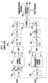
- ADSL communications equipment 100 shown in FIG. 1, is described in order to provide some background information.
- the elements shown in FIG. 1 are well-known and will not be described in detail.
- ADSL equipment 100 is located at the CO.
- the corresponding ADSL equipment located at the subscriber's premise i.e., the far-end ADSL equipment, or CPE, is similar and will not be described herein.
- ADSL equipment 100 conforms to ANSI T1.413.
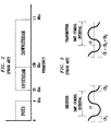
- the ADSL system represented by FIG. 1 allocates bandwidth as shown in FIG. 2.
- the POTS channel is in the 0 to 4 Khz range
- the upstream channel i.e., from the CPE to the CO
- the downstream channel from the CO to the CPE
- the upstream channel and downstream channel are disjoint and also adjacent.
- the transmitter portion of ADSL equipment 100 comprises serial-to-parallel convener (S/P) 105, symbol mappers 110, inverse fast Fourier transform element (IFFT) 115, cyclic extender (CE) 120, parallel-to-serial converter (P/S) 125, digital-to-analog converter (D/A) 130, and hybrid 135.
- a data signal is applied to S/P 105, which converts the data signal from serial to parallel form and provides 256 signals n 0 through n 255 .
- Signals n 0 through n 255 are applied to symbol mappers 110.
- the latter comprises 256 symbol mappers, one for each of the parallel output signals of S/P 105.
- the number of bits encoded by each symbol mapper, and hence the number of bits S/P 125 provides in each n i is determined as a result of a spectral response determined during a training phase.
- the resulting 256 output symbol streams from symbol mappers 110 are complex valued and are applied to IFFT 115, which modulates the various different carriers with the output symbol stream to provide 512 output signals.
- IFFT 115 takes the complex conjugate (not shown) of the 256 output symbol streams to provide 512 real signals.
- the 512 output signals from IFFT 115 are applied to CE 120, which performs cyclic extension (described below) and provides extended symbols in parallel form.
- ISI intersymbol interference
- cyclic extension a DMT symbol is partially, and cyclically, extended in both directions.
- FIG. 3 A conceptual illustration is shown in FIG. 3 for a single carrier at a receiver.
- the DMT symbol is represented by, e.g., the phase of carrier 10.
- Cyclic extension occurs before and after the DMT symbol.
- carrier 10 is allowed to extend in both directions as represented by cyclic extension 1 ( CE 1 ) and cyclic extension 2 ( CE 2 ), which may or may not be equal to each other.
- the term extended DMT symbol includes the DMT symbol plus at least one cyclic extension. The value of CE is adjusted as a function of the span of an estimated channel impulse response (described below).
- P/S 125 provides a serial output signal, the DMT symbol plus cyclic extender, that is converted from digital to analog by A/D 130.
- the latter provides a downstream ADSL signal representing a sequence of extended DMT symbols, to hybrid 135, which couples this downstream ADSL signal to combiner/splitter 150, which adds in the POTS channel.
- the output signal from combiner/splitter 150 comprises the POTS channel in the 0 to 4 Khz range and the downstream signal in the 138 Khz to 1.1 Mhz range and is applied to the communications channel, represented by twisted pair 151.
- the receiver portion of ADSL equipment 100 comprises hybrid 135, analog-to-digital converter (A/D) 155, CE gate 160, S/P 165, fast Fourier transform element 170, equalizer/symbol slicer 175, and P/S 180.
- Combiner/splitter 150 splits out the POTS channel from the signal present on twisted pair 151 and provides the remaining upstream ADSL signal (in the 138 Khz to 1.1 Mhz range) to hybrid 135. The latter couples the upstream ADSL signal to A/D 155, which converts the signal from analog to digital for application to CE gate 160.
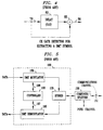
- CE gate 160 extracts DMT symbols from each received extended DMT symbol, as known in the art. (It should be noted that the function of CE gate 160 could alternatively be performed after S/P 165.)
- CE gate 150 determines when to begin the extraction process.
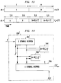
- An illustrative structure for use within CE gate 150 is shown in FIG. 4.
- a signal 79, representing extended DMT symbols, is applied to delay element 80 and combiner 85.
- Delay element 80 in combination with combiner 85 allows comparison of a current sample with the value of the sample that occurred 512 points earlier.
- Combiner 85 provides a signal indicative of when in the extended DMT symbol the extraction process can being, i.e., what possible 512 samples represent the DMT symbol.
- Equalizers/symbol slicers 175 represents a plurality of equalizer and symbol slicer structures, one for each carrier for recovering the data signal in parallel form.
- the output signals of equalizers/symbol slicers 175 are applied to P/S 180 for converting the data signal back into serial form.
- ADSL equipment 100 is shown in FIG. 5 as comprising DMT modulator 185, DMT demodulator 195, hybrid 135, and controller 190.
- DMT modulator 185 operates as described above with respect to transmission of an ADSL signal and includes the above-mentioned components of FIG. 1 such as S/P 105, etc.
- DMT demodulator 195 operates as described above with respect to reception of an ADSL signal and includes the above-mentioned components of FIG. 1 such as A/D 155, etc.
- controller 190 which is illustratively a stored-program controller and associated memory as known in the art. Controller 190 controls and receives information from DMT modulator 185 and DMT demodulator 195, via signaling 196 and 197, respectively.
- an ADSL communications session comprises a training phase and a communications phase.
- ADSL equipment 100 exchanges signaling with the far-end ADSL equipment (not shown).
- Controller 190 uses this signaling to establish the above-mentioned spectral response of communications channel 151 (as does a similar controller in the far-end ADSL equipment). The spectral response is affected by such items as cross-talk, physical loop length of the twisted pair of communications channel 151, etc.
- controller 190 To determine the spectral response of the twisted pair, controller 190 generally performs the following steps. First, DMT modulator 185 transmits a wide band test signal to the far-end ADSL equipment. Upon receipt, the far-end ADSL equipment evaluates the received signal to determine the spectral response of the twisted pair. Once the spectral response is determined, the far-end ADSL equipment generates a bit loading table and sends the bit loading table to ADSL equipment 100.
- the bit loading table includes, for each carrier, a number of bits that each carrier can support. The bit loading table is used by controller 190 to select various operating parameters such as symbol mappings at each carrier.
- each carrier can support up to M bits of information, the actual amount of bits a carrier supports varies due to the spectral response of the twisted pair at the different carrier frequencies. For example, one carrier may be able to accommodate 12 bits while another may be only able to accommodate 2 bits.)
- a multi-carrier signal is more susceptible to impulse noise.
- the processing complexity of multi-carrier equipment increases with symbol rate because of the additional multi-carrier signal processing (e.g., IFFT in the transmitter portion and FFT in the receiver portion).
- additional multi-carrier signal processing e.g., IFFT in the transmitter portion and FFT in the receiver portion.
- IFFT IFFT in the transmitter portion
- FFT FFT in the receiver portion
- ADSL Lite One form of ADSL transmission is known as ADSL "Lite."
- ADSL Lite the transmission rate is around 1 Mbps (millions of bits per second) versus ADSL "Heavy” in which the transmission rate is around 6 Mbps.
- ADSL Lite only a subset of carriers, or tones, are used, e.g., 1 ⁇ 2. However, and as described further below, one can use the entire available set of carriers and repeat the same DMT symbol and still maintain the same effective data rate.
- inventive concept transmits symbols in a "redundant form.” As described further below, this redundant form can be achieved in any number of ways. As such, the inventive concept is not restricted to the redundant forms described herein. In addition, the inventive concept transmits redundant forms of "symbols.” For the purposes of this description the terms extended DMT symbol and DMT symbol are interchangeable. Whether the extended DMT symbol is provided in a redundant form or the DMT symbol is provided in redundant form is a mere choice of hardware implementation ⁇ the inventive concept still applies.
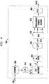
- FIG. 6 An illustrative ADSL system embodying the principles of the invention is shown in FIG. 6. As described further below, this ADSL system performs "Time Redundant Bandwidth Expansion.”
- the ADSL system comprises ADSL CO equipment 200 coupled to ADSL consumer premise (CP) equipment 300 via twisted pair 136. Each of these is also referred to herein as a multi-carrier endpoint. (The splitter/combiner for the POTS channel has been left out for simplicity.) It is assumed that the ADSL DMT system has disjoint and adjacent upstream and downstream channels (although this is not necessary to the inventive concept). For simplicity, only downstream transmission is described. Upstream transmission is similar and will not be described herein. It should be noted that, other than the inventive concept, the elements shown in FIGs. 6 - 8 are well-known and will not be described in detail. In addition, techniques for generating different clock frequencies are well-known and will not be described herein.
- Transmitter portion 250 comprises serial-to-parallel converter (S/P) 205, symbol mappers 210, inverse fast Fourier transform element (IFFT) 215, cyclic extender (CE) 220, parallel-to-serial converter (P/S) 225, digital-to-analog converter (D/A) 230, Nf coder 290, and hybrid 235.
- S/P 205 serial-to-parallel converter
- IFFT inverse fast Fourier transform element
- CE cyclic extender
- P/S parallel-to-serial converter
- D/A digital-to-analog converter
- hybrid 235 hybrid 235.
- a data signal is applied to S/P 205, which converts the data signal from serial to parallel form and provides 256 signals n 0 through n 255 .
- Signals n 0 through n 255 are applied to symbol mappers 210.
- the latter comprises 256 symbol mappers, one for each of the parallel output signals of S/P 205.
- the resulting 256 output symbol streams from symbol mappers 210 are complex valued and are applied to IFFT 215, which modulates the various different carriers with the output symbol stream to provide 512 output signals.
- IFFT 215 takes the complex conjugate (not shown) of the 256 output symbol streams to provide 512 real signals.
- the 512 output signals from IFFT 215 are applied to CE 220, which performs cyclic extension (described above) and provides extended symbols in parallel form.
- Nf coder 290 receives the applied DMT symbols at the rate f and forms a multi-carrier signal, Nf , for transmission having a symbol rate Nf , where the applied DMT symbols appear in a redundant form.
- the multi-carrier signal Nf is convened from digital to analog by A/D 230. The latter provides a downstream ADSL signal representing a sequence of extended DMT symbols at a symbol rate Nf to hybrid 135, which couples this downstream ADSL signal to twisted pair 136.
- Nf coder 290 comprises a one symbol buffer 291.
- the applied DMT symbols are sampled at a frequency f into buffer 291.
- the DMT sample value in buffer 291 is clocked out at a rate Nf.
- Receiver portion 350 comprises hybrid 335, analog-to-digital converter (A/D) 355, Nf decoder 395, CE gate 360, S/P 365, fast Fourier transform element 370, equalizer/symbol slicer 375, and P/S 380.
- Hybrid 335 couples the received downstream ADSL signal from twisted pair 136 to A/D 355, which converts the signal from analog to digital and provides a digital form of a received multi-carrier signal representing a sequence of received extended DMT symbols having a symbol rate Nf symbols/sec.
- Nf decoder 395 recovers extended DMT symbols (described below) and provides the recovered extended DMT symbols at f symbols/sec.
- CE gate 360 extracts DMT symbols from each received extended DMT symbol, as known in the art. (It should be noted that the function of CE gate 360 could alternatively be performed after S/P 365.)
- the output signal from CE gate 360 is applied to S/P 365, which provides 512 output signals to FFT 370 which recovers the symbols from each of the carriers.
- Equalizers/symbol slicers 375 represents a plurality of equalizer and symbol slicer structures, one for each carrier for recovering the data signal in parallel form.
- the output signals of equalizers/symbol slicers 375 are applied to P/S 380 for converting the data signal back into serial form.
- Nf coder 395 comprises N symbol buffer 396, and decision element 397.
- the received multi-carrier signal is sampled at Nf symbols/sec. into symbol buffer 396.
- the latter stores N sampled DMT symbol values.
- decision element 397 (described further below) which makes a decision as to the received DMT symbol.
- These recovered DMT symbols are provided to CE gate 360 at a symbol rate of f symbols/sec.(described above).
- the inventive concept of using redundant forms of the symbols does not add significant complexity and improves protection against impulse noise (described below). As shown in FIGs. 7 and 9 implementations of the inventive concept do not require additional IFFT processing in the transmitter, nor FFT processing in the receiver.
- N 2 .
- DMT symbol sequence 20 represents a portion of a stream of selected DMT symbols applied to Nf coder 290.
- Nf coder 290 receives a DMT symbol A followed by a DMT symbol B in the next symbol interval T .
- Nf coder 290 provides 2 corresponding output symbols, as represented by sequence 25, which shows transmission of 2 DMT A symbols at a rate 2/T followed by transmission of 2 DMT B symbols, etc.
- corresponding decision element 397 in decoder element 395, of FIG. 10 simply recovers the DMT symbol by adding the corresponding samples of the two received copies A' and A''. The results of the addition are applied to CE gate 360 (described above).
- DMT symbol sequence 30 represents a portion of a stream of selected DMT symbols applied to Nf coder 290.
- Nf coder 290 receives a DMT symbol A followed by a DMT symbol B in the next symbol interval T .
- Nf coder 290 provides 3 corresponding output symbols, as represented by sequence 35, which shows transmission of 3 DMT A symbols at a rate 3/T followed by transmission of 3 DMT B symbols, etc.
- sequence 35 3
- the bandwidth is used and a combining gain of 4.5 dB results in the presence of Gaussian noise. (It should be noted that all of this 4.5 dB combining gain may not be realized if the channel has a significant attenuation in the expanded portions of the frequency band).
- corresponding decision element 397 in decoder element 395, of FIG. 10 simply recovers the DMT symbol by adding the corresponding samples of the three received copies A' , A'' and A'''. The results of the addition are applied to CE gate 360 (described above).
- decision element 397 uses a majority rule decision algorithm for selecting the recovered symbol. In particular, decision element 397 selects those two received copies that match and discards the received copy that does not match. (This decision algorithm assumes that impulse noise will predominately effect only one symbol at a time. As such other algorithms may also be used.)
- DMT symbol sequence 40 represents a portion of a stream of selected DMT symbols applied to Nf coder 290.
- Nf coder 290 receives a DMT symbol A. This is followed by a DMT symbol B in the next symbol interval T .
- Nf coder 290 provides 4 corresponding output symbols as represented by sequence 45, which shows transmission of 4 DMT symbols at a rate 2/T .
- These output symbols include 1) 2 symbols whose values equal the respective 2 DMT input symbol values and 2) 2 symbols whose values are a function of the respective 2 DMT input symbol values.
- the illustrative functions are represented by ((A+B)/ ⁇ 2) and ((A-B) ⁇ 2) .
- Nf coder 290' A corresponding modified form of Nf coder 290 is shown in FIG. 14 as Nf coder 290'.
- the latter comprises 2 symbol buffer 291', which receives input DMT symbols at a rate f . These two symbol values are applied to 4 symbol buffer 294 and to elements 292 and 293, which generate the other required redundant forms of these symbol values.
- Nf 2
- corresponding decision element 397 (in decoder element 395, of FIG. 10) is modified to perform the complementary functions to recover copies A', A'' and A''' and B', B'' and B''', as illustrated in FIG. 15.
- Illustrative Nf decoder 395' comprises 2N symbol buffer 396', and decision element 397'.
- the received multi-carrier signal is sampled at Nf symbols/sec. into symbol buffer 396'.
- the latter stores 2N sampled DMT symbol values.
- These 2N sample values are applied to decision element 397' which makes a decision as to the received DMT symbol using the complementary functions shown above.
- decision element 397' also uses a majority rule decision algorithm for selecting the recovered symbol. In particular, decision element 397' selects those two received copies that match and discards the received copy that does not match. The selected symbol is applied CE gate 360 at a symbol rate of f symbols/sec.
- a signal modulated by the DMT scheme typically has a high peak-to-average signal ratio.
- a transmit DMT signal can be clipped by a certain probability. To reduce this probability, the prior art technique of "back-off' is used. Unfortunately, back-off increases the power consumption in analog drivers (not shown) and reduces the available bits in the A/D for a given average power in the corresponding received signal.
- DMT symbol sequence 20 represents a portion of a stream of selected DMT symbols applied to Nf coder 290. For example, in the first symbol interval, T , Nf coder 290 receives a DMT symbol A followed by a DMT symbol B in the next symbol interval T.
- Nf coder 290 For each received symbol in a symbol interval T , Nf coder 290 provides 2 corresponding output symbols, as represented by sequence 25', which shows transmission of 2 DMT A symbols at a rate 2/T followed by transmission of 2 DMT B symbols, etc. In addition, the average power levels of the symbols are possibly adjusted as shown.
- the first DMT A symbol is transmitted at the received average power level of P 1 . If P 1 is greater than a predetermined threshold, the remainder 27 of the first DMT A symbol is transmitted at a predetermined average power level P 2 . The second, repeated, DMT symbol A is also transmitted at an average power level P 2 . If P 1 is less than or equal to the predetermined threshold, the transmission occurs in a similar fashion to that shown in FIG.
- Nf coder 290 is suitably modified to provide the above-mentioned conditional power control.
- corresponding decision element 397 in decoder element 395, of FIG. 10 simply recovers the DMT symbol by adding the corresponding samples of the two received copies A' and A''. The results of the addition are applied to CE gate 360 (described above). When a difference in the average power of a received DMT symbol is noticed, decision element 397 ignores the first one and uses the repeated one for data recovery.
- the inventive concept also allows minimizing the effects of a high peak-to-average DMT signal. If a given DMT symbol has an unacceptable (above some threshold) peak, it is first transmitted unaltered (or a portion thereof). The subsequent copy (or copies or portions of a copy) are transmitted with some fixed attenuation (3 - 6 dB). The receiver can than easily detect this and ignore the first copy. In this manner, one can transmit a higher average power without seriously suffering when an occasional signal with a large peak is encountered.
- DSL equipment 400 comprises DMT modulator 485, with redundant signaling (described above), DMT demodulator 495, with recovery of redundant signaling (described above), hybrid 135, and controller 490, which is illustratively a stored-program controller and associated memory as known in the art.
- DMT modulator 485 forms an ADSL signal with redundant signaling at a symbol rate Nf T for transmission on twisted pair 151 via hybrid 135 and combiner/splitter 150.
- DMT demodulator 495 recovers data from received ADSL signals provided by combiner/splitter 150 and hybrid 135.
- Controller 490 controls and receives information from DMT modulator 485 and DMT demodulator 495 via signaling 496 and 497, respectively.
- a multi-carrier communications system transmits each symbol in a redundant form over N symbol intervals.
- N input symbol values can be transmitted in a redundant form over M output symbols intervals, where M ⁇ 2N .
- any one or more of those building blocks can be carried out using one or more appropriately programmed processors, e.g., a digital signal processor, etc.
- inventive concept was illustrated in the context of both upstream and downstream channels conveying the redundant signaling, the inventive concept could be applied to just one channel.
- redundant signaling itself is an operating parameter that could be selected during the above-mentioned training phase.
- inventive concept was illustrated using a specific ADSL DMT bandwidth allocation scheme, the inventive concept is applicable to ADSL DMT in general including those versions that extend above 1.1 Mhz and symmetric DSL. Indeed, the inventive concept is applicable to any multi-tone, or multi-carrier, communications system DSL or otherwise, e.g., a wireless system. In the latter, it should be noted that each multi-tone symbol may represent information from a plurality of subscribers, nevertheless, the inventive concept is still applicable.
Landscapes
- Engineering & Computer Science (AREA)
- Computer Networks & Wireless Communication (AREA)
- Signal Processing (AREA)
- Telephonic Communication Services (AREA)
- Cable Transmission Systems, Equalization Of Radio And Reduction Of Echo (AREA)
Applications Claiming Priority (2)
| Application Number | Priority Date | Filing Date | Title |
|---|---|---|---|
| US100615 | 1998-06-19 | ||
| US09/100,615 US6628722B1 (en) | 1998-06-19 | 1998-06-19 | Decoding technique in discrete multi-tone (DMT) based communications systems |
Publications (1)
| Publication Number | Publication Date |
|---|---|
| EP0966135A2 true EP0966135A2 (de) | 1999-12-22 |
Family
ID=22280652
Family Applications (1)
| Application Number | Title | Priority Date | Filing Date |
|---|---|---|---|
| EP99304421A Withdrawn EP0966135A2 (de) | 1998-06-19 | 1999-06-08 | Kodierung für Mehrträgerübertragung |
Country Status (4)
| Country | Link |
|---|---|
| US (2) | US6628722B1 (de) |
| EP (1) | EP0966135A2 (de) |
| JP (1) | JP2000068976A (de) |
| CA (1) | CA2271508C (de) |
Cited By (8)
| Publication number | Priority date | Publication date | Assignee | Title |
|---|---|---|---|---|
| EP1237341A1 (de) * | 2001-02-17 | 2002-09-04 | Samsung Electronics Co., Ltd. | Verfahren und Anordnung zur Initialisierung von VDSL (Very high bit rate Subscriber Line) Übertragungen durch Trägerabstandsumschaltung |
| EP1492293A1 (de) * | 2003-06-26 | 2004-12-29 | Northrop Grumman Corporation | Aussendung eines Signals mit reduzierten Spitzen und eines zugehörigen Anweisungssignals |
| WO2006044533A1 (en) * | 2004-10-15 | 2006-04-27 | Aware, Inc. | Dmt symbol repetition in the presence of impulse noise |
| EP1499083A3 (de) * | 2003-07-14 | 2006-08-30 | Samsung Electronics Co., Ltd. | Systeme und Methoden zum Zeit-Frequenz-verschachtelten Senden und Empfangen mittels OFDM für Ultrabreitband Kommunikation, um Störungen von gleichzeitig betriebenen Piconetzen zu vermindern |
| WO2007010022A1 (de) * | 2005-07-20 | 2007-01-25 | Infineon Technologies Ag | Wiederholte übertragung eines durch periodisch auftretendes rauschen beschädigten dmt symbols |
| GB2449428A (en) * | 2007-05-19 | 2008-11-26 | Aker Kvaerner Subsea Ltd | Redundantly transmitting message segments over a dual purpose transmission line |
| US7991058B2 (en) | 2004-12-21 | 2011-08-02 | Panasonic Corporation | OFDM reception device |
| US8306130B2 (en) | 2003-07-14 | 2012-11-06 | Samsung Electronics Co., Ltd. | TFI-OFDM transmission/reception systems for UWB communication and methods thereof for mitigating interference from simultaneously operating piconets |
Families Citing this family (20)
| Publication number | Priority date | Publication date | Assignee | Title |
|---|---|---|---|---|
| ES2183651T3 (es) * | 1998-10-27 | 2003-03-16 | Siemens Ag | Procedimiento de asignacion de canal y dispositivo para conjuntos de informacion codificados y combinados. |
| EP1079578A3 (de) * | 1999-08-23 | 2001-11-07 | Motorola, Inc. | Datenzuweisung in Mehrträgersystemen |
| US7573807B1 (en) * | 1999-09-17 | 2009-08-11 | Alcatel-Lucent Usa Inc. | Method and apparatus for performing differential modulation over frequency in an orthogonal frequency division multiplexing (OFDM) communication system |
| SE521276C2 (sv) * | 1999-11-18 | 2003-10-14 | Ericsson Telefon Ab L M | Transmissionssystem av flerbärvågstyp |
| US6975694B1 (en) * | 1999-12-15 | 2005-12-13 | Paradyne Corporation | Digital subscriber line driver |
| US7075998B1 (en) * | 2000-01-07 | 2006-07-11 | Ikanos Communications Inc. | Method and apparatus for symmetrical DMT X-DSL communications |
| US6895041B1 (en) * | 2000-06-23 | 2005-05-17 | Cisco Technology, Inc. | Digital subscriber line power reduction |
| US7961589B2 (en) * | 2001-09-28 | 2011-06-14 | Intel Corporation | System and related methods for introducing sub-carrier diversity in a wideband communication system |
| US20030063663A1 (en) * | 2001-10-01 | 2003-04-03 | Bryant Paul Henry | Multistage equalizer that corrects for linear and nonlinear distortion in a digitally-modulated signal |
| US6885708B2 (en) * | 2002-07-18 | 2005-04-26 | Motorola, Inc. | Training prefix modulation method and receiver |
| EP1625719B1 (de) * | 2003-05-16 | 2008-12-17 | Thomson Licensing | Demodulierung und wiederholungsdecodierung von mehrschichtigen signalen |
| US8064528B2 (en) | 2003-05-21 | 2011-11-22 | Regents Of The University Of Minnesota | Estimating frequency-offsets and multi-antenna channels in MIMO OFDM systems |
| US20050223306A1 (en) * | 2004-03-30 | 2005-10-06 | Franca-Neto Luiz M | Communications apparatus, systems, and methods |
| US20070082648A1 (en) * | 2005-10-06 | 2007-04-12 | Staccato Communications, Inc. | Powering down inphase or quadrature related components |
| US8325670B2 (en) * | 2006-03-31 | 2012-12-04 | Nextel Communications, Inc. | Method, apparatus and computer-readable medium for asymmetric frequency division duplexing operation |
| US20080108358A1 (en) * | 2006-11-08 | 2008-05-08 | Motorola, Inc. | Interference mitigation and recovery |
| KR102029208B1 (ko) * | 2013-06-04 | 2019-11-08 | 삼성전자주식회사 | 중계 장치, 수신 장치 및 그 제어 방법 |
| EP3091670B1 (de) * | 2015-05-08 | 2019-02-27 | Lantiq Beteiligungs-GmbH & Co.KG | Selektive kanalschätzung |
| US10771176B2 (en) * | 2019-01-15 | 2020-09-08 | The Government Of The United States Of America, As Represented By The Secretary Of The Navy | Method for combating impulsive interference/noise in multicarrier underwater acoustic communications |
| CN120957167B (zh) * | 2025-10-13 | 2026-03-06 | 浪潮通用软件有限公司 | 一种高并发数据模拟方法、系统、设备及介质 |
Family Cites Families (13)
| Publication number | Priority date | Publication date | Assignee | Title |
|---|---|---|---|---|
| US5479447A (en) * | 1993-05-03 | 1995-12-26 | The Board Of Trustees Of The Leland Stanford, Junior University | Method and apparatus for adaptive, variable bandwidth, high-speed data transmission of a multicarrier signal over digital subscriber lines |
| JP3135417B2 (ja) * | 1993-05-26 | 2001-02-13 | 株式会社日立製作所 | 放送方式および放送送受信システムおよび放送受信機 |
| US5519731A (en) * | 1994-04-14 | 1996-05-21 | Amati Communications Corporation | ADSL compatible discrete multi-tone apparatus for mitigation of T1 noise |
| JPH0993296A (ja) * | 1995-07-14 | 1997-04-04 | Toshiba Corp | マルチキャリア伝送システムとその伝送装置 |
| US6014412A (en) * | 1996-04-19 | 2000-01-11 | Amati Communications Corporation | Digital radio frequency interference canceller |
| JP3168912B2 (ja) * | 1996-05-07 | 2001-05-21 | 松下電器産業株式会社 | 時間ダイバーシチ受信装置 |
| US5910970A (en) | 1996-05-09 | 1999-06-08 | Texas Instruments Incorporated | MDSL host interface requirement specification |
| US5809082A (en) | 1996-06-21 | 1998-09-15 | Hughes Electronics Corporation | Vector trellis coded modulation using vector convolutional codes for reliable data transmission |
| US5870431A (en) | 1996-06-27 | 1999-02-09 | Qualcomm Incorporated | ROM-based finite impulse response filter for use in mobile telephone |
| US6373859B1 (en) * | 1996-09-10 | 2002-04-16 | Hewlett-Packard Company | Methods and apparatus for encoding and decoding data |
| US5963557A (en) * | 1997-04-11 | 1999-10-05 | Eng; John W. | High capacity reservation multiple access network with multiple shared unidirectional paths |
| US6009122A (en) * | 1997-05-12 | 1999-12-28 | Amati Communciations Corporation | Method and apparatus for superframe bit allocation |
| US6144696A (en) * | 1997-12-31 | 2000-11-07 | At&T Corp. | Spread spectrum bit allocation algorithm |
-
1998
- 1998-06-19 US US09/100,615 patent/US6628722B1/en not_active Expired - Fee Related
-
1999
- 1999-05-11 CA CA002271508A patent/CA2271508C/en not_active Expired - Fee Related
- 1999-06-08 EP EP99304421A patent/EP0966135A2/de not_active Withdrawn
- 1999-06-18 JP JP11171766A patent/JP2000068976A/ja active Pending
-
2001
- 2001-04-26 US US09/843,502 patent/US6580761B2/en not_active Expired - Lifetime
Cited By (19)
| Publication number | Priority date | Publication date | Assignee | Title |
|---|---|---|---|---|
| EP1237341A1 (de) * | 2001-02-17 | 2002-09-04 | Samsung Electronics Co., Ltd. | Verfahren und Anordnung zur Initialisierung von VDSL (Very high bit rate Subscriber Line) Übertragungen durch Trägerabstandsumschaltung |
| US7151779B2 (en) | 2001-02-17 | 2006-12-19 | Samsung Electronics Co., Ltd. | Initialization method for VDSL including tone space adjustment |
| EP1492293A1 (de) * | 2003-06-26 | 2004-12-29 | Northrop Grumman Corporation | Aussendung eines Signals mit reduzierten Spitzen und eines zugehörigen Anweisungssignals |
| US8306130B2 (en) | 2003-07-14 | 2012-11-06 | Samsung Electronics Co., Ltd. | TFI-OFDM transmission/reception systems for UWB communication and methods thereof for mitigating interference from simultaneously operating piconets |
| EP1499083A3 (de) * | 2003-07-14 | 2006-08-30 | Samsung Electronics Co., Ltd. | Systeme und Methoden zum Zeit-Frequenz-verschachtelten Senden und Empfangen mittels OFDM für Ultrabreitband Kommunikation, um Störungen von gleichzeitig betriebenen Piconetzen zu vermindern |
| EP2312784A3 (de) * | 2004-10-15 | 2011-08-17 | Aware, Inc. | Wiederholung von DMT Symbolen in Gegenwart von Rauschimpuls |
| US8913649B2 (en) | 2004-10-15 | 2014-12-16 | Tq Delta, Llc | Impulse noise protection during initialization |
| US11394485B2 (en) | 2004-10-15 | 2022-07-19 | Tq Delta, Llc | DMT symbol repetition in the presence of impulse noise |
| EP3220567A1 (de) * | 2004-10-15 | 2017-09-20 | TQ Delta, LLC | Dmt-symbol-wiederholung bei vorhandensein von impulsgeräuschen |
| US7796705B2 (en) | 2004-10-15 | 2010-09-14 | Aware, Inc. | DMT symbol repetition in the presence of impulse noise |
| US9621198B2 (en) | 2004-10-15 | 2017-04-11 | Tq Delta, Llc | DMT symbol repetition in the presence of impulse noise |
| WO2006044533A1 (en) * | 2004-10-15 | 2006-04-27 | Aware, Inc. | Dmt symbol repetition in the presence of impulse noise |
| CN101040480B (zh) * | 2004-10-15 | 2011-08-31 | 阿瓦雷公司 | 脉冲噪声下的dmt符号重复 |
| US7991058B2 (en) | 2004-12-21 | 2011-08-02 | Panasonic Corporation | OFDM reception device |
| WO2007010022A1 (de) * | 2005-07-20 | 2007-01-25 | Infineon Technologies Ag | Wiederholte übertragung eines durch periodisch auftretendes rauschen beschädigten dmt symbols |
| DE102005034506A1 (de) * | 2005-07-20 | 2007-02-01 | Infineon Technologies Ag | Verfahren und System zum Unterdrücken eines Störsignals |
| US7826520B2 (en) | 2005-07-20 | 2010-11-02 | Infineon Technologies Ag | Method and system for suppressing an interference signal |
| DE102005034506B4 (de) * | 2005-07-20 | 2007-11-22 | Infineon Technologies Ag | Verfahren und System zur Fehlerbeseitigung |
| GB2449428A (en) * | 2007-05-19 | 2008-11-26 | Aker Kvaerner Subsea Ltd | Redundantly transmitting message segments over a dual purpose transmission line |
Also Published As
| Publication number | Publication date |
|---|---|
| CA2271508C (en) | 2002-12-10 |
| JP2000068976A (ja) | 2000-03-03 |
| US6628722B1 (en) | 2003-09-30 |
| US6580761B2 (en) | 2003-06-17 |
| US20010036233A1 (en) | 2001-11-01 |
| CA2271508A1 (en) | 1999-12-19 |
Similar Documents
| Publication | Publication Date | Title |
|---|---|---|
| US6580761B2 (en) | Coding technique in discrete multi-tone (DMT) based communications systems | |
| EP0933897B1 (de) | Verringerung von Interferenz in Mehrtonübertragungssystemen mit Duplexbetrieb | |
| CN1849761B (zh) | 降低正交频分复用通信系统中峰均功率比的装置和方法 | |
| US6563786B1 (en) | Orthogonal frequency division multiplexing system with selectable rate | |
| JP3278850B2 (ja) | 多重搬送波変調のクリッピング・ノイズをセットアップする方法および装置 | |
| KR100575980B1 (ko) | 직교 주파수 분할 다중 방식을 사용하는 통신 시스템에서피크대 평균 전력비를 최소화시키는 장치 및 방법 | |
| US8265215B1 (en) | Method and system for determining symbol boundary timing in a multicarrier data transmission system | |
| US6549512B2 (en) | MDSL DMT architecture | |
| KR100421212B1 (ko) | 디지탈가입자선에서고속다수반송파데이터신호의연속전송을위한다수반송파시스템의다점전송방법 | |
| JP2001060936A (ja) | 直交周波数分割多重信号の送受信方法及びその装置 | |
| CA2291493A1 (en) | Peak to average power ratio reduction in communication systems | |
| Tsai et al. | Orthogonal frequency division multiplexing with phase modulation and constant envelope design | |
| US20060002454A1 (en) | System and method for scrambling the phase of the carriers in a multicarrier communications system | |
| US7817730B2 (en) | Training sequence for symbol boundary detection in a multicarrier data transmission system | |
| US7403569B2 (en) | Efficient low-power mode for multicarrier communications | |
| US7352805B2 (en) | Systems and methods for adaptive VDSL with variable sampling frequency and time-domain equalizer | |
| US6175316B1 (en) | Bin-to-bin differential encoding apparatus and method for a discrete multi-tone transmission system | |
| Kumar et al. | Time-domain equalization technique for intercarrier interference suppression in OFDM systems | |
| US6483869B1 (en) | Frequency decimated DMT modulation modem | |
| WO2001035591A2 (en) | Par reduction by carriers phase randomization in multicarrier communications | |
| Jamil et al. | An analytical model for SLTDM to reduce the PAPR and ICI in OFDM systems for fast varying channels | |
| KR20060022579A (ko) | 직교 주파수 분할 다중 시스템에서 최대 전력 대 평균전력의 비 감소를 위한 장치 및 방법 | |
| Declercq et al. | Peak to average ratio reduction for multicarrier transmission: a review | |
| Annarao et al. | An Overview of PAPR Reduction Techniques In Concerned with OFDM | |
| Fujii et al. | Joint technique of PTS and adaptive clipping level control with filtering for OFDM peak power |
Legal Events
| Date | Code | Title | Description |
|---|---|---|---|
| PUAI | Public reference made under article 153(3) epc to a published international application that has entered the european phase |
Free format text: ORIGINAL CODE: 0009012 |
|
| AK | Designated contracting states |
Kind code of ref document: A2 Designated state(s): AT BE CH CY DE DK ES FI FR GB GR IE IT LI LU MC NL PT SE |
|
| AX | Request for extension of the european patent |
Free format text: AL;LT;LV;MK;RO;SI |
|
| STAA | Information on the status of an ep patent application or granted ep patent |
Free format text: STATUS: THE APPLICATION HAS BEEN WITHDRAWN |
|
| 18W | Application withdrawn |
Effective date: 20030416 |