EP0966745B1 - Vorrichtung und verfahren zur befestigung von stangen an einer bodentrageplatte eines kernbrennstoffbündels - Google Patents
Vorrichtung und verfahren zur befestigung von stangen an einer bodentrageplatte eines kernbrennstoffbündels Download PDFInfo
- Publication number
- EP0966745B1 EP0966745B1 EP98909903A EP98909903A EP0966745B1 EP 0966745 B1 EP0966745 B1 EP 0966745B1 EP 98909903 A EP98909903 A EP 98909903A EP 98909903 A EP98909903 A EP 98909903A EP 0966745 B1 EP0966745 B1 EP 0966745B1
- Authority
- EP
- European Patent Office
- Prior art keywords
- locking member
- plug
- locking
- fuel assembly
- tie plate
- Prior art date
- Legal status (The legal status is an assumption and is not a legal conclusion. Google has not performed a legal analysis and makes no representation as to the accuracy of the status listed.)
- Expired - Lifetime
Links
Images


Classifications
-
- G—PHYSICS
- G21—NUCLEAR PHYSICS; NUCLEAR ENGINEERING
- G21C—NUCLEAR REACTORS
- G21C3/00—Reactor fuel elements and their assemblies; Selection of substances for use as reactor fuel elements
- G21C3/30—Assemblies of a number of fuel elements in the form of a rigid unit
- G21C3/32—Bundles of parallel pin-, rod-, or tube-shaped fuel elements
- G21C3/33—Supporting or hanging of elements in the bundle; Means forming part of the bundle for inserting it into, or removing it from, the core; Means for coupling adjacent bundles
- G21C3/331—Comprising hold-down means, e.g. springs
-
- G—PHYSICS
- G21—NUCLEAR PHYSICS; NUCLEAR ENGINEERING
- G21C—NUCLEAR REACTORS
- G21C3/00—Reactor fuel elements and their assemblies; Selection of substances for use as reactor fuel elements
- G21C3/02—Fuel elements
- G21C3/04—Constructional details
- G21C3/06—Casings; Jackets
- G21C3/12—Means forming part of the element for locating it within the reactor core
-
- G—PHYSICS
- G21—NUCLEAR PHYSICS; NUCLEAR ENGINEERING
- G21C—NUCLEAR REACTORS
- G21C3/00—Reactor fuel elements and their assemblies; Selection of substances for use as reactor fuel elements
- G21C3/30—Assemblies of a number of fuel elements in the form of a rigid unit
- G21C3/32—Bundles of parallel pin-, rod-, or tube-shaped fuel elements
- G21C3/33—Supporting or hanging of elements in the bundle; Means forming part of the bundle for inserting it into, or removing it from, the core; Means for coupling adjacent bundles
- G21C3/3305—Lower nozzle
-
- G—PHYSICS
- G21—NUCLEAR PHYSICS; NUCLEAR ENGINEERING
- G21C—NUCLEAR REACTORS
- G21C5/00—Moderator or core structure; Selection of materials for use as moderator
- G21C5/02—Details
- G21C5/06—Means for locating or supporting fuel elements
-
- Y—GENERAL TAGGING OF NEW TECHNOLOGICAL DEVELOPMENTS; GENERAL TAGGING OF CROSS-SECTIONAL TECHNOLOGIES SPANNING OVER SEVERAL SECTIONS OF THE IPC; TECHNICAL SUBJECTS COVERED BY FORMER USPC CROSS-REFERENCE ART COLLECTIONS [XRACs] AND DIGESTS
- Y02—TECHNOLOGIES OR APPLICATIONS FOR MITIGATION OR ADAPTATION AGAINST CLIMATE CHANGE
- Y02E—REDUCTION OF GREENHOUSE GAS [GHG] EMISSIONS, RELATED TO ENERGY GENERATION, TRANSMISSION OR DISTRIBUTION
- Y02E30/00—Energy generation of nuclear origin
- Y02E30/30—Nuclear fission reactors
Definitions
- the present invention relates to a fuel assembly for a light-water nuclear reactor and a method therefor.
- the fuel assembly is of the type which has a structure comprising end parts and elongated elements extending therebetween which are positioned in relation to each other with the aid of spacers. At least one of the elongated elements is connected to one of, or both of, the end parts.
- Fuel assemblies of this type are normally cooled and moderated by light water. Examples of light-water cooled reactors are boiling water reactors and pressurized-water reactors.
- a fuel assembly normally comprises a plurality of vertical fuel rods, which, in spaced relationship, are arranged between a pair of end parts referred to as a bottom tie plate and a top tie plate.
- the bottom tie plate is provided with continuous, vertical channels for conducting coolant through the bottom tie plate and into the spaces between the elongated elements in order to cool the elongated elements during a nuclear reaction.
- spacers are arranged at several levels along the fuel assembly.
- the lower ends of the elongated elements, which ends are arranged in the assembly, are normally provided with plugs which are arranged resting on and guided in openings, so-called plug holes, in the bottom tie plate.
- the upper ends of the elongated elements, which ends are arranged in the assembly, are arranged free or guided in the top tie plate.
- one or more elongated elements are arranged to keep the bundle together.
- These elongated supporting elements may, for example, consist of ordinary fuel rods in a boiling reactor and are then referred to as supporting fuel rods, or of control rod guide tubes in a pressurized-water reactor. These supporting elements are normally locked in the bottom tie plate. Non-supporting elongated elements are prevented from lifting from the bottom tie plate, due to lifting forces caused by the flow of the coolant, partly by their own weight, partly by friction in the spacers and, in addition, by a mechanical stop means consisting of the top tie plate.
- elongated elements which may be locked in the bottom tie plate, are so-called part-length rods and spacer holder rods.
- the task of a spacer holder rod is to limit the movement of the spacers in the axial direction because of the coolant flowing upwards through the fuel assembly.
- the spacer holder rods may consist of one or more ordinary fuel rods or of water-conducting rods.
- it is normally the control rod guide tubes which have the function of holding the spacers.
- the bottom tie plate is made of stainless steel to have good mechanical properties.
- the top tie plate may be constructed in a plurality of different ways depending on the function it has in the relevant fuel assembly. At least some of the elongated elements is usually provided with an end plug which is inserted into or through the bottom tie plate for locking the elongated element to the bottom tie plate.
- the end plugs are normally made of a zirconium-base alloy. It is desirable for the end plugs to be detachably arranged in relation to the bottom tie plate so that they can be mounted and dismantled, respectively, for replacing failing parts.
- part-length fuel rods which do not reach from the bottom tie plate and up to the top tie plate, it is important to ensure that the part-length fuel rods are not lifted out and lose their guidance in the bottom tie plate because of the friction from the coolant flowing upwards through the bottom tie plate.
- Part-length rods which extend from the bottom tie plate up towards the top tie plate without reaching it, are guided above the bottom tie plate, by the mentioned spacers, at different levels along the bundle.
- Supporting rods are usually locked to the bottom tie plate by a threaded joint. It is, for example, common for the supporting rod to be provided with a threaded end plug which is passed through a continuous plug hole arranged in the bottom tie plate and is fixed to the bottom tie plate by arranging a nut on the lower side of the bottom tie plate, when arranged in the reactor. Another common method is to provide the plug hole in the bottom tie plate with a thread for cooperation with the threaded end plug.
- a difficulty in connection with threaded joints is that the threaded joint, because of corrosion, may seize after operation of the reactor. Also particles which are scaled and brought with the coolant may become deposited on the threaded surfaces and give rise to seizing. Corrosion is particularly difficult when the threaded plug consists of a zirconium alloy and the thread in its fixing element, for example the bottom tie plate or a nut, is made of stainless steel.
- Locking normal, that is, non-supporting, fuel rods to the bottom tie plate in a corresponding way is unnecessary and disadvantageous. There is no need of attaching normal fuel rods in this way since the forces from the upwardly flowing flow are much lower than the forces acting on the bundle when handling, such as lifting, the entire bundle.
- the object of the invention is to achieve a fuel assembly with a bottom tie plate which permits a detachable locking of the end plugs of elongated elements, both supporting and non-supporting and full-length and part-length elements, to the bottom tie plate.
- Another object of the invention is to provide a method for locking an elongate d element with an associated end plug in an end plate in a fuel assembly for a light-water cooled nuclear reactor.
- the present invention relates to a fuel assembly comprising a bottom tie plate and at least one elongated element which is detachably locked to the bottom tie plate with the aid of a locking member which is indicated by the characterizing portion of claim 1.
- the present invention relates to a fuel assembly comprising a plurality of elongated elements which, when arranged in the assembly, comprise lower ends which are provided with end plugs.
- the bottom tie plate is constructed with at least two adjacently located plug holes for receiving one end plug each.
- a rod arranged close to the locking hole is designed so as to extend down into the bottom tie plate for locking the locking plug to an end plug of a control rod guide tube.
- the bottom tie plate is provided with a locking hole arranged to extend between two adjacently located plug holes.
- a first locking member in the form of a recess with a concave shape is arranged in the end plug.
- the first locking member When the end plug is inserted into the plug hole, the first locking member is arranged at the same level as the orifice of the locking hole into the plug hole.
- the first locking member is adapted to cooperate with a second locking member in the form of a locking plug with a convex or plane shape.
- the locking plug is arranged in the locking hole in which it is slidable in a direction which is preferably perpendicular to the longitudinal axis of the end plug.
- the locking plug has an axial length which is larger than the axial length of the locking hole.
- Locking of an end plug to the bottom tie plate is achieved by insertion of an end plug which is to be locked to the bottom tie plate comprising a first locking member.
- the end plug displaces the locking plug in the locking hole so as to permit insertion of the end plug. More precisely, the locking plug is displaced partly through the orifice of the locking hole and out into the plug hole arranged adjacent thereto. After this, an end plug, which is not to be locked to the bottom tie plate, is inserted into the plug hole arranged adjacent thereto.
- the end plug now inslerted displaces the locking plug in the opposite direction, that is, against the end plug which was first inserted, whereby it is brought to cooperate with the first locking member, the recess, therein and hence to lock the end plug to the bottom tie plate.
- these plugs are pulled out in reverse order, that is, first the non-locked rod with the associated end plug is pulled out, and then the locked one.
- the present invention relates also to a method as claimed in claim 10.
- the advantage of the invention is that a detachable locking of the rods to the bottom tie plate is achieved in a simple way. It is also an advantage that mounting and dismantling of the rods from the bottom tie plate may take place from above. Another advantage is that no rotation of the elongated elements is required for dismantling from the bottom tie plate but only a limited force in the axial direction of the elongated element. Further, it is an advantage that locking takes place inside the bottom tie plate, whereby parts projecting from under the bottom tie plates are avoided.
- locking plug and the bottom tie plate may be manufactured of the same or similar material, the risk of seizing due to corrosion thus being reduced.
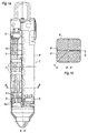
- Figure 1a shows in a section A-A in Figure 1b a boiling water fuel assembly.
- Figure 1b shows in a section B-B in Figure 1a the same fuel assembly.
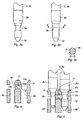
- Figure 2a shows, in a view from the side, a pressurized-water fuel assembly.
- Figure 2b shows, in a section C-C in Figure 2a, a bottom tie plate.
- Figure 3a shows, in a view from the side, an end plug with a first locking member.
- Figure 3b shows, in a view from the side, a bottom plug with an alternative embodiment of a first locking member.
- Figure 3c shows the first locking member in Figure 3b in a section D-D.
- Figure 4 shows, in a section from the side, two adjacently located plug holes in a bottom tie plate and a second locking member arranged in a locking hole arranged between the adjacently located plug holes in the bottom tie plate.
- Figure 5 shows an elongated element with an end plug which, with a second locking member arranged inserted into a first locking member, is locked to a bottom tie plate.
- Figure 6 shows an elongated element which, with an alternative embodiment of a second locking member arranged inserted into a first locking member, is locked to a bottom tie plate.
- Figure 7 shows an elongated element which, with an additional alternative embodiment of a second locking member arranged inserted into a first locking member, is locked to a bottom tie plate.
- Figure 8 shows, in a section from the side, two adjacently located plug holes in a bottom tie plate and an alternative embodiment of a second locking member arranged in a locking hole arranged between the adjacently located plug holes in the bottom tie plate.
- FIG. 1a shows a boiling water fuel assembly 1 which comprises a long tubular container, of substantially rectangular cross section, referred to as fuel channel 2.
- the fuel channel 2 is open at both ends so as to form a continuous flow passage through which the coolant of the reactor flows.
- the fuel assembly 1 comprises a large number of equally long tubular fuel rods 3, arranged in parallel in a bundle, in which pellets 4 of a nuclear fuel are arranged.
- the fuel rods 3 are arranged spaced from each other in four orthogonal sub-bundles by means of a cruciform support means 8 (see also Figure 1b).
- the respective sub-bundle of fuel rods 3 is retained at the top by a top tie plate 5 and at the bottom by a bottom tie plate 6.
- the fuel rods 3 in the respective sub-bundle are kept spaced apart from each other by means of spacers 7 and are prevented from bending or vibrating when the reactor is in operation.
- the bottom tie plate 6 comprises a plurality of through-holes 6a for passage of coolant. Further, the bottom tie plate 6 comprises a plurality of plug holes 6b for guiding the elongated elements 3, 3a with associated end plugs 3b (see Fig. 4).
- the rod which is arranged nearest the centre line is made as a part-length rod. The part-length rod extends from the bottom tie plate 6 and upwards through the fuel assembly 1 without reaching the top tie plate 5.
- Figures 2a, 2b show a fuel assembly 1 of pressurized-water type which comprises a number of elongated tubular fuel rods 3 and control rod guide tubes 3a, arranged in parallel.
- the fuel rods 3 accommodate pellets 4 of a nuclear fuel.
- the control rod guide tubes 3a are retained at the top by a top nozzle 5 and at the bottom by a bottom nozzle 6.
- the fuel rods 3 are kept spaced apart from each other by means of spacers 7.
- the holes in Figure 2b provided with centre lines are plug holes 6b for receiving elongated elements.
- the other holes 6a are intended for passage of coolant flow.
- Figure 3a shows in a view from the side an end plug 3b connected to an elongated element 3, 3a.
- the end plug 3b is provided with a first locking member in the form of a recess 9a in the form of a slot with a substantially spherical shape which extends around the periphery of the end plug.
- the lower part of the end plug 3b, designated 3c', may be provided with a bevelled edge to facilitate guiding of the end plug into the plug 6b in the bottom tie plate 6.
- Figure 3b shows an alternative embodiment of a first locking member 9b arranged in the end plug 3b.
- the first locking member is made as a recess in the form of a cavity with a substantially spherical shape.
- Figure 4 shows part of a bottom tie plate 6 which comprises two adjacently located plug holes 6b and a locking hole 6c extending between these plug holes 6b and opening out thereinto. Further, a second locking member 10 arranged in the locking hole 6c is shown.
- the second locking member 10 made as a substantially circular-cylindrical body 10a which is slidable in the axial direction of the locking hole 6c.
- Each end of the substantially circular-cylindrical body 10a is made with a radius and has a spherical shape 10b.
- Figure 5 shows how the locking plug 10 with its spherical end 10b cooperates with the recess 9a of an end plug 3b according to Figure 3a.
- the end plug 3b" which is to be locked in the plug hole 6b", that is in the plug hole 6b" shown on the righthand side in Figure 5
- the locking plug 10 is moved laterally through the locking hole 6c and partly into the plug hole 6b' which is shown on the lefthand side in Figure 5.
- an adjacently located end plug 3b' is inserted into the plug hole 6b'.
- the end plug 3b' pushes the locking plug 10 in the opposite direction through the locking hole 6c such that it is arranged, with its spherical end 10b, in the spherical recess 9a in the end plug 3b".
- one of the end plug 3b" is locked to the bottom tie plate 6 whereas the other end plug 3b' is arranged guided in the bottom tie plate 6.
- the end plug 3b may be locked so as to prevent rotation in the bottom tie plate 6. Prevention of rotation in the bottom tie plate 6 is desirable, especially when it is a question of locking of spacer holder rods.
- a locking pin 11 may be arranged from one of the flat surfaces of the bottom tie plate, in Figures 4 and 5 shown from the upper flat surface and at an angle to the locking plug 10.
- the locking pin 11 may be fixed to the bottom tie plate 6, for example by welding, and is arranged to extend into the locking hole 6c such that the possible displacement of the locking plug 10 between two adjacently located plug holes 6b is limited to a distance which may correspond to the length of a part 10c of the circular-cylindrical body 10a of the locking plug which is provided with a smaller diameter than the rest of the body 10a.
- the locking plug 10 is suitably placed protected inside the bottom tie plate and is advantageously made of stainless steel, which is good from the point of view of corrosion.
- the locking plug 10 is made of a nickel-base alloy, for example Inconel.
- the first and second locking members 9a, 9b, 10 need not, of course, be made with spherical surfaces.
- the surface may have an arbitrary double-curved shape, a plane shape, or a bevelled shape.
- the essential point is that the concave shape of the first locking member 9a, 9b may cooperate with the shape of the second locking member 10 for locking the end plug 3b" to the bottom tie plate 6.
- the locking plug 10 is thus provided at each end with surfaces which are suitable for cooperation with the first locking member 9a, 9b in that end plug 3b which it is to lock and to facilitate dismantling thereof from the bottom tie plate 6.
- Figure 6 shows a locking plug 10 which at each end is provided with bevelled edges designated 10d.
- the end plug 3b" which is to be locked is provided with a waist with corresponding bevelled edges designated 3c" to cooperate with the locking plug 10.
- Figure 7 shows a locking plug 10 which at each end is provided with plane end surfaces designated 10e.
- the end plug 3b" which is to be locked is provided with a waist with corresponding plane surfaces to cooperate with the locking plug 10.
- the end plug 3b" is further provided with a bevelled edge 3d.
- Figures 5, 6 and 7 show the end plug 3b" with a bevelled edge designated 3e for cooperation with a bevelled edge 6d formed in the bottom tie plate in connection with the mounting of the elongated elements 3, 3a in the bottom tie plate 6.
- Figure 8 shows a locking plug 10, the diameter of which substantially corresponds to the diameter of the locking hole 6c. Further, it is shown that a hole for insertion of the locking plug 10 into the bottom tie plate is plugged up (see reference numeral 12). The hole may, for example, be welded up after the locking plug 10 has been inserted into the locking hole 6c. In this way, particles in the coolant are prevented from entering the locking hole 6c, thus causing possible seizing between the locking plug 10 and the locking hole 6c. Plugging of the hole also ensures that the locking plug 10 does not leave the bottom tie plate 6.
Landscapes
- Physics & Mathematics (AREA)
- Engineering & Computer Science (AREA)
- Plasma & Fusion (AREA)
- General Engineering & Computer Science (AREA)
- High Energy & Nuclear Physics (AREA)
- Monitoring And Testing Of Nuclear Reactors (AREA)
- Structure Of Emergency Protection For Nuclear Reactors (AREA)
- Fuel-Injection Apparatus (AREA)
- Heat-Exchange Devices With Radiators And Conduit Assemblies (AREA)
Claims (10)
- Brennelement (1) für einen leichtwasser-gekühlten Kernreaktor, zu welchem Brennelement ein erstes und ein zweites Verschlußglied (9a,9b,10) und eine Vielzahl von langgestreckten Elementen (3,3a) gehören, wobei jedes untere Ende der langgestreckten Elemente mit einem Endzapfen (3b) versehen ist, und der Endzapfen (3b) zur Führung oder Verriegelung in einer Endplatte (6) angeordnet ist, die mindestens zwei benachbart positionierte Zapfenlöcher (6b) für die Aufnahme je eines Endzapfens (3b) hat, dadurch gekennzeichnet, daß das erste Verschlußglied (9a,9b) aus einer Ausnehmung in einem Endzapfen (3b) besteht, das zweite Verschlußglied (10) verschiebbar in einem Verschlußloch (6c) angeordnet ist, welc:hes sich zwischen den beiden benachbart positionierten Zapfenlöchern (6b) erstreckt und an den Zapfenlöchern mündet, wobei das zweite Verschlußglied (10) eine Länge hat, die sich über die Länge des Verschlußloches (6c) erstreckt, und Endflächen mit einer Gestalt hat, die zum Zusammenwirken mit dem ersten Verschlußglied (9a,9b) bestimmt sind.
- Brennelement (1) nach Anspruch 1, dadurch gekennzeichnet, daß das erste Verschlußglied (9a,9b) sich um die Peripherie des Endzapfens (3d) erstreckt.
- Brennelement (1) nach Anspruch 1 oder 2, dadurch gekennzeichnet, daß das erste Verschlußglied (9a,9b) eine im wesentlichen konkave Form hat.
- Brennelement (1) nach Anspruch 1 oder 2, dadurch gekennzeichnet, daß das erste Verschlußglied (9a,9b) eine im wesentlichen sphärische Form hat.
- Brennelement (1) nach Anspruch 3, dadurch gekennzeichnet, daß das zweite Verschlußglied (10) als ein im wesentlichen zylindrischer Körper (10a ausgebildet ist, dessen beide Enden eine konvexe (10b) Form haben.
- Brennelement (1) nach Anspruch 5, dadurch gekennzeichnet, daß mindestens ein Ende des zweiten Verschlußgliedes (10) eine im wesentlichen sphärische Form (10b) hat.
- Brennelement (1) nach Anspruch 1, dadurch gekennzeichnet, daß das zweite Verschlußglied (10) als ein im wesentlichen zylindrischer Körper (10a) mit zwei Enden ausgebildet ist, von denen mindestens ein Ende eine ebene Form (10e) hat.
- Brennelement (1) nach Anspruch 1, dadurch gekennzeichnet, daß das zweite Verschlußglied (10) als ein im wesentlichen zylindrischer Körper (10a) mit zwei Enden ausgebildet ist, von denen mindestens ein Ende eine sich verjüngende Form (10d) hat.
- Brennelement (1) nach Anspruch 1, dadurch gekennzeichnet, daß das zweite Verschlußglied (10) einen im Durchmesser verkleinerten Abschnitt (10c) des zylindrischen Körpers (10a) hat für das Zusammenwirken mit einem Verschlußstift (11) zur Begrenzung der Beweglichkeit des zweiten Verschlußgliedes (10) in dem Verschlußloch (6c).
- Verfahren zur Befestigung eines langgestreckten Elementes (3,3a) mit einem zugehörigen Endzapfen (3b) in einer Endplatte (6) in einem Brennelement (1) für einen leichtwasser-gekühlten Kernreaktor, wobei die Befestigung durch ein Zusammenwirken zwischen einem ersten und einem zweiten Verschlußglied (9a,9b,10) erreicht wird und wobei die Endplatte mit mindestens zwei benachbart positionierten Verschlußlöchern (6b) zur Aufnahme je eines Endzapfens (3b) versehen ist, gekennzeichnet durch folgende Verfahrensschritte:Anordnung eines Verschlußloches (6c), welches sich zwischen den beiden benachbart positionierten Zapfenlöchern (6b) erstreckt und an diesen mündet,Anordnung eines zweiten Verschlußgliedes (10) in dem Verschlußloch (6c),Einführung eines Endzapfen (3b''), welcher das erste Verschlußglied (9a,9b) enthält, in das Zapfenloch (6b''),falls notwendig, Verschiebung des zweiten Verschlußgliedes (10), welches eine Länge hat, die größer als die Länge des Verschlußloches (6c) ist, in einer Richtung in dem Verschlußloch (6c) durch den Endzapfen (3b'') in der Weise, daß die Einführung des Endzapfen 3b'' möglich ist,Einführung eines Endzapfen (3b') in das benachbart positionierte Zapfenloch (6b'), wobei das zweite Verschlußglied (10) veranlaßt wird, sich in der Weise in eine Richtung zu verschieben, daß es zum Zusammenwirken mit dem ersten Verschlußglied (9a,9b) gebracht wird.
Applications Claiming Priority (3)
| Application Number | Priority Date | Filing Date | Title |
|---|---|---|---|
| SE9700855 | 1997-03-11 | ||
| SE9700855A SE508875C2 (sv) | 1997-03-11 | 1997-03-11 | Anordning och förfarande för låsning av stavar i bottenplattan på en bränslepatron |
| PCT/SE1998/000383 WO1998040894A1 (en) | 1997-03-11 | 1998-03-04 | Device and method for locking rods in a bottom tie plate of a fuel assembly |
Publications (2)
| Publication Number | Publication Date |
|---|---|
| EP0966745A1 EP0966745A1 (de) | 1999-12-29 |
| EP0966745B1 true EP0966745B1 (de) | 2002-07-31 |
Family
ID=20406092
Family Applications (1)
| Application Number | Title | Priority Date | Filing Date |
|---|---|---|---|
| EP98909903A Expired - Lifetime EP0966745B1 (de) | 1997-03-11 | 1998-03-04 | Vorrichtung und verfahren zur befestigung von stangen an einer bodentrageplatte eines kernbrennstoffbündels |
Country Status (7)
| Country | Link |
|---|---|
| US (1) | US6310931B1 (de) |
| EP (1) | EP0966745B1 (de) |
| JP (1) | JP3955104B2 (de) |
| DE (1) | DE69806911T2 (de) |
| ES (1) | ES2180149T3 (de) |
| SE (1) | SE508875C2 (de) |
| WO (1) | WO1998040894A1 (de) |
Families Citing this family (17)
| Publication number | Priority date | Publication date | Assignee | Title |
|---|---|---|---|---|
| SE518705C2 (sv) * | 2001-03-20 | 2002-11-05 | Westinghouse Atom Ab | Filter och bränslepatron för en nukleär anläggning av lättvattentyp |
| RU2236712C2 (ru) * | 2002-10-24 | 2004-09-20 | Открытое акционерное общество "Машиностроительный завод" | Регулирующая тепловыделяющая сборка водо-водяного энергетического реактора |
| FR2864323B1 (fr) * | 2003-12-22 | 2008-07-18 | Framatome Anp | Embout d'extremite d'assemblage de combustible a moyens de maintien des extremites des crayons et assemblage correspondant |
| FR2864324B1 (fr) * | 2003-12-22 | 2008-07-18 | Framatome Anp | Embout d'extremite pour assemblage combustible a nez d'orientation de l'ecoulement du fluide refrigerant et assemblage correspondant |
| EP1748938B1 (de) * | 2004-05-06 | 2008-06-11 | Rexam Dispensing SMT | Verschlussvorrichtung für einen nichtentlüfteten flüssigproduktspender |
| US8116423B2 (en) | 2007-12-26 | 2012-02-14 | Thorium Power, Inc. | Nuclear reactor (alternatives), fuel assembly of seed-blanket subassemblies for nuclear reactor (alternatives), and fuel element for fuel assembly |
| CN101911211B (zh) | 2007-12-26 | 2014-02-12 | 钍能源股份有限公司 | 核反应堆(可选的)、用于核反应堆(可选的)的点火区-再生区子组件的燃料组件和用于燃料组件的燃料元件 |
| EP3032541B1 (de) | 2008-12-25 | 2019-02-20 | Thorium Power, Inc. | Brennelement und verfahren zur herstellung eines brennelements für ein kernreaktorbrennstabbündel |
| US10192644B2 (en) | 2010-05-11 | 2019-01-29 | Lightbridge Corporation | Fuel assembly |
| WO2011143172A1 (en) | 2010-05-11 | 2011-11-17 | Thorium Power, Inc. | Fuel assembly with metal fuel alloy kernel and method of manufacturing thereof |
| US10170207B2 (en) | 2013-05-10 | 2019-01-01 | Thorium Power, Inc. | Fuel assembly |
| WO2013180776A1 (en) * | 2012-04-17 | 2013-12-05 | Babcock & Wilcox Mpower, Inc. | Lower end fitting locating pins |
| ITUA20163713A1 (it) * | 2016-05-04 | 2017-11-04 | Luciano Cinotti | Reattore nucleare con nocciolo autoportante |
| US10818402B2 (en) | 2017-03-31 | 2020-10-27 | Westinghouse Electric Company Llc | Spacer grid using tubular cells with mixing vanes |
| US10720246B2 (en) * | 2017-04-20 | 2020-07-21 | Westinghouse Electric Company Llc | Fuel assembly arrangement for retaining fuel rod end plug to bottom nozzle |
| CN107658035B (zh) * | 2017-09-29 | 2019-06-25 | 中国核动力研究设计院 | 一种限位板结构、上部堆内构件及吊篮组件 |
| CN115274161A (zh) * | 2022-07-14 | 2022-11-01 | 中广核工程有限公司 | 反应堆堆芯测量仪表导向组件 |
Family Cites Families (11)
| Publication number | Priority date | Publication date | Assignee | Title |
|---|---|---|---|---|
| US3769158A (en) * | 1971-11-24 | 1973-10-30 | Nuclear Fuel Services | End fitting retainer for nuclear fuel assembly |
| FR2266262B1 (de) * | 1974-03-28 | 1976-12-17 | Commissariat Energie Atomique | |
| US4344915A (en) * | 1980-09-17 | 1982-08-17 | The United States Of America As Represented By The United States Department Of Energy | Nuclear reactor fuel rod attachment system |
| US4492668A (en) * | 1982-04-08 | 1985-01-08 | Westinghouse Electric Corp. | Apparatus and method for preventing the rotation of rods used in nuclear _fuel assemblies |
| US4818473A (en) | 1985-05-08 | 1989-04-04 | Westinghouse Electric Corp. | Fuel bundle |
| US4919883A (en) * | 1988-12-14 | 1990-04-24 | Combustion Engineering, Inc. | Lower end fitting debris collector and end cap spacer grid |
| WO1992005565A1 (de) * | 1990-09-18 | 1992-04-02 | Siemens Aktiengesellschaft | Brennelement mit gesicherten stabenden am fuss |
| SE469046B (sv) * | 1991-02-11 | 1993-05-03 | Asea Atom Ab | Braenslepatron foer en kaernreaktor av laettvattentyp |
| US5553108A (en) * | 1994-11-03 | 1996-09-03 | General Electric Company | Water rod attachment in a nuclear reactor fuel bundle |
| US5481579A (en) * | 1995-01-30 | 1996-01-02 | General Electric Company | Latching and lifting mechanism for a nuclear reactor fuel bundle |
| US5748695A (en) * | 1995-11-07 | 1998-05-05 | General Electric Company | Fuel assembly structure selectively using channel and coolant rod for load support and method |
-
1997
- 1997-03-11 SE SE9700855A patent/SE508875C2/sv not_active IP Right Cessation
-
1998
- 1998-03-04 ES ES98909903T patent/ES2180149T3/es not_active Expired - Lifetime
- 1998-03-04 US US09/367,827 patent/US6310931B1/en not_active Expired - Lifetime
- 1998-03-04 WO PCT/SE1998/000383 patent/WO1998040894A1/en not_active Ceased
- 1998-03-04 JP JP53950298A patent/JP3955104B2/ja not_active Expired - Lifetime
- 1998-03-04 DE DE69806911T patent/DE69806911T2/de not_active Expired - Lifetime
- 1998-03-04 EP EP98909903A patent/EP0966745B1/de not_active Expired - Lifetime
Also Published As
| Publication number | Publication date |
|---|---|
| US6310931B1 (en) | 2001-10-30 |
| EP0966745A1 (de) | 1999-12-29 |
| WO1998040894A1 (en) | 1998-09-17 |
| DE69806911D1 (de) | 2002-09-05 |
| JP2001514753A (ja) | 2001-09-11 |
| SE9700855L (sv) | 1998-09-12 |
| DE69806911T2 (de) | 2003-05-08 |
| ES2180149T3 (es) | 2003-02-01 |
| SE508875C2 (sv) | 1998-11-09 |
| SE9700855D0 (sv) | 1997-03-11 |
| JP3955104B2 (ja) | 2007-08-08 |
Similar Documents
| Publication | Publication Date | Title |
|---|---|---|
| US6310931B1 (en) | Device and method for locking rods in a bottom tie plate of a fuel assembly | |
| EP0243917B1 (de) | Kernbrennstabbündel | |
| EP1012852B1 (de) | Kerbrennstoffeinheit | |
| US4420458A (en) | Nuclear fuel assembly with coolant conducting tube | |
| JPS62177487A (ja) | 大径の冷却材案内管を有する核燃料集合体 | |
| EP0146806A2 (de) | Kernreaktor | |
| US7856076B2 (en) | Terminal end-piece for a fuel assembly having a nose for orienting the flow of coolant fluid and corresponding assembly | |
| SE503626C2 (sv) | Värmebränsleelement och förfarande för låsning av distanshållare i ett sådant | |
| JP2521015B2 (ja) | 沸騰水型原子炉用の核燃料バンドル | |
| JPS5872097A (ja) | 原子炉の燃料アセンブリ | |
| JPH0463353B2 (de) | ||
| EP0797217B1 (de) | Vorrichtung zur Befestigung eines Abstandhalters auf einem Wasserrohr mit nicht-rundem Querschnitt | |
| US5363423A (en) | Quick release top nozzle assembly | |
| US4752438A (en) | Cluster guide with centering and antivibratory positioning device for nuclear reactors | |
| KR910005731B1 (ko) | 원자로용 연료 집합체 | |
| JPH0215840B2 (de) | ||
| US5896436A (en) | Fuel assembly for a boiling water reactor | |
| US5483565A (en) | Fuel assembly for a boiling water reactor | |
| US5802127A (en) | Device for protecting in-core monitors against damage during servicing of nuclear reactor | |
| EP0897581B1 (de) | Brennstabbündel für siedewasserreaktor | |
| JP3742698B2 (ja) | 荷重支持にチャネルまたは冷却材棒を選択的に用いる燃料集合体構造および方法 | |
| EP0201859A1 (de) | Brennstabbündel für den Einsatz in einem Kernreaktor | |
| JPH09166676A (ja) | 荷重支持にチャネルを用いる燃料集合体構造および方法 | |
| JPH0352595B2 (de) | ||
| EP1012851B1 (de) | Kernbrennstoffeinheit |
Legal Events
| Date | Code | Title | Description |
|---|---|---|---|
| PUAI | Public reference made under article 153(3) epc to a published international application that has entered the european phase |
Free format text: ORIGINAL CODE: 0009012 |
|
| 17P | Request for examination filed |
Effective date: 19991007 |
|
| AK | Designated contracting states |
Kind code of ref document: A1 Designated state(s): DE ES SE |
|
| RAP1 | Party data changed (applicant data changed or rights of an application transferred) |
Owner name: WESTINGHOUSE ATOM AB |
|
| GRAG | Despatch of communication of intention to grant |
Free format text: ORIGINAL CODE: EPIDOS AGRA |
|
| RTI1 | Title (correction) |
Free format text: DEVICE AND METHOD FOR LOCKING RODS IN A BOTTOM TIE PLATE OF A NUCLEAR FUEL ASSEMBLY |
|
| RTI1 | Title (correction) |
Free format text: DEVICE AND METHOD FOR LOCKING RODS IN A BOTTOM TIE PLATE OF A NUCLEAR FUEL ASSEMBLY |
|
| 17Q | First examination report despatched |
Effective date: 20011109 |
|
| GRAG | Despatch of communication of intention to grant |
Free format text: ORIGINAL CODE: EPIDOS AGRA |
|
| GRAH | Despatch of communication of intention to grant a patent |
Free format text: ORIGINAL CODE: EPIDOS IGRA |
|
| GRAH | Despatch of communication of intention to grant a patent |
Free format text: ORIGINAL CODE: EPIDOS IGRA |
|
| GRAA | (expected) grant |
Free format text: ORIGINAL CODE: 0009210 |
|
| AK | Designated contracting states |
Kind code of ref document: B1 Designated state(s): DE ES SE |
|
| REF | Corresponds to: |
Ref document number: 69806911 Country of ref document: DE Date of ref document: 20020905 |
|
| PG25 | Lapsed in a contracting state [announced via postgrant information from national office to epo] |
Ref country code: SE Free format text: LAPSE BECAUSE OF FAILURE TO SUBMIT A TRANSLATION OF THE DESCRIPTION OR TO PAY THE FEE WITHIN THE PRESCRIBED TIME-LIMIT Effective date: 20021031 |
|
| REG | Reference to a national code |
Ref country code: ES Ref legal event code: FG2A Ref document number: 2180149 Country of ref document: ES Kind code of ref document: T3 |
|
| PLBE | No opposition filed within time limit |
Free format text: ORIGINAL CODE: 0009261 |
|
| STAA | Information on the status of an ep patent application or granted ep patent |
Free format text: STATUS: NO OPPOSITION FILED WITHIN TIME LIMIT |
|
| 26N | No opposition filed |
Effective date: 20030506 |
|
| REG | Reference to a national code |
Ref country code: DE Ref legal event code: R082 Ref document number: 69806911 Country of ref document: DE Representative=s name: WEICKMANN & WEICKMANN PATENT- UND RECHTSANWAEL, DE Ref country code: DE Ref legal event code: R082 Ref document number: 69806911 Country of ref document: DE Representative=s name: WEICKMANN & WEICKMANN PATENTANWAELTE - RECHTSA, DE Ref country code: DE Ref legal event code: R082 Ref document number: 69806911 Country of ref document: DE Representative=s name: PATENTANWAELTE WEICKMANN & WEICKMANN, DE Ref country code: DE Ref legal event code: R082 Ref document number: 69806911 Country of ref document: DE Representative=s name: WEICKMANN & WEICKMANN, DE Ref country code: DE Ref legal event code: R082 Ref document number: 69806911 Country of ref document: DE Representative=s name: HANSMANN & VOGESER, DE |
|
| REG | Reference to a national code |
Ref country code: DE Ref legal event code: R082 Ref document number: 69806911 Country of ref document: DE Representative=s name: WEICKMANN & WEICKMANN PATENT- UND RECHTSANWAEL, DE Ref country code: DE Ref legal event code: R082 Ref document number: 69806911 Country of ref document: DE Representative=s name: WEICKMANN & WEICKMANN PATENTANWAELTE - RECHTSA, DE Ref country code: DE Ref legal event code: R082 Ref document number: 69806911 Country of ref document: DE Representative=s name: PATENTANWAELTE WEICKMANN & WEICKMANN, DE |
|
| PGFP | Annual fee paid to national office [announced via postgrant information from national office to epo] |
Ref country code: DE Payment date: 20170320 Year of fee payment: 20 |
|
| PGFP | Annual fee paid to national office [announced via postgrant information from national office to epo] |
Ref country code: ES Payment date: 20170328 Year of fee payment: 20 |
|
| REG | Reference to a national code |
Ref country code: DE Ref legal event code: R071 Ref document number: 69806911 Country of ref document: DE |
|
| REG | Reference to a national code |
Ref country code: ES Ref legal event code: FD2A Effective date: 20200903 |
|
| PG25 | Lapsed in a contracting state [announced via postgrant information from national office to epo] |
Ref country code: ES Free format text: LAPSE BECAUSE OF EXPIRATION OF PROTECTION Effective date: 20180305 |