EP0966909A2 - Appareil de cuisine avec un bol de mixage et un mécanisme d'entraínement pour un outil de mixage dans le bol - Google Patents
Appareil de cuisine avec un bol de mixage et un mécanisme d'entraínement pour un outil de mixage dans le bol Download PDFInfo
- Publication number
- EP0966909A2 EP0966909A2 EP99118360A EP99118360A EP0966909A2 EP 0966909 A2 EP0966909 A2 EP 0966909A2 EP 99118360 A EP99118360 A EP 99118360A EP 99118360 A EP99118360 A EP 99118360A EP 0966909 A2 EP0966909 A2 EP 0966909A2
- Authority
- EP
- European Patent Office
- Prior art keywords
- food processor
- mixing vessel
- agitator
- heating
- speed
- Prior art date
- Legal status (The legal status is an assumption and is not a legal conclusion. Google has not performed a legal analysis and makes no representation as to the accuracy of the status listed.)
- Granted
Links
Images

Classifications
-
- A—HUMAN NECESSITIES
- A47—FURNITURE; DOMESTIC ARTICLES OR APPLIANCES; COFFEE MILLS; SPICE MILLS; SUCTION CLEANERS IN GENERAL
- A47J—KITCHEN EQUIPMENT; COFFEE MILLS; SPICE MILLS; APPARATUS FOR MAKING BEVERAGES
- A47J36/00—Parts, details or accessories of cooking-vessels
- A47J36/16—Inserts
-
- A—HUMAN NECESSITIES
- A47—FURNITURE; DOMESTIC ARTICLES OR APPLIANCES; COFFEE MILLS; SPICE MILLS; SUCTION CLEANERS IN GENERAL
- A47J—KITCHEN EQUIPMENT; COFFEE MILLS; SPICE MILLS; APPARATUS FOR MAKING BEVERAGES
- A47J27/00—Cooking-vessels
- A47J27/004—Cooking-vessels with integral electrical heating means
-
- A—HUMAN NECESSITIES
- A47—FURNITURE; DOMESTIC ARTICLES OR APPLIANCES; COFFEE MILLS; SPICE MILLS; SUCTION CLEANERS IN GENERAL
- A47J—KITCHEN EQUIPMENT; COFFEE MILLS; SPICE MILLS; APPARATUS FOR MAKING BEVERAGES
- A47J27/00—Cooking-vessels
- A47J27/14—Cooking-vessels for use in hotels, restaurants, or canteens
-
- A—HUMAN NECESSITIES
- A47—FURNITURE; DOMESTIC ARTICLES OR APPLIANCES; COFFEE MILLS; SPICE MILLS; SUCTION CLEANERS IN GENERAL
- A47J—KITCHEN EQUIPMENT; COFFEE MILLS; SPICE MILLS; APPARATUS FOR MAKING BEVERAGES
- A47J36/00—Parts, details or accessories of cooking-vessels
- A47J36/16—Inserts
- A47J36/165—Stirring devices operatively connected to cooking vessels when being removably inserted inside
-
- A—HUMAN NECESSITIES
- A47—FURNITURE; DOMESTIC ARTICLES OR APPLIANCES; COFFEE MILLS; SPICE MILLS; SUCTION CLEANERS IN GENERAL
- A47J—KITCHEN EQUIPMENT; COFFEE MILLS; SPICE MILLS; APPARATUS FOR MAKING BEVERAGES
- A47J36/00—Parts, details or accessories of cooking-vessels
- A47J36/32—Time-controlled igniting mechanisms or alarm devices
-
- A—HUMAN NECESSITIES
- A47—FURNITURE; DOMESTIC ARTICLES OR APPLIANCES; COFFEE MILLS; SPICE MILLS; SUCTION CLEANERS IN GENERAL
- A47J—KITCHEN EQUIPMENT; COFFEE MILLS; SPICE MILLS; APPARATUS FOR MAKING BEVERAGES
- A47J43/00—Implements for preparing or holding food, not provided for in other groups of this subclass
- A47J43/04—Machines for domestic use not covered elsewhere, e.g. for grinding, mixing, stirring, kneading, emulsifying, whipping or beating foodstuffs, e.g. power-driven
- A47J43/046—Machines for domestic use not covered elsewhere, e.g. for grinding, mixing, stirring, kneading, emulsifying, whipping or beating foodstuffs, e.g. power-driven with tools driven from the bottom side
-
- G—PHYSICS
- G05—CONTROLLING; REGULATING
- G05D—SYSTEMS FOR CONTROLLING OR REGULATING NON-ELECTRIC VARIABLES
- G05D23/00—Control of temperature
- G05D23/19—Control of temperature characterised by the use of electric means
- G05D23/1902—Control of temperature characterised by the use of electric means characterised by the use of a variable reference value
-
- G—PHYSICS
- G05—CONTROLLING; REGULATING
- G05D—SYSTEMS FOR CONTROLLING OR REGULATING NON-ELECTRIC VARIABLES
- G05D23/00—Control of temperature
- G05D23/19—Control of temperature characterised by the use of electric means
- G05D23/1951—Control of temperature characterised by the use of electric means with control of the working time of a temperature controlling device
-
- A—HUMAN NECESSITIES
- A47—FURNITURE; DOMESTIC ARTICLES OR APPLIANCES; COFFEE MILLS; SPICE MILLS; SUCTION CLEANERS IN GENERAL
- A47J—KITCHEN EQUIPMENT; COFFEE MILLS; SPICE MILLS; APPARATUS FOR MAKING BEVERAGES
- A47J43/00—Implements for preparing or holding food, not provided for in other groups of this subclass
- A47J43/04—Machines for domestic use not covered elsewhere, e.g. for grinding, mixing, stirring, kneading, emulsifying, whipping or beating foodstuffs, e.g. power-driven
- A47J43/07—Parts or details, e.g. mixing tools, whipping tools
- A47J43/08—Driving mechanisms
Definitions
- the invention relates to a food processor with a Stirring vessel and a drive for an agitator in the Stirring vessel, the stirring vessel in its lower area is heatable.
- Such a kitchen machine is, for example, from the DOS 35 072 76 known.
- Well-known kitchen machines come here however always quickly to their limits, since a very high one Power consumption and thus a strong warming of the Motors goes hand in hand.
- the object of the present invention is a how Food processor specified in the beginning in an advantageous Way to train.
- an agitator setting (Dough stirring circuit) is provided, in which stirring phases are interrupted by regular downtimes.
- This dough stirring circuit can be set using the setting switch are switched for the speed of the agitator, an embodiment is preferred here in which a setting in the dough mixing of one Zero position counterclockwise and a usual setting of the agitator clockwise he follows. This ensures that a Switching from the dough agitator circuit to a normal circuit, d. H. a setting of a constant Speed of the agitator, only with one run over Zeroing can take place.
- This dough mixer is characterized by stirring phases interrupted by resting phases from ("Stop and go").
- the drive is a universal motor or series motor.
- the drive unit must meet both the requirements for the high speeds as well Apply high torque for heavy loads. Solutions are known in which sufficient strong motors with direct drive are used, whose characteristics are designed so that the required Conditions regarding speed and torque met be without doing the prescribed exceed thermal limits. Disadvantageous this embodiment is that the kidney trained is what also leads to an increase in volume and an increase in the weight of the engine. Known are known per se for cooling such motors Cooling fan provided.
- the drive unit is the subject of the invention formed such that this from an engine and a gearbox with a fixed gear ratio, where the motor with appropriate control, which via the Characteristics of the engine and the gear ratio is designed so that the entire required speed range with a basic or normal load, as in the predominant use of the device is present, electronically is driven through in a controlled manner and at one for the Device application maximum predetermined load (e.g. Dough stirring circuit), which is used less often, the motor is controlled uncontrolled and the output required to perform the required Brings up work.
- the one for use of the drive unit prescribed thermal limits are adhered to.
- a stationary universal motor (series motor) via a belt that runs parallel to the engine arranged agitator drives.
- the motor is powered by mains supplied and controlled via a triac.
- the drive motor has no cooling fan on its shaft. Rather, an external one is used to cool the drive motor electric blower motor provided.
- At a Base or normal load is the engine within its Characteristic curve through phase control to the required Regulated speeds.
- the losses of the power output especially at high speeds due to elimination of a cooling fan on the motor shaft is reduced.
- For the cooling is provided by the external cooling fan, whereby the air output of the heat development in the engine, measured from a temperature sensor in the engine, by electronic Regulation is adjusted.
- the air performance is at adapted to a base load for each speed, the values come from empirical investigations. With increased Load must reach the motor voltage to reach the target speed increased by controlling the triac accordingly become.
- This increase is called a deviation from the tension evaluated at base load and can indirectly as Load increase can be interpreted.
- the engine temperature rises due to the increased losses in the copper windings over the prescribed limit value.
- the per se maximum speed of 11,500 rpm a speed of 100 to 3,000, on average approx. 500 RPM reduced.
- the drive unit consisting of Engine and transmission, is designed so that the maximum intended load for the use of the device a sufficient rotational movement for circulation Production of dough or the like is guaranteed is.
- the external fan generates during this operating mode the maximum air output, however, alone not enough to use the engine among those prescribed temperature limit cool.
- the engine will handle the high loads only controlled with pulses, the full Mains voltage is kept and become a burden sets the appropriate speed.
- the duration (pulse width) the control pulse must be sufficient to the maximum intended for the use of the device To do the necessary work.
- the Ratio of the pulse width of the control pulse for the Motor at the subsequent off time is set so that at maximum air flow of the external cooling fan and at the maximum intended load for a certain duration for the use of the device prescribed limit temperature of the motor windings is not exceeded.
- a universal motor (series motor) runs the Motor in pulse mode with every start-up with the maximum available torque from a standstill, causing one for certain Applications useful breakaway effect.
- the production of yeast dough or the like carries the impulse operation by shaking loose dough components an improvement in the return of the dough mixture in the working area of the kneading tool in the mixing bowl.
- the standstills in the Comparison to the stirring phases over a multiple period of time extend.
- the resting phase which is preferred about is three times as long as the stirring phase, for example about 4.5 seconds compared to 1.5 seconds is too advantageous in that they are used for engine cooling can be. They are relationships of the resting phase conceivable for the stirring phase in the range from 1: 1 to 6: 1.
- the dough stirring circuit can only be activated if the heating temperature below a certain limit temperature, for example 70 ° C is preset.
- This security function is also in a so-called turbo function, at which very high speeds can be achieved in the short term, conceivable.
- the dependence on a certain one Limit temperature has in particular the background that already local at temperatures above 70 ° C Boiling phenomena can occur, which are caused by the Stirring function are increased (delay in boiling). This can at very high speeds, which both at a Dough stirring circuit as well as in a turbo circuit can be achieved, then lead to a very strong pressure builds up, which leads to a lifting of a lid arranged on the mixing vessel can.
- a start up of the agitator to this speed first slowly and then faster.
- the training should be chosen so that a speed of the agitator up to about 1000 revolutions there is always a slow start-up per minute.
- a speed of the agitator up to about 1000 revolutions there is always a slow start-up per minute.
- there is a jerky Start off at higher set speeds, above about 1000 revolutions per minute, there is a jerky Start off.
- the speed change of the Motors in normal operation i.e. at constant speed of the agitator, preferably done without a gear.
- the change is controlled by means of made the leading edge angle.
- High speeds of more than 1,000 rpm in most applications set to crush the pot content. You need the maximum torque of the motor to wedge the mixing tool when starting to avoid in the medium.
- the one available Drive motor can only get the maximum torque at maximum Apply supply voltage, d. H. without leading edge start and then adjust to the target speed. Lower speeds of less than 1,000 rpm will be mainly used for stirring in cooking. Here a crushing of the pot content must be avoided in which the motor with a lower supply voltage (maximum leading edge) started and then on the target speed is regulated.
- the speed control is implemented programmatically via a microprocessor.
- the setpoint is infinitely variable via a Potentiometer, the feedback on the respective Actual value is done by a sensor that detects the rotary movements of the motor on the motor shaft.
- the interpretation the components determining the control loop be such that a control range of at least 1: 100 is reached, i.e. H. Speeds of z. B. 100 to approx. 10,000 rpm on the mixing tool.
- the invention further relates to a food processor with a mixing vessel and a drive for an agitator in the mixing vessel, the mixing vessel in its lower Is heated and the speed and / or the Temperature via illuminated switches, for example Rotary or slide switch takes place.
- a food processor with a mixing vessel and a drive for an agitator in the mixing vessel, the mixing vessel in its lower Is heated and the speed and / or the Temperature via illuminated switches, for example Rotary or slide switch takes place.
- Even those trained Food processors are known.
- LED displays for temperature and / or Speed are formed in two colors, for example yellow and red.
- Light emitting components such as B. LEDs feed light from opposite directions a light guide. The light guide is like this designed that light perpendicular to the direction of the feed is emitted and so the effect of a light bar arises.
- the feed components can either be the intensity of shifted one side of the light bar to the other and will be increased (with feed components of the same color) or with differently colored feed components an effect of fluid change from the color of one feed component via mixed light down to the color of the other feed component become.
- the speed can be double colored Infeed of a low speed a corresponding one Intensity assigned and displayed and when increasing the speed setting the intensity to the other Be shifted towards the end of the light bar or increased. While at lower setting ranges the yellow LEDs are strongly activated, the red ones only weak, takes place with increasingly higher settings a weakening of the activation of the yellow and one Enhancement of the activation of the red LEDs.
- the illuminated Scale fields around the switches (potentiometers) thus have a signal function for the user, especially with higher setting values.
- the stirring vessel in its lower area can be heated and a rotary switch, especially for a built-in electronic clock, for example to preselect a heating time is to design the rotary switch so that by a high speed of rotation of the rotary switch a certain angle of rotation a large unit of time for example one minute, and a lower one Rotational speed of the rotary switch above the same Angle of rotation a low unit of time, for example a second that is assignable.
- the clock is adjusted via the same angle of rotation in small as well as in large steps possible without drive through the entire setting range have to.
- Such an interface can also be used be used that part of a calibration circuit with regard to each removal loop of an electrical / electronic Component of the food processor in a removable / pluggable Additional part is formed. It exists thus the possibility via this interface after the Device manufacturing to set device-specific values or to calibrate. In this way it can be expensive electrical / mechanical adjustment processes and corresponding no electrical / mechanical components become.
- the respective, device-specific values are thereby in a non-volatile memory (EEPROM) in the electronics of the device and can be stored in the Service case to be changed. E.g. can with such Calibration the balance device can be adjusted and the target speeds with the actual speeds of the Agitator are compared. Corresponding deviations could be stored in your non-volatile memory become.
- EEPROM non-volatile memory
- the plug part with regard to the calibration values as well is programmable.
- the plug part can, for example, in the form a dongle, which is factory-made is programmed. With the help of this connector, which placed on the interface of the food processor calibrations are carried out and if necessary Presets, e.g. the scale, the speeds, etc., changed.
- Presets e.g. the scale, the speeds, etc.
- the Calibration using the connector part in several Steps take place, each step, for example, in one Time display is shown. Further, for example, in the respective setting values on the weight display are displayed. It is proposed that, for example, in the weight display shows the version number of the connector part, especially the dongle is displayed.
- the header is designed as an interface for a computer.
- the determined or queried values of the electrical and / or mechanical components can thus appropriate computer software.
- it is conceivable to measure values of Test loops with target values stored on the computer compare to a possible error identification to enable.
- the current temperature in particular the temperature of the mix, the current speed of the agitator, the stirring time and a possibly recorded fill quantity weight to be recorded on the computer and save.
- the Heating depending on a rate of temperature rise is made.
- the desired temperature is preferred in a known manner over a linear Potentiometer set and a voltage value Control loop supplied as target value.
- a Conversion of the voltage value into a target value for example via an analog / digital converter integrated circuit.
- a preferred arranged on the outside of the pot bottom of the mixing vessel, or this temperature sensor acting on it measures the current temperature and lists it as Actual value to the control loop. It is therefore an external one Temperature control loop closed.
- the rate of temperature rise during the heating process calculated to also use the heating energy to influence.
- This regulation is optimized in that the filling quantity determination by the rate of temperature rise at a certain heating output with empirical temperature rise values determined with different fillings is carried out. It is suggested that the filling quantity determination in the second Minute after switching on the heating process, to bridge the dead time / inertia of the heating system. The ratio of supplied heating energy to Temperature rise allows a conclusion to be drawn about the filling quantity to.
- the determined comparison values are with Values determined empirically for different fillings compared. According to the comparison values regulated the power consumption. It is provided that the filling quantity determination depending on the selected speed of the agitator is carried out.
- Due to the proposed Training will include the speed of the agitator in the Filling quantity determination included.
- the determined Filling quantity in connection with the current speed of the Agitator are from an empirically determined field of characteristics Values taken with which the heating energy being affected. The latter is therefore dependent on the filling quantity.
- the empirically determined values are based on various Temperature rise values at various, common Fillings in the mixing bowl, with tolerances here given are.
- Training is preferred here, in which a non-volatile memory is provided, in which the empirically determined values are stored are. The latter can be integrated within an Circuit be provided.
- the regulation of power consumption is still advantageous in this way improves that proportionality factors which the Control heating, depending on the desired end temperature are chosen differently.
- the heating should be controlled depending on the value, i.e. for example, with specifications from 40 ° C to 60 ° C with a less energy than with specifications of over 60 ° C.
- the heating by an electrical resistance heating is carried out and that the required energy consumption in one the time interval adapted to the heating power, for example 15 seconds is regulated.
- the power consumption is influenced by the fact that within one, for example time window formed by a sawtooth generator the activation time of the heating of 15 seconds is varied. For example, is a full power consumption required, the activation duration corresponds the heating the time interval or that of the time window.
- the control duration of the Heating 5 seconds. In the case of a time interval of 15 seconds remaining 10 seconds remaining the power consumption of the heating is interrupted. Due to the previously described configurations there is an optimal regulation of the power consumption heating depending on the rate of temperature rise, Filling quantity and speed of the agitator.
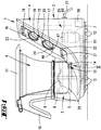
- the kitchen machine 1 shown in Figure 1 has a housing 2, which consists essentially of two Areas composed.
- the first, lower area is a mixing vessel receiving area 3 from which one at an angle of approx. 60 degrees to the horizontal upward extending operator and Electronics area 4 extends.
- the mixing vessel receiving area 3 has a circular shape Recording 5 for a stirring vessel 6. Furthermore is in this area 3 a drive motor 7 coaxial with the recording 5 assigned, via which by means of a drive shaft 8 a arranged in the stirring vessel 6 Agitator 9 can be put into operation.
- the stirring vessel 6 is in the inserted state the handle facing away from the operator and electronics area 4 10 provided. Furthermore, the mixing vessel 6 a lid 11 which, for example, by means of brackets or the like on the stirring vessel 6 is held.
- the provided with feet 12 housing 2 has in Bottom area of the receptacle 5 a temperature sensor 13, which when the mixing vessel is inserted into the receptacle 5 kicks against the bottom of the pot 14.
- the temperature sensor 13 essentially has a covered sensor head 50, which is always in the direction by means of a compression spring 51 on the bottom of the pot 14, i.e. vertically upwards, is burdened.
- Both the one with an electrical connection 52 provided sensor head 50 as well as the compression spring 51 are accommodated in a housing 53, which in Bottom area of the receptacle 5 is fixed (see figure 5).
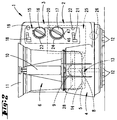
- Operator display 15 In the operator and electronics area 4 is in the Stirring vessel 6 facing surface of the housing wall Operator display 15 provided.
- the latter includes a rotary switch 16 for a temperature preselection, one another rotary switch 17 for preselecting a speed of the Agitator 9, an electronic clock 18 with one for Setting this clock 18 serving rotary switch 19, a button 20 to achieve a turbo switching and an electronic weight display 21 with one of these Display assigned reset button 22.
- the rotary switch 16 and 17 for temperature or speed setting each illuminated by an LED display 23, 24, each display having 23, 24 set points.
- the electrical cable connection to supply the food processor 1 is designated by the number 27.
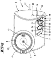
- the lower region of the mixing vessel 6 is in the region of the Recording 5 of the housing 2 can be heated. To do this the food processor 1 in the area of the receptacle 5 electric resistance heater 28 which the lower Area of the mixing bowl 6 encloses.
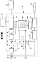
- FIG 6 is a block diagram of the control of the Resistance heater 28 shown.
- the desired temperature is via the rotary switch 16, which as a linear Potentiometer is designed, set and as Voltage value via an analog / digital converter Control circuit 29 supplied as a target value.
- the temperature sensor 13 measures the current temperature at the bottom of the pot 14 and reports after running through a linearization module 30 the determined actual value the control circuit 29. Since the current temperature at the bottom of the vessel is determined then a correction of the determined value in a temperature compensation module 31, in which a Factor, calculated according to the heat transfer numbers becomes. The actual value corrected in this way corresponds thus the actually essential material temperature.
- This actual value becomes the target value in a comparator 32, for example a differential amplifier.
- the heating is controlled depending on the setpoint, with specifications from 40 ° C to 60 ° C with less Controlled energy than with specifications of more than 60 ° C becomes.
- a proportionality module 33 provided in which depending on the specification of the target value Proportionality factors can be selected. Prefers are factors that are specified at 40 ° C up to 60 ° C a value of 1.6 and with specifications of more than 60 ° C corresponds to a value of 2.8.
- This proportionality module 33, a fuse module 34 is connected downstream, which ensures that a temperature of 100 ° C is not exceeded.
- the determined Data about another proportionality module 35 and a filter 36 forwarded to a control module 37.
- a generator acts on this control module 37 38, preferably a sawtooth generator, which in works every 15 seconds.
- Control module 37 a correspondingly lasting for 15 seconds Control window opened, in which one Control of the power consumption of the resistance heating 28 takes place.
- a clock generator 39 is provided for this purpose, which is the data between the second proportionality module 35 and the filter 36 taps and in one Can flow into the control module 37 every second.
- the control module 37 For example, is a high heat output or great energy is required, so within the 15th Second window of the control module 37, for example a 12 second high signal delivered. Over the remaining three seconds correspondingly a low signal. These signals correspond for example the amount of resistance heating 28 applied voltage. However, it is a lower one Energy is required, e.g. within the 15 second window is only 5 seconds long high signal delivered, followed by 10 seconds persistent lower signal. It is also conceivable the resistance heater within the set window 28 completely on or off. The power consumption the resistance heater 28 is thus in regulated a time interval of 15 seconds, where within these 15 seconds periods of high and low signals are provided.
- the regulation of the heating output is still from the Temperature rise rate affected.
- the actual values determined after the temperature compensation module 31 tapped and, after run a filter 40 to a temperature rise rate module 41 forwarded.
- the determined here Values become an intermediate via a coupling point 42 the security module 34 and the second proportionality module 35 arranged comparators 43, for example in the form of a differential amplifier.
- the latter now determines that to the control module 37 value to be derived from the values of the first proportionality module 33 and the coupling point 42.
- a filling quantity determination also influences the Control of heating power.
- a branch is provided for this, which is also the data after the temperature compensation module 31 taps and, after a predetermined time after switching on the agitator 9, for example 2 minutes, this signal on a filling quantity determination module 44 switches.
- the result of The filling quantity is determined in an evaluation unit 45 in Relation to the preset speed of the agitator 9, which is adjustable via the rotary switch 17 is set.
- the ratio is determined in the filling quantity determination module 44 of supplied heating energy to increase the temperature determines what a conclusion on the filling quantity allows. However, since at different speeds of the Agitator 9 different heat transfer resistances there is a correct filling quantity determination required. This takes place in the already mentioned Evaluation unit 45.
- the value thus determined is compared with the Contents of a characteristic field compared.
- the content the characteristic field is based on empirically determined Measured values, which with different fillings with different Temperature rise values and speeds were determined.
- the empirically determined values are saved in a non-volatile memory.
- the corrected resulting from the evaluation unit 45 Filling quantity is given as a value to that already mentioned Coupling point 42 forwarded where a link of these values with the temperature rise rate values he follows.
- the resistance heater 28 is thus controlled in addition to the usual target / actual value comparison by the Determination of the rate of temperature rise and the filling quantity.
- the control is designed so that regardless of the thermal conductivity and the amount of heating Stirred goods in the mixing vessel 6 a more even Heating takes place.
- FIG. 7 there is an example of a temperature rise curve shown.
- Figure 8 shows the line the power consumption at the same time unit as in the temperature characteristic.
- T1 is the preset maximum temperature featured.
- P1 denotes the maximum in FIG Power consumption.
- an agitator setting can be selected, which starts a dough mixer.
- this agitator setting is the rotary switch 17th from a zero position 46 counterclockwise twisted into a dough stirring position 47.
- stirring phases due to regular stoppages interrupted. The latter extend in comparison about three times the stirring phases, preferably a rest period of 4.5 seconds compared to a stirring phase of 1.5 seconds is.
- Advantage of this dough mixer is that the dough to be stirred is in the stirring phases can put again.
- the circuit is like that too advantageous that they are used for engine cooling can. In the stirring phase, therefore, can be short-term realize very high speeds.
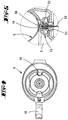
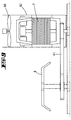
- the rest phases are used for active Cooling of the drive motor 7 by means of one in one Air duct 62 arranged, separate cooling fan 60 (see Fig. 9).
- the drive motor 7 is standing Universal motor (series motor) designed and also positioned in the area of the air duct 62. This drives the agitator 9 via a belt 61.
- the motor is supplied with mains voltage and via a Triac driven.
- the engine is here designed so that when using the device maximum intended load a sufficient rotational movement (Circulation in the production of dough) guaranteed is.
- the external cooling fan 60 generates during the maximum air output in this operating mode, however alone is not enough for the drive motor 7 below the limit prescribed for use to cool down the temperature.
- the duration (pulse width) of the control pulse is sufficiently designed so that for the Use of the device the maximum intended load necessary work is done.
- the ratio of Pulse width of the control pulse for the motor in each case subsequent off time is set so that at maximum air output of the external cooling fan 60 and at the maximum intended load for a particular Duration the prescribed for the use of the device Limit temperature of the motor windings not exceeded becomes.
- the cooling fan shown schematically in FIG. 9 60 is via its own electric motor, not shown driven.
- the Drive motor 7 With a basic or normal load, as with the majority Device applications is used, the Drive motor 7 within its characteristic by phase control regulated to the required speeds. For the necessary cooling is provided by the external cooling fan 60, where the air output of the heat development in the drive motor 7, measured by a temperature sensor, not shown in the drive motor 7, by electronic control is adjusted.
- Both the dough agitator circuit and the turbo circuit can only be activated if the heating temperature preset below a certain limit temperature is.
- a limit temperature is preferred here of 70 ° C. This is due in particular to the fact that already locally at temperatures of more than 70 ° C Boiling phenomena can occur, which are caused by the Stirring function can be strengthened. This can happen at very high Speeds, which both in the dough mixer and can also occur in the turbo circuit cause that a very strong pressure builds up and the Lid of the mixing vessel is lifted off.
- electronics cause that depending on a preset speed of the agitator 9 Start up the agitator 9 to this speed initially slowly and then faster. For this purpose, that at a preset speed of up to about 1000 revolutions per minute always a slow one Start-up takes place. At higher speeds, above about 1000 revolutions per minute a jerky start. However, is the heating temperature set to greater than 70 ° C, so also at a setting of a rotational speed of more than 1,000 rpm a slow start and the speed nevertheless does not exceed 1,000 rpm.
- the Speed change during normal operation i.e. at constant speed of the agitator, without gear. The change in speed is determined by means of a Control over the leading edge angle made.
- High speeds of more than 1,000 rpm are used in the most applications for crushing the pot content set. You need the maximum torque of the drive motor 7 to prevent wedging when starting to avoid the mixing tool in the medium. Of the available drive motor 7 can the maximum Apply torque only at maximum supply voltage, d. H. Start without leading edge and then open regulate the target speed. Low speeds of less than 1,000 rpm are mainly used in cooking used for stirring. Here a crushing of the Pot contents can be avoided in which the drive motor 7 with low supply voltage (maximum leading edge) started and then regulated to the target speed becomes.
- the speed control is via a microprocessor implemented programmatically.
- the setpoint is specified continuously via the rotary switch already mentioned 17, which is designed as a potentiometer.
- the feedback about the actual value a sensor that detects the rotational movements of the drive motor 7 taps on the motor shaft.
- the interpretation of the Components determining the control loop are of such a nature that that a control range of at least 1: 100 is reached is, d. H. Speeds of z. B. 100 to about 10,000 RPM on the mixing tool.
- Said switches 16 and 17 for presetting Temperature and speed are, as already mentioned, means LED displays 23, 24 illuminated. These lights have a signal effect for the user, since at higher Setting values a lighting of a different color and / or Intensity is assigned than at lower ones Setting values. It is particularly provided here that the LED displays 23, 24 are designed in two colors, where a yellow area indicates the lower setting values and a red one is assigned to the higher setting values is. While at the lower setting ranges yellow LEDs are strongly activated, the red ones are only weak, takes place with increasingly higher settings a weakening of the activation of the yellow and an increase in the activation of the red LEDs.
- Light emitting components such as B. feed LED's Light from opposite directions in a light guide on.
- the light guide is designed so that Light emitted perpendicular to the direction of the feed the effect of a light bar.
- the feed components LEDs
- the electrical arranged in the operator display 15 Clock 18 has a rotary switch 19 for preselection a heating time and / or a stirring time.
- the setting the clock 18 is done in the simplest way by due to a high rotational speed of the rotary switch 19 a large unit of time over a certain angle of rotation, for example one minute, and a lower one Speed of rotation of the rotary switch 19 over the same angle of rotation a low time unit, for example a second that is assignable. This means, that via the rotary switch 19 both an adjustment in small as well as large steps is possible without drive through the entire setting range have to.
- the one located at the rear of the housing 2 Collective connector 26 is designed as an interface.
- electrical / electronic and / or mechanical components query loops be brought together.
- functional failures in the main components, like motor 7 and heater 28, or other electrical Elements can be detected.
- Error messages So e.g. also voltage drops in the motor windings or in the electronic elements, with which a targeted troubleshooting is realized.
- EEPROM non-volatile memory
- a part of the calibration circuit can be used for this Query loop of an electrical / electronic component the food processor 1 in a removable and pluggable housing part.
- a housing part in terms of Programmable calibration values and designed as dongle.
- EEPROM non-volatile Memory
- a calibration can be carried out in such a way that the dongle placed on the collector plug 26 or the interface and then the food processor 1 is switched on becomes.
- the time display 18 shows the respective calibration step on, preferably ten steps carried out become.
- the scale display 21 shows in the various Calibration steps to be set Characteristic data, such as when tare the scale one point. After switching on the food processor 1 for The balance display 21 first shows the calibration Version number of the dongle. Is the food processor 1 earlier with an older one Dongle version has been calibrated, the version number flashes in the scale display 21. After completing a The reset button 22 becomes every calibration step to move to the next calibration step reach.
- the collector plug 26 can also serve as an interface for be a computer.
- the over the query loops determined values can thus be from a Computers can be recorded and evaluated.
- Based on this determined and by Computer captured data can also be found in the computer stored target data comparisons are made, according to which the user can use the computer to operate incorrectly, such as set too high Temperature or speed, can be communicated.
- the interface or the common connector 26 to a computer-assisted operation of the To use food processor 1.
- the computer for example after filling predetermined ingredients into the mixing vessel 6 the computer the speed of the agitator 9, the Temperature of the resistance heater 28 and the duration of the Determine, regulate and control stirring or heating.
Landscapes
- Engineering & Computer Science (AREA)
- Food Science & Technology (AREA)
- Physics & Mathematics (AREA)
- General Physics & Mathematics (AREA)
- Automation & Control Theory (AREA)
- Mechanical Engineering (AREA)
- Food-Manufacturing Devices (AREA)
- Mixers Of The Rotary Stirring Type (AREA)
- Manufacturing And Processing Devices For Dough (AREA)
Priority Applications (2)
| Application Number | Priority Date | Filing Date | Title |
|---|---|---|---|
| EP05109332A EP1616514B1 (fr) | 1994-04-28 | 1995-04-28 | Robot ménager comportant un bac à agitation et un mécanisme d'entrainement de l'agitateur du bac |
| EP04013318A EP1472962B1 (fr) | 1994-04-28 | 1995-04-28 | Robot menager comportant un bac a agitation et un mecanisme d'entrainement de l'agitateur du bac |
Applications Claiming Priority (3)
| Application Number | Priority Date | Filing Date | Title |
|---|---|---|---|
| DE4414825A DE4414825A1 (de) | 1994-04-28 | 1994-04-28 | Küchenmaschine mit einem Rührgefäß und einem Antrieb für ein Rührwerk in dem Rührgefäß |
| DE4414825 | 1994-04-28 | ||
| EP95919365A EP0757529B1 (fr) | 1994-04-28 | 1995-04-28 | Robot menager comportant un bac a agitation et un mecanisme d'entrainement de l'agitateur du bac |
Related Parent Applications (2)
| Application Number | Title | Priority Date | Filing Date |
|---|---|---|---|
| EP95919365A Division EP0757529B1 (fr) | 1994-04-28 | 1995-04-28 | Robot menager comportant un bac a agitation et un mecanisme d'entrainement de l'agitateur du bac |
| EP95919365.7 Division | 1995-11-09 |
Related Child Applications (4)
| Application Number | Title | Priority Date | Filing Date |
|---|---|---|---|
| EP05109332A Division EP1616514B1 (fr) | 1994-04-28 | 1995-04-28 | Robot ménager comportant un bac à agitation et un mécanisme d'entrainement de l'agitateur du bac |
| EP04013318A Division EP1472962B1 (fr) | 1994-04-28 | 1995-04-28 | Robot menager comportant un bac a agitation et un mecanisme d'entrainement de l'agitateur du bac |
| EP04013318.3 Division-Into | 2004-06-05 | ||
| EP05109332.6 Division-Into | 2005-10-07 |
Publications (3)
| Publication Number | Publication Date |
|---|---|
| EP0966909A2 true EP0966909A2 (fr) | 1999-12-29 |
| EP0966909A3 EP0966909A3 (fr) | 2000-01-05 |
| EP0966909B1 EP0966909B1 (fr) | 2005-11-30 |
Family
ID=6516655
Family Applications (4)
| Application Number | Title | Priority Date | Filing Date |
|---|---|---|---|
| EP99118360A Expired - Lifetime EP0966909B1 (fr) | 1994-04-28 | 1995-04-28 | Appareil de cuisine avec un bol de mixage et un mécanisme d'entraínement pour un outil de mixage dans le bol |
| EP05109332A Expired - Lifetime EP1616514B1 (fr) | 1994-04-28 | 1995-04-28 | Robot ménager comportant un bac à agitation et un mécanisme d'entrainement de l'agitateur du bac |
| EP95919365A Expired - Lifetime EP0757529B1 (fr) | 1994-04-28 | 1995-04-28 | Robot menager comportant un bac a agitation et un mecanisme d'entrainement de l'agitateur du bac |
| EP04013318A Expired - Lifetime EP1472962B1 (fr) | 1994-04-28 | 1995-04-28 | Robot menager comportant un bac a agitation et un mecanisme d'entrainement de l'agitateur du bac |
Family Applications After (3)
| Application Number | Title | Priority Date | Filing Date |
|---|---|---|---|
| EP05109332A Expired - Lifetime EP1616514B1 (fr) | 1994-04-28 | 1995-04-28 | Robot ménager comportant un bac à agitation et un mécanisme d'entrainement de l'agitateur du bac |
| EP95919365A Expired - Lifetime EP0757529B1 (fr) | 1994-04-28 | 1995-04-28 | Robot menager comportant un bac a agitation et un mecanisme d'entrainement de l'agitateur du bac |
| EP04013318A Expired - Lifetime EP1472962B1 (fr) | 1994-04-28 | 1995-04-28 | Robot menager comportant un bac a agitation et un mecanisme d'entrainement de l'agitateur du bac |
Country Status (9)
| Country | Link |
|---|---|
| EP (4) | EP0966909B1 (fr) |
| AT (4) | ATE329512T1 (fr) |
| AU (1) | AU2523395A (fr) |
| DE (5) | DE4414825A1 (fr) |
| DK (1) | DK0757529T3 (fr) |
| ES (4) | ES2148519T3 (fr) |
| GR (1) | GR3034422T3 (fr) |
| PT (3) | PT757529E (fr) |
| WO (1) | WO1995029614A2 (fr) |
Cited By (10)
| Publication number | Priority date | Publication date | Assignee | Title |
|---|---|---|---|---|
| EP1561409A1 (fr) | 2004-02-05 | 2005-08-10 | Vorwerk & Co. Interholding GmbH | Procédé pour la préparation d'aliments avec un appareil de cuisine et appareil de cuisine |
| EP1647217A1 (fr) * | 2004-10-15 | 2006-04-19 | Bionicum Establishment | Appareil de cuisine à plusieurs usages |
| WO2008055749A1 (fr) * | 2006-11-07 | 2008-05-15 | Robert Bosch Gmbh | Commande pour une balance |
| WO2011107811A1 (fr) * | 2010-03-05 | 2011-09-09 | Ksenija Kralj | Appareil de préparation de nourriture et de desserts à la vapeur |
| CN102359834A (zh) * | 2011-09-06 | 2012-02-22 | 际华三五零二职业装有限公司 | 多点自控恒温检温装置 |
| CN106665725A (zh) * | 2017-02-20 | 2017-05-17 | 刘魁 | 一种揉面效果好的面条机 |
| US10085599B2 (en) | 2014-12-19 | 2018-10-02 | Whirlpool Corporation | Multi-cook and food processing prep product |
| CN110269526A (zh) * | 2018-03-13 | 2019-09-24 | 德国福维克控股公司 | 家用厨房多用机 |
| US10427316B2 (en) | 2010-04-29 | 2019-10-01 | Whirlpool Corporation | Food processor with adjustable blade assembly |
| US10449685B2 (en) | 2010-04-29 | 2019-10-22 | Whirlpool Corporation | Food processor with adjustable blade assembly |
Families Citing this family (36)
| Publication number | Priority date | Publication date | Assignee | Title |
|---|---|---|---|---|
| DE29712528U1 (de) * | 1997-07-15 | 1997-09-18 | DEP Corp., Pembroke Pines, Flo. | Vorrichtung zum Homogenisieren und/oder Erwärmen von flüssigen oder breiförmigen Substanzen in einem mit der Vorrichtung verbindbaren Behälter |
| ES2150855B1 (es) * | 1998-06-10 | 2001-06-16 | Hispainox S A | Batidora trituradora electrica para cocinar, de uso domestico. |
| US7499003B2 (en) * | 2004-03-31 | 2009-03-03 | Electrolux Home Products, Inc. | Disappearing interface system |
| US20060286255A1 (en) * | 2005-06-18 | 2006-12-21 | Zhaoxia Xu | Automated Soup Making Apparatus |
| GB2441508A (en) * | 2006-09-08 | 2008-03-12 | Kenwood Ltd | Stand mixer with heating and thermal sensing means |
| BRPI0702019A2 (pt) * | 2007-05-10 | 2008-12-23 | Whirlpool Sa | dispositivo de sinalizaÇço para equipamento de preparaÇço de alimentos |
| DE102007031372B4 (de) * | 2007-07-05 | 2013-04-11 | It-Designers Gmbh | Küchenmaschine |
| DE102007053876A1 (de) * | 2007-10-18 | 2009-04-23 | Frank Kaltenbach | Vorrichtung zum Zerkleinern von Lebensmitteln |
| DE102007059236A1 (de) | 2007-12-07 | 2009-06-10 | Vorwerk & Co. Interholding Gmbh | Elektromotorisch betriebene Küchenmaschine |
| GB2457722B (en) * | 2008-02-23 | 2012-02-22 | Kenwood Ltd | Improvements in or relating to food mixers and processors |
| DE102008040935A1 (de) | 2008-08-01 | 2010-02-04 | BSH Bosch und Siemens Hausgeräte GmbH | Küchengerät mit Motordrehzahlanzeige |
| DE102009050693A1 (de) * | 2009-10-26 | 2011-04-28 | Ralph Schelle | Drehzahlgeregelter Lüfter |
| EP2345350B1 (fr) * | 2010-01-18 | 2013-10-30 | BSH Bosch und Siemens Hausgeräte GmbH | Appareil de cuisson |
| DE102010000299B4 (de) | 2010-02-04 | 2019-02-21 | Vorwerk & Co. Interholding Gmbh | Küchenmaschine |
| DE102010016024B4 (de) * | 2010-03-19 | 2018-02-22 | Vorwerk & Co. Interholding Gmbh | Küchenmaschine |
| EP2388564A1 (fr) | 2010-05-20 | 2011-11-23 | Koninklijke Philips Electronics N.V. | Estimation de la température |
| DE102010017335A1 (de) * | 2010-06-11 | 2011-12-15 | Vorwerk & Co. Interholding Gmbh | Küchenmaschine mit einem Rührgefäß sowie Verfahren zum Betreiben einer solchen Küchenmaschine |
| DE102010037769B4 (de) * | 2010-09-24 | 2019-09-19 | Vorwerk & Co. Interholding Gmbh | Elektrisch betriebene Küchenmaschine sowie Verfahren zum Betreiben einer solchen Küchenmaschine |
| DE102012103882A1 (de) * | 2011-05-11 | 2012-11-15 | Vorwerk & Co. Interholding Gmbh | Verfahren zum Zubereiten von Speisen in einem Gargefäß sowie elektrische Küchenmaschine mit einem Gargefäß |
| EP2564735A1 (fr) | 2011-08-31 | 2013-03-06 | Koninklijke Philips Electronics N.V. | Chauffage |
| DE102012103877A1 (de) | 2012-05-03 | 2013-11-07 | Vorwerk & Co. Interholding Gmbh | Deckel für ein Gargefäß sowie Gargefäß mit einem Deckel |
| DE202012105011U1 (de) | 2012-12-21 | 2013-01-25 | Vorwerk & Co. Interholding Gmbh | Elektromotorisch betriebene Küchenmaschine |
| US10413109B2 (en) | 2013-03-13 | 2019-09-17 | Spectrum Brands, Inc. | Food preparation appliance for steam cooking and food processing |
| DE102014115346A1 (de) | 2014-10-21 | 2016-05-04 | Vorwerk & Co. Interholding Gmbh | Verfahren und Küchenmaschine zum Zubereiten eines Zubereitungsguts |
| DE102015103596A1 (de) * | 2015-03-11 | 2016-09-15 | Vorwerk & Co. Interholding Gmbh | Verfahren zum Betrieb einer elektromotorisch angetriebenen Küchenmaschine |
| ES2807562T3 (es) * | 2015-09-18 | 2021-02-23 | Vorwerk Co Interholding | Sistema y método para mejorar la reproducibilidad de los resultados de la cocción de un aparato de cocina multifuncional |
| EP3189733B1 (fr) | 2016-01-07 | 2020-09-30 | Taurus Research and Development, SLU | Procédé pour le traitement de pâte et émulsions alimentaires |
| DE202016102933U1 (de) | 2016-06-01 | 2017-09-04 | Kompernaß Handelsgesellschaft mbH | Küchenmaschine |
| USD853782S1 (en) | 2017-02-20 | 2019-07-16 | Whirlpool Corporation | Food processor |
| US10966506B2 (en) | 2018-10-30 | 2021-04-06 | Rea Innovations, Inc. | Dual-piston appliance for processing of cosmetic formulations |
| CA3142059A1 (fr) | 2019-05-28 | 2020-12-03 | Sharkninja Operating Llc | Robot de cuisine chauffant |
| US11660578B2 (en) | 2019-10-15 | 2023-05-30 | Rea Innovations, Inc. | Systems and methods for blending solid-shell cosmetic ingredient capsules and blendable cosmetic ingredient capsules |
| US11497692B2 (en) | 2019-10-15 | 2022-11-15 | Rea Innovations, Inc. | Systems and methods for blending solid-shell cosmetic ingredient capsules and blendable cosmetic ingredient capsules |
| USD986498S1 (en) | 2020-03-04 | 2023-05-16 | Rea Innovations, Inc. | Cosmetic appliance |
| CN112386094B (zh) * | 2020-12-01 | 2022-06-28 | 珠海优特智厨科技有限公司 | 一种烹饪器具的控制方法以及烹饪系统 |
| US11918142B2 (en) * | 2021-04-02 | 2024-03-05 | Ascent Technology, LLC | Artificial gravity heating device |
Citations (2)
| Publication number | Priority date | Publication date | Assignee | Title |
|---|---|---|---|---|
| DE3507276A1 (de) | 1985-03-01 | 1986-09-18 | Vorwerk & Co Interholding Gmbh, 5600 Wuppertal | Elektromotorisch betriebenes haushaltsmixgeraet |
| EP0513483A1 (fr) | 1991-05-11 | 1992-11-19 | Braun Aktiengesellschaft | Robot de cuisine électrique |
Family Cites Families (8)
| Publication number | Priority date | Publication date | Assignee | Title |
|---|---|---|---|---|
| US4323110A (en) * | 1977-01-11 | 1982-04-06 | Anchor Hocking Corporation | Food preparation process |
| GB1544035A (en) * | 1978-03-20 | 1979-04-11 | Diamond H Controls Ltd | Means for presetting and adjusting the hours and minute settings on electronically controlled timing mechanisms |
| DE3430993A1 (de) * | 1984-08-23 | 1986-03-06 | Miele & Cie GmbH & Co, 4830 Gütersloh | Optische schaltstufenanzeige fuer drehwahlschalter von haushaltsgeraeten, insbesondere von herden |
| JPH0523180Y2 (fr) * | 1989-01-13 | 1993-06-14 | ||
| US5274216A (en) * | 1989-08-15 | 1993-12-28 | Aladdin Synergetics, Inc. | Food rethermalizing and satelliting tray |
| JPH04148635A (ja) * | 1990-10-11 | 1992-05-21 | Taisho Denki Hanbai Kk | パン生地こね方法 |
| JPH04244521A (ja) * | 1991-01-29 | 1992-09-01 | Toshiba Corp | 加熱調理器 |
| JP2848015B2 (ja) * | 1991-05-17 | 1999-01-20 | 松下電器産業株式会社 | 調理器 |
-
1994
- 1994-04-28 DE DE4414825A patent/DE4414825A1/de not_active Ceased
-
1995
- 1995-04-28 AT AT04013318T patent/ATE329512T1/de not_active IP Right Cessation
- 1995-04-28 ES ES95919365T patent/ES2148519T3/es not_active Expired - Lifetime
- 1995-04-28 PT PT95919365T patent/PT757529E/pt unknown
- 1995-04-28 PT PT05109332T patent/PT1616514E/pt unknown
- 1995-04-28 EP EP99118360A patent/EP0966909B1/fr not_active Expired - Lifetime
- 1995-04-28 DE DE59508516T patent/DE59508516D1/de not_active Expired - Lifetime
- 1995-04-28 AT AT05109332T patent/ATE374553T1/de not_active IP Right Cessation
- 1995-04-28 PT PT04013318T patent/PT1472962E/pt unknown
- 1995-04-28 DK DK95919365T patent/DK0757529T3/da active
- 1995-04-28 DE DE59511052T patent/DE59511052D1/de not_active Expired - Fee Related
- 1995-04-28 WO PCT/EP1995/001637 patent/WO1995029614A2/fr not_active Ceased
- 1995-04-28 AT AT99118360T patent/ATE311137T1/de not_active IP Right Cessation
- 1995-04-28 ES ES99118360T patent/ES2252900T3/es not_active Expired - Lifetime
- 1995-04-28 EP EP05109332A patent/EP1616514B1/fr not_active Expired - Lifetime
- 1995-04-28 DE DE59511026T patent/DE59511026D1/de not_active Expired - Lifetime
- 1995-04-28 EP EP95919365A patent/EP0757529B1/fr not_active Expired - Lifetime
- 1995-04-28 ES ES05109332T patent/ES2290856T3/es not_active Expired - Lifetime
- 1995-04-28 ES ES04013318T patent/ES2262067T3/es not_active Expired - Lifetime
- 1995-04-28 AU AU25233/95A patent/AU2523395A/en not_active Abandoned
- 1995-04-28 AT AT95919365T patent/ATE194056T1/de not_active IP Right Cessation
- 1995-04-28 EP EP04013318A patent/EP1472962B1/fr not_active Expired - Lifetime
- 1995-04-28 DE DE59511084T patent/DE59511084D1/de not_active Expired - Fee Related
-
2000
- 2000-09-18 GR GR20000402110T patent/GR3034422T3/el not_active IP Right Cessation
Patent Citations (2)
| Publication number | Priority date | Publication date | Assignee | Title |
|---|---|---|---|---|
| DE3507276A1 (de) | 1985-03-01 | 1986-09-18 | Vorwerk & Co Interholding Gmbh, 5600 Wuppertal | Elektromotorisch betriebenes haushaltsmixgeraet |
| EP0513483A1 (fr) | 1991-05-11 | 1992-11-19 | Braun Aktiengesellschaft | Robot de cuisine électrique |
Cited By (13)
| Publication number | Priority date | Publication date | Assignee | Title |
|---|---|---|---|---|
| EP1561409A1 (fr) | 2004-02-05 | 2005-08-10 | Vorwerk & Co. Interholding GmbH | Procédé pour la préparation d'aliments avec un appareil de cuisine et appareil de cuisine |
| EP1647217A1 (fr) * | 2004-10-15 | 2006-04-19 | Bionicum Establishment | Appareil de cuisine à plusieurs usages |
| WO2008055749A1 (fr) * | 2006-11-07 | 2008-05-15 | Robert Bosch Gmbh | Commande pour une balance |
| WO2011107811A1 (fr) * | 2010-03-05 | 2011-09-09 | Ksenija Kralj | Appareil de préparation de nourriture et de desserts à la vapeur |
| US10427316B2 (en) | 2010-04-29 | 2019-10-01 | Whirlpool Corporation | Food processor with adjustable blade assembly |
| US10449685B2 (en) | 2010-04-29 | 2019-10-22 | Whirlpool Corporation | Food processor with adjustable blade assembly |
| CN102359834B (zh) * | 2011-09-06 | 2014-06-25 | 际华三五零二职业装有限公司 | 多点自控恒温检温装置 |
| CN102359834A (zh) * | 2011-09-06 | 2012-02-22 | 际华三五零二职业装有限公司 | 多点自控恒温检温装置 |
| US10085599B2 (en) | 2014-12-19 | 2018-10-02 | Whirlpool Corporation | Multi-cook and food processing prep product |
| US10993583B2 (en) | 2014-12-19 | 2021-05-04 | Whirlpool Corporation | Multi-cook and food processing prep product |
| US12016498B2 (en) | 2014-12-19 | 2024-06-25 | Whirlpool Corporation | Multi-cook and food processing prep product |
| CN106665725A (zh) * | 2017-02-20 | 2017-05-17 | 刘魁 | 一种揉面效果好的面条机 |
| CN110269526A (zh) * | 2018-03-13 | 2019-09-24 | 德国福维克控股公司 | 家用厨房多用机 |
Also Published As
| Publication number | Publication date |
|---|---|
| EP1472962B1 (fr) | 2006-06-14 |
| ATE311137T1 (de) | 2005-12-15 |
| PT1472962E (pt) | 2006-08-31 |
| ES2148519T3 (es) | 2000-10-16 |
| ATE194056T1 (de) | 2000-07-15 |
| GR3034422T3 (en) | 2000-12-29 |
| ATE329512T1 (de) | 2006-07-15 |
| DE59511026D1 (de) | 2006-01-05 |
| EP0757529A1 (fr) | 1997-02-12 |
| PT1616514E (pt) | 2007-11-15 |
| DE59508516D1 (de) | 2000-08-03 |
| PT757529E (pt) | 2000-10-31 |
| EP0966909A3 (fr) | 2000-01-05 |
| ES2290856T3 (es) | 2008-02-16 |
| WO1995029614A3 (fr) | 1995-11-30 |
| EP1616514B1 (fr) | 2007-10-03 |
| EP0966909B1 (fr) | 2005-11-30 |
| DK0757529T3 (da) | 2000-11-06 |
| DE59511084D1 (de) | 2007-11-15 |
| ATE374553T1 (de) | 2007-10-15 |
| ES2252900T3 (es) | 2006-05-16 |
| AU2523395A (en) | 1995-11-29 |
| DE59511052D1 (de) | 2006-07-27 |
| EP1616514A1 (fr) | 2006-01-18 |
| WO1995029614A2 (fr) | 1995-11-09 |
| EP1472962A1 (fr) | 2004-11-03 |
| EP0757529B1 (fr) | 2000-06-28 |
| DE4414825A1 (de) | 1995-11-02 |
| ES2262067T3 (es) | 2006-11-16 |
Similar Documents
| Publication | Publication Date | Title |
|---|---|---|
| EP0757529B1 (fr) | Robot menager comportant un bac a agitation et un mecanisme d'entrainement de l'agitateur du bac | |
| EP2460452B1 (fr) | Machine de cuisine dotée d'un récipient mélangeur | |
| EP2874526B1 (fr) | Machine pour la cuisine | |
| DE69704454T2 (de) | Küchengerät | |
| DE102010037769B4 (de) | Elektrisch betriebene Küchenmaschine sowie Verfahren zum Betreiben einer solchen Küchenmaschine | |
| DE3650352T2 (de) | Vorrichtung zur Herstellung von Brot. | |
| DE4139804C1 (fr) | ||
| DE3879368T3 (de) | Reglervorrichtung für einen Ofen. | |
| DE3485991T2 (de) | Knetvorrichtung fuer eine vorrichtung zum backen von brot. | |
| EP4026460B1 (fr) | Appareil de préparation des aliments permettant de couper les aliments, pièce rapportée de broyage et procédé | |
| DE3112174A1 (de) | Kuechenmaschine | |
| DE102015216678B4 (de) | Handgehaltenes elektrisch angetriebenes Haushaltsgerät mit Modiauswahl | |
| DE60214214T2 (de) | Vorrichtung und verfahren zum kochen von nahrungsmitteln mit mikrowellen | |
| DE2117010A1 (de) | Handrührgerät | |
| EP0573759B1 (fr) | ContrÔl de l'alimentation d'un hachoir de viande | |
| EP4494536B1 (fr) | Appareil de préparation d'aliments pour couper des aliments, accessoire de broyage et procédé | |
| DE3942712A1 (de) | Elektrisches handruehrgeraet | |
| AT503495B1 (de) | Vorrichtung zum zubereiten von getränken | |
| CH664480A5 (de) | Mobiler mixer mit stufenloser drehzahlregulierung und zuschaltbarer heizung. | |
| DE69700921T2 (de) | Kochgerät mit mehreren Kochleistungen | |
| DE102012220996A1 (de) | Küchengerät | |
| DE102023003998A1 (de) | Softwaregesteuertes Verfahren zur Konditionierung von Material wie schmelzbare Lebensmittel | |
| DE1007482B (de) | Elektromotorischer Antriebssockel fuer aufsetzbare Haushaltkuechengeraete | |
| WO2017037159A1 (fr) | Appareil électroménager portatif à vitesse sélectionnable | |
| DE8713921U1 (de) | Vorrichtung zum Portionieren und/oder Zerkleinern von teigförmigem Lebensmittelgut |
Legal Events
| Date | Code | Title | Description |
|---|---|---|---|
| PUAI | Public reference made under article 153(3) epc to a published international application that has entered the european phase |
Free format text: ORIGINAL CODE: 0009012 |
|
| PUAL | Search report despatched |
Free format text: ORIGINAL CODE: 0009013 |
|
| AC | Divisional application: reference to earlier application |
Ref document number: 757529 Country of ref document: EP |
|
| AK | Designated contracting states |
Kind code of ref document: A2 Designated state(s): AT BE CH DE DK ES FR GB GR IE IT LI LU MC NL PT SE |
|
| AX | Request for extension of the european patent |
Free format text: LT PAYMENT 19991007;SI PAYMENT 19991007 |
|
| AK | Designated contracting states |
Kind code of ref document: A3 Designated state(s): AT BE CH DE DK ES FR GB GR IE IT LI LU MC NL PT SE |
|
| AX | Request for extension of the european patent |
Free format text: LT PAYMENT 19991007;SI PAYMENT 19991007 |
|
| RTI1 | Title (correction) |
Free format text: FOOD PROCESSOR WITH A MIXING VESSEL AND A DRIVE MECHANISM FOR AN AGITATOR IN THE MIXING VESSEL |
|
| RTI1 | Title (correction) |
Free format text: FOOD PROCESSOR WITH A MIXING VESSEL AND A DRIVE MECHANISM FOR AN AGITATOR IN THE MIXING VESSEL |
|
| 17P | Request for examination filed |
Effective date: 20000630 |
|
| AKX | Designation fees paid |
Free format text: AT BE CH DE DK ES FR GB GR IE IT LI LU MC NL PT SE |
|
| AXX | Extension fees paid |
Free format text: LT PAYMENT 19991007;SI PAYMENT 19991007 |
|
| 17Q | First examination report despatched |
Effective date: 20031217 |
|
| GRAP | Despatch of communication of intention to grant a patent |
Free format text: ORIGINAL CODE: EPIDOSNIGR1 |
|
| GRAS | Grant fee paid |
Free format text: ORIGINAL CODE: EPIDOSNIGR3 |
|
| GRAA | (expected) grant |
Free format text: ORIGINAL CODE: 0009210 |
|
| AC | Divisional application: reference to earlier application |
Ref document number: 0757529 Country of ref document: EP Kind code of ref document: P |
|
| AK | Designated contracting states |
Kind code of ref document: B1 Designated state(s): AT BE CH DE DK ES FR GB GR IE IT LI LU MC NL PT SE |
|
| AX | Request for extension of the european patent |
Extension state: LT SI |
|
| PG25 | Lapsed in a contracting state [announced via postgrant information from national office to epo] |
Ref country code: NL Free format text: LAPSE BECAUSE OF FAILURE TO SUBMIT A TRANSLATION OF THE DESCRIPTION OR TO PAY THE FEE WITHIN THE PRESCRIBED TIME-LIMIT Effective date: 20051130 Ref country code: IE Free format text: LAPSE BECAUSE OF FAILURE TO SUBMIT A TRANSLATION OF THE DESCRIPTION OR TO PAY THE FEE WITHIN THE PRESCRIBED TIME-LIMIT Effective date: 20051130 Ref country code: GB Free format text: LAPSE BECAUSE OF FAILURE TO SUBMIT A TRANSLATION OF THE DESCRIPTION OR TO PAY THE FEE WITHIN THE PRESCRIBED TIME-LIMIT Effective date: 20051130 |
|
| REG | Reference to a national code |
Ref country code: GB Ref legal event code: FG4D Free format text: NOT ENGLISH Ref country code: CH Ref legal event code: EP |
|
| REG | Reference to a national code |
Ref country code: IE Ref legal event code: FG4D Free format text: LANGUAGE OF EP DOCUMENT: GERMAN |
|
| REF | Corresponds to: |
Ref document number: 59511026 Country of ref document: DE Date of ref document: 20060105 Kind code of ref document: P |
|
| PG25 | Lapsed in a contracting state [announced via postgrant information from national office to epo] |
Ref country code: SE Free format text: LAPSE BECAUSE OF FAILURE TO SUBMIT A TRANSLATION OF THE DESCRIPTION OR TO PAY THE FEE WITHIN THE PRESCRIBED TIME-LIMIT Effective date: 20060228 Ref country code: DK Free format text: LAPSE BECAUSE OF FAILURE TO SUBMIT A TRANSLATION OF THE DESCRIPTION OR TO PAY THE FEE WITHIN THE PRESCRIBED TIME-LIMIT Effective date: 20060228 |
|
| PG25 | Lapsed in a contracting state [announced via postgrant information from national office to epo] |
Ref country code: MC Free format text: LAPSE BECAUSE OF NON-PAYMENT OF DUE FEES Effective date: 20060430 Ref country code: LI Free format text: LAPSE BECAUSE OF NON-PAYMENT OF DUE FEES Effective date: 20060430 Ref country code: CH Free format text: LAPSE BECAUSE OF NON-PAYMENT OF DUE FEES Effective date: 20060430 Ref country code: BE Free format text: LAPSE BECAUSE OF NON-PAYMENT OF DUE FEES Effective date: 20060430 |
|
| REG | Reference to a national code |
Ref country code: GR Ref legal event code: EP Ref document number: 20060400524 Country of ref document: GR |
|
| REG | Reference to a national code |
Ref country code: ES Ref legal event code: FG2A Ref document number: 2252900 Country of ref document: ES Kind code of ref document: T3 |
|
| LTIE | Lt: invalidation of european patent or patent extension |
Effective date: 20051130 |
|
| NLV1 | Nl: lapsed or annulled due to failure to fulfill the requirements of art. 29p and 29m of the patents act | ||
| GBV | Gb: ep patent (uk) treated as always having been void in accordance with gb section 77(7)/1977 [no translation filed] |
Effective date: 20051130 |
|
| ET | Fr: translation filed | ||
| REG | Reference to a national code |
Ref country code: IE Ref legal event code: FD4D |
|
| PLBE | No opposition filed within time limit |
Free format text: ORIGINAL CODE: 0009261 |
|
| STAA | Information on the status of an ep patent application or granted ep patent |
Free format text: STATUS: NO OPPOSITION FILED WITHIN TIME LIMIT |
|
| 26N | No opposition filed |
Effective date: 20060831 |
|
| REG | Reference to a national code |
Ref country code: CH Ref legal event code: PL |
|
| PGFP | Annual fee paid to national office [announced via postgrant information from national office to epo] |
Ref country code: AT Payment date: 20070406 Year of fee payment: 13 |
|
| BERE | Be: lapsed |
Owner name: VORWERK & CO. INTERHOLDING G.M.B.H. Effective date: 20060430 |
|
| PGFP | Annual fee paid to national office [announced via postgrant information from national office to epo] |
Ref country code: GR Payment date: 20070315 Year of fee payment: 13 |
|
| PG25 | Lapsed in a contracting state [announced via postgrant information from national office to epo] |
Ref country code: LU Free format text: LAPSE BECAUSE OF NON-PAYMENT OF DUE FEES Effective date: 20060428 |
|
| PG25 | Lapsed in a contracting state [announced via postgrant information from national office to epo] |
Ref country code: AT Free format text: LAPSE BECAUSE OF NON-PAYMENT OF DUE FEES Effective date: 20080428 |
|
| PG25 | Lapsed in a contracting state [announced via postgrant information from national office to epo] |
Ref country code: GR Free format text: LAPSE BECAUSE OF NON-PAYMENT OF DUE FEES Effective date: 20081104 |
|
| PGFP | Annual fee paid to national office [announced via postgrant information from national office to epo] |
Ref country code: PT Payment date: 20140319 Year of fee payment: 20 |
|
| PGFP | Annual fee paid to national office [announced via postgrant information from national office to epo] |
Ref country code: IT Payment date: 20140423 Year of fee payment: 20 Ref country code: FR Payment date: 20140408 Year of fee payment: 20 Ref country code: DE Payment date: 20140409 Year of fee payment: 20 Ref country code: ES Payment date: 20140410 Year of fee payment: 20 |
|
| REG | Reference to a national code |
Ref country code: DE Ref legal event code: R071 Ref document number: 59511026 Country of ref document: DE |
|
| REG | Reference to a national code |
Ref country code: PT Ref legal event code: MM4A Free format text: MAXIMUM VALIDITY LIMIT REACHED Effective date: 20150428 |
|
| REG | Reference to a national code |
Ref country code: ES Ref legal event code: FD2A Effective date: 20150703 |
|
| PG25 | Lapsed in a contracting state [announced via postgrant information from national office to epo] |
Ref country code: ES Free format text: LAPSE BECAUSE OF EXPIRATION OF PROTECTION Effective date: 20150429 Ref country code: PT Free format text: LAPSE BECAUSE OF EXPIRATION OF PROTECTION Effective date: 20150506 |