EP0966997A2 - Antriebsvorrichtung für eine Schaukel - Google Patents
Antriebsvorrichtung für eine Schaukel Download PDFInfo
- Publication number
- EP0966997A2 EP0966997A2 EP99304733A EP99304733A EP0966997A2 EP 0966997 A2 EP0966997 A2 EP 0966997A2 EP 99304733 A EP99304733 A EP 99304733A EP 99304733 A EP99304733 A EP 99304733A EP 0966997 A2 EP0966997 A2 EP 0966997A2
- Authority
- EP
- European Patent Office
- Prior art keywords
- axle
- torsion spring
- disposed
- drive mechanism
- spring member
- Prior art date
- Legal status (The legal status is an assumption and is not a legal conclusion. Google has not performed a legal analysis and makes no representation as to the accuracy of the status listed.)
- Granted
Links
- 230000007246 mechanism Effects 0.000 title claims abstract description 171
- 210000000078 claw Anatomy 0.000 claims description 14
- 230000014759 maintenance of location Effects 0.000 claims description 12
- 238000003780 insertion Methods 0.000 description 5
- 230000037431 insertion Effects 0.000 description 5
- 238000000034 method Methods 0.000 description 5
- 230000008878 coupling Effects 0.000 description 2
- 238000010168 coupling process Methods 0.000 description 2
- 238000005859 coupling reaction Methods 0.000 description 2
- 230000001419 dependent effect Effects 0.000 description 2
- 230000000717 retained effect Effects 0.000 description 2
- 238000004519 manufacturing process Methods 0.000 description 1
- 210000001364 upper extremity Anatomy 0.000 description 1
Images




Classifications
-
- A—HUMAN NECESSITIES
- A47—FURNITURE; DOMESTIC ARTICLES OR APPLIANCES; COFFEE MILLS; SPICE MILLS; SUCTION CLEANERS IN GENERAL
- A47D—FURNITURE SPECIALLY ADAPTED FOR CHILDREN
- A47D13/00—Other nursery furniture
- A47D13/10—Rocking-chairs; Indoor Swings ; Baby bouncers
- A47D13/105—Rocking-chairs; Indoor Swings ; Baby bouncers pivotally mounted in a frame
Definitions
- this invention relates to swings. More particularly, this invention relates to a drive mechanism for use in an infant's or child's swing.
- swings include a support frame, a hanger pivotally attached to the support frame, and a seat attached to the hanger.
- Such devices are designed to swing the seat in a pendulum motion.
- additional energy must be supplied to this system in order to maintain an approximately constant amplitude over time.
- manually powered or electrically powered drive mechanisms are utilized to supply the energy which is lost.
- the device to Mitchell et al. is a swing assembly which includes a swing drive mechanism (10).
- the swing drive mechanism (10) has a drive sleeve (12) rotatably mounted to an axle (14) that operatively supports the hanger, not shown.
- a drive flange (16) is mounted on the axle (14) with a drive flange coupling device (18) positioned between the drive sleeve (12) and the drive flange (16) to provide a limited lost motion connection.
- the drive flange coupling device (18) includes a hub member (20) coaxially and rotatably mounted on the axle (14) and at least one torsion spring, shown as a pair of torsion springs (24a, 24b), mounted coaxially on the hub member (20).
- a crank, not shown, driven by a motor, not shown, is commonly linked to the drive sleeve (12) through a channel (26) to oscillate the drive sleeve (12) .
- the swing drive mechanism to Mitchell et al. has at a minimum a total of six parts: the drive sleeve (12), the pair of torsion springs 24(a) and 24(b), the hub member (20), the drive flange (16), and the axle (14).
- the swing drive mechanism (10) requires additional mechanisms to couple the swing drive mechanism (10) with the hub, not shown.
- other mechanisms are needed to secure the drive sleeve (12), the torsion springs (24a, 24b), the hub member (20), and the drive flange (16) on axle (14).
- It is still a further object of this invention is to provide the swing drive mechanism with features that reduce undesirable wear and friction.
- the present invention provides a swing drive mechanism for use in an infant's or child's swing.
- Swings commonly include a support frame having at least one hanger pivotally connected to the support frame. Often the hanger is in turn attached to a seat. The seat is thus permitted to oscillate along an arcute path approximating pendulurn motion.
- the energy required to start and maintain the pendulum motion of the swing is commonly supplied by manual energy, such as a wound coil spring which is wound by the user, or by electrical energy, which operates an electrical motor.
- manual energy such as a wound coil spring which is wound by the user
- electrical energy which operates an electrical motor.
- the swing drive mechanism of the present invention generally includes an input mechanism, a torsion spring member connected to the input mechanism, and an output mechanism associated with the input mechanism and interacting with the torsion spring member.
- the torsion spring member of this invention includes a first portion having a length.
- the torsion member has a second portion parallelly disposed and distanced apart relative to the first portion.
- the second portion also has a length.
- the first portion and the second portion are approximately equal in length.
- the output mechanism of this invention includes an axle and a drive flange attached to the axle.
- the axle also includes a mechanism for reducing friction between the output mechanism and the torsion spring member disposed on the drive flange.
- the swing drive mechanism of this invention includes an input mechanism.
- the input mechanism includes a spring securement mechanism.
- the input mechanism includes an axle engagement member disposed proximate to the spring securement mechanism.
- the input mechanism includes a crank engagement mechanism proximate the axle engagement mechanism.
- the spring securement mechanism, the axle engagement mechanism, and the crank engagement mechanism are integrally formed together. However, one skilled in the art can appreciate that the various novel aspects of this invention may be achieved without integrally forming these members together.
- the worker assembling the above disclosed invention is provided with an uncomplicated assembly process.
- the user may secure the torsion spring member with the spring securement mechanism on the input mechanism.
- the worker will associate the input mechanism with the output mechanism.
- the input mechanism is retained with the output mechanism by the axle engagement mechanism.
- the input mechanism is operatively connected with the crank by the crank engagement mechanism.
- the swing drive mechanism of the present invention substantially reduces the number of separate parts necessary for assembly.
- the swing drive mechanism includes an input mechanism, and output mechanism and a torsion spring member. Accordingly, the present invention has substantially reduced the number of separate parts utilized in manufacturing the swing drive mechanism.
- the swing drive mechanism includes a mechanism to reduce friction which occurs between the torsion spring member and the output member within the swing drive mechanism. Accordingly, the amount of energy which needs to be supplied to the swing drive mechanism is reduced. Also, the opportunity for failure due to wear is similarly reduced.
- the swing drive mechanism of this invention minimizes the amount of space occupied by the swing drive mechanism.
- the torsion spring member has a first portion and an second portion which are approximately equal in length. Since, the spring gradient achievable for a torsion spring member is dependent upon the length of the torsion spring member, having a spring which has a first member and a second member which both operate as a spring approximately reduces the necessary length of the torsion spring member in half while maintaining an approximately similar spring gradient as a single linear torsion spring having a length twice as long.
- a swing (112) commonly includes a support frame (114) having at least one hanger (116a, 116b) pivotally connected to the support frame (114).
- the hanger (116a, 116b) is in turn attached to a seat (118).
- the support frame (114) includes a pair of leg connectors (120a, 120b).
- the support frame includes a pair of front legs (122a, 122b) and a pair of rear legs (124a, 124b) attached to the leg connectors (120a, 120b).
- the leg connectors (120a, 120b) provide support for the corresponding hubs (126a, 126b) which provide a pivot point around which the pendulum motion of the seat (118) occurs.
- the swing drive mechanism (110) is shown in Figure 2 as being associated with leg connector (120b). However, one skilled in the art can appreciate that the unique aspects of this invention could instead be associated with the leg connector (120a) without departing from the novel aspects of this invention.
- Figure 2 shows a swing (112) which is commonly known in the trade as an open top swing. This title being derived from the fact that the swing (112) does not include a cross member interconnecting the leg connectors (120a, 120b). It has been found that it is desirable to have a swing (112) which does not have a cross-member thereby increasing the amount of access the operator has to an occupant contained within the seat (118).
- the seat (118) is permitted to oscillate along an arcute path approximating pendulum motion.
- the energy required to start and maintain the pendulum motion of the swing (112) is commonly supplied by manual energy, such as a wound coil spring which is wound by the user, or by electrical energy which operates an electrical motor.
- manual energy such as a wound coil spring which is wound by the user, or by electrical energy which operates an electrical motor.
- electrical energy which operates an electrical motor.
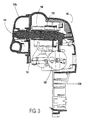
- the swing drive mechanism (110) of the present invention generally includes a motor (128) which powers a crank arm (130).
- the crank arm (130) is associated with an input mechanism (132) which translates the rotational motion of the crank arm (130) into an arcuately oscillating motion.
- the swing drive mechanism (110) further includes an output mechanism (134) associated with the input mechanism (132).
- a torsion spring member (136) is connected to the input mechanism (132).
- the torsion spring member (136) of the present invention includes a first portion (138) which has a length and a second portion (140) which also has a length.
- the second portion (140) is parallelly disposed and distanced apart relative to the first portion (138).
- the torsion spring member (136) includes a lever portion (148) which is approximately perpendicularly disposed relative to and connected with the first portion (138).
- the length of the first portion (138) is approximately equal to the length of the second portion (140).
- the lengths of the first portion (138) and second portion (140) may be varied as required for a particular application.
- the torsion spring member (136) further includes a radiused portion (142) connecting the first portion (138) to the second portion (140).
- a radiused portion (142) connecting the first portion (138) to the second portion (140).
- portions which have various other shapes may also be used to interconnect the first portion (138) to the second portion (140) without departing from the teachings of this invention.
- the first portion (138) and the second portion (140) are each substantially elongate and linear in shape.
- the torsion spring member (136) further includes a third portion (144) connected to the second portion (140) and approximately perpendicularly disposed relative to the first portion (138) and the lever portion (148).
- the torsion spring member (136) includes a hook portion (146) connected to the third portion (144).
- the hook portion (146) is substantially U-shaped.
- the hook portion (146), the third portion (144), the second portion (140), the radiused portion (142), the first portion (138), and the lever portion (148) are integrally formed together.
- the first portion (138), the radiuses portion (142) and the second portion (140) are substantially coplanar.
- the second portion (140), the third portion (144), and the hook portion (146) are coplanar.
- the torsion spring member (136) of this invention is constructed from drawn wire having a circular cross-section.
- various other materials and various other cross-sections may be utilized without departing from the novel aspects of this invention.
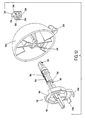
- the output mechanism (134) of the present invention includes an axle (150) and a drive flange (152) attached to the axle (150).
- the drive flange (152) includes a friction reducing mechanism.
- the axle (150) includes a first claw, not shown, connected to the axle (150) and a second claw (156) also connected to the axle (150).
- the axle (150) also includes a retention ring (158) providing a retention ring surface (160) circumferentially disposed around the axle (150).
- the drive flange (152) includes a face (162) having a cavity (164).
- the drive flange (152) also includes a first surface (166) and a second surface (168) disposed on the face (162).
- a first wall (170) and a second wall (172) are disposed proximate the first surface (166) and a second surface (168), respectively.
- the friction reducing mechanism includes a first radiused edge (174) and a second radiused edge (176). The first radiused edge (174) extending from the first surface (166) and the second radiused edge (176) extending from the second surface (168).
- the first surface (166) and the second surface (168) are approximately parallel relative to one another while the first wall (170) and the second wall (172) are approximately skewed, or angularly disposed, relative to one another.
- the output mechanism (134) includes a radial extension (214) extending radially outward away from the face (162). Attached to the radial extension (214) is a pair of abutments (216a, 216b).
- the input mechanism (132) of the present invention includes a spring securement mechanism, an axle engagement mechanism proximate the spring securement mechanism and a crank engagement mechanism proximate the axle engagement mechanism.
- the spring securement mechanism includes a first body (182) having a chamber (184) through the first body (182).
- the chamber (184) terminating at an inner wall (196) having a slot (186) therethrough.
- the first body (182) further including a first rib (188) and a second rib (190) disposed within the chamber (184).
- the first rib (188) and the second rib (190) being parallelly disposed relative to one another and aligned with the slot (186).
- the first body (182) includes an opening (192) through the first body (182) and a ledge (194) extending within the opening (192).
- the first rib (188) and the second rib (190) are space approximately the same distance apart as the width of the slot (186).
- the height of the slot (186) is approximately equal to the distance between the first portion (138) and the second portion (140) of the torsion spring member (136).
- the first body (182) includes roof (202) disposed above the first rib (188) and the second rib (190). In a highly preferred embodiment, the roof (202) is approximately arcuate in shape.
- the axle engagement mechanism comprises a second body (204) having a hole (206) therethrough.
- the second body (204) includes an alignment protrusion (208) extending within the hole (206).
- the axle engagement mechanism includes a first finger (210) and a second finger (212) each of which extend into the hole (206).
- the crank engagement mechanism comprises a third body (218) having a channel (220) therethrough.
- the third body (218) further includes a first drive surface (222) proximate the channel (220) and a second drive surface (224) approximately parallelly disposed relative to the first drive surface (222) and also disposed proximate the channel (220). Accordingly, the first drive surface (222) and the second drive surface (224) define a slit (226) therebetween.
- the first body (182), the second body (204), and the third body (218) are integrally formed together.
- the swing drive mechanism (110) of the present invention also includes a axle lock (232) to securely lock the axle (150) in association with the hub (126b).
- the hub (126b) includes a axle socket (228) disposed thereon.
- the hub (126b) includes a hanger joint (230) such that the hanger (116b) is coupled to the hub (126b).
- the axle lock (232) includes a stop member (234) having a first ear (236) and a second ear (238) extending therefrom.
- the first ear (236) includes a first orifice (240).
- the second ear (238) includes a second orifice (242).
- the first orifice (240) is sized to receive the first claw (156).
- the second orifice (242) is sized to receive the second claw, not shown.
- the first ear (236) and the second ear (238) are elasticly deformable such that the first ear (236) and second ear are elasticly flexed outward as the respective first claw (156) and second claw, not shown inserted into the hub (126b).
- the above disclosed invention provides a multitude of advantages.
- One specific advantage over the prior art is the that present invention provides a simplified assembly process.
- the present invention substantially reduces the opportunity for the drive mechanism (110) of the present invention to be misassembled.
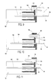
- the worker simply inserts the torsion spring member (136) into association with the spring securement mechanism.
- the user inserts the first portion (138) and the second portion (140) of the torsion spring member (136) through the slot (186) with the first portion (138) being aligned between the first rib (188) and the second rib (190).
- the second portion (140) being disposed proximate the roof (202) of the first body (182).
- FIGs 9, 10, and 11 depict the insertion process in detail.
- the hook portion (146) first is abutted against the ledge (194).
- the hook portion (146) is flexed inward due to contacting the ledge (194).
- the hook portion (146) elasticly flexes outward once the hook portion (146) is pressed past the ledge (194). Accordingly, the torsion spring member (136) is securely retained in place by the spring securement mechanism.
- the input mechanism (132) is then associated with the output mechanism (134).
- the alignment protrusion (208) is aligned with the alignment groove (154) thereby ensuring that the input mechanism (132) is properly oriented relative to the output mechanism (134).
- the lever portion (148) is thus properly nested within the cavity (164) of the face (162).
- the worker then inserts the axle (150) into the hole (206) of the second body (204). As the worker slides the axle (150) into the hole (206), the first finger (210) and the second finger (212) are cambered outward over the retention ring (158).
- the retention ring (158) will slid rearward of the first finger (210) and the second finger (212) thereby securing the axle (150) due to an abutting relationship between the first finger (210) and second finger (212) relative to the retention ring surface (160) of the retention ring (158).
- the axle (150) is passed through a bearing, not shown, mounted in leg connector (120b) and is then coupled to the hub (126b).
- the axle (150) includes a first claw (156) and a second claw, not shown, which engage the first orifice (240) and second orifice (242) respectively of the axle lock (232).
- the crank arm (130) is inserted into the channel (220).
- the crank arm may include a round ball, not shown, for engagement with the channel (220). However, to further simplify assembly and reduce the overall number of parts, the round ball has been found to be unnecessary. Accordingly, in a preferred embodiment, during operation the crank arm (130) alternately engages the first drive surface (222) and the second drive surface (224).
- crank arm (130) rotates along a circular path.
- the crank arm (130) alternatively engages the first drive surface (222) and the second drive surface (224).
- the input mechanism (132) converts the rotational motion of the crank arm (130) into an arcuately oscillating motion relative to the axle (150).
- the torsion spring member (136) is caused pivot relative to the axle (150).
- the torsion spring member (136) will be loaded by a force extending from one of the radiused edges (174, 176), depending on which direction the input mechanism (132) is pivoted relative to the output mechanism (134).
- Each radiused edge (174, 176) reduces friction as the lever portion (148) contacts the respective radiused edge (174, 176).
- the lever portion (148) becomes distanced from the respective radiused edge (174, 176) and is then engaged by one of the nubs (178, 180).
- Each nub (178, 180) extends outward relative to the respective wall (170, 172) and surface (166, 168) such that as the torsion spring member (136) unwinds, the lever portion (148) safely engages the respective radiused edge (174, 176) thereby reducing the opportunity for undesirable wear and friction.
- the present invention provides a multitude of advantages. As can be seen from the above, the present invention reduces the number of separate parts needed. As disclosed in a preferred embodiment, the drive flange (152) is preferably, integrally formed with the axle (150), the retention ring (158) is integrally formed on the axle (150), the input mechanism (132) is integrally formed together, each portion (148, 138, 142, 140, 144, and 146) of the torsion spring member (136) is integrally formed together. Ideally, the present invention reduces the part count of the swing drive mechanism (110). Although the preferred embodiment integrally forms several elements together, devices which integrally form fewer than all of the above members together are also contemplated by the present invention.
- the assembly of such a swing drive mechanism (110) substantially reduces the complexity in assembling such devices and also reduces the opportunity that such devices are misassembled.
- another advantage of this invention is that the swing drive mechanism (110) reduces wear and friction during operation. Specifically, friction and wear is reduced by the novel inclusion of the radiused edges (174, 176) and the nubs (178, 180) which extend outward into the cavity (164). Accordingly, the amount of energy required to operate such a devices is thereby reduced. In addition, failure due to friction is also reduced.
- the torsion spring member (136) of this invention uniquely includes a first portion (138) and a second portion (140). Both the first portion (138) and the second portion (140) are loaded once the lever portion (148) is engaged by the drive flange (152). Accordingly, the spring gradient achievable is approximately equal to that of a linear torsion spring of a single portion twice as long.
- the gradient for the torsion spring member (136) can be modified for a particular application by adjusting the length of either or both the first portion (138) or the second portion (140).
- the spring gradient is dependent upon the material utilized as well as the diameter of the torsion spring member (136). As such, the user of the present invention can substantially modify the diameters, lengths or material utilized to suit a particular application.
Landscapes
- Mechanical Operated Clutches (AREA)
- Transmission Devices (AREA)
- Rear-View Mirror Devices That Are Mounted On The Exterior Of The Vehicle (AREA)
- Seats For Vehicles (AREA)
Applications Claiming Priority (2)
| Application Number | Priority Date | Filing Date | Title |
|---|---|---|---|
| US09/104,286 US6193224B1 (en) | 1998-06-24 | 1998-06-24 | Swing drive mechanism for child's swing |
| US104286 | 1998-06-24 |
Publications (3)
| Publication Number | Publication Date |
|---|---|
| EP0966997A2 true EP0966997A2 (de) | 1999-12-29 |
| EP0966997A3 EP0966997A3 (de) | 2001-01-24 |
| EP0966997B1 EP0966997B1 (de) | 2006-10-11 |
Family
ID=22299640
Family Applications (1)
| Application Number | Title | Priority Date | Filing Date |
|---|---|---|---|
| EP99304733A Expired - Lifetime EP0966997B1 (de) | 1998-06-24 | 1999-06-17 | Antriebsvorrichtung für eine Schaukel |
Country Status (4)
| Country | Link |
|---|---|
| US (1) | US6193224B1 (de) |
| EP (1) | EP0966997B1 (de) |
| CA (1) | CA2275105A1 (de) |
| DE (1) | DE69933511T2 (de) |
Cited By (1)
| Publication number | Priority date | Publication date | Assignee | Title |
|---|---|---|---|---|
| WO2006058144A2 (en) | 2004-11-29 | 2006-06-01 | Wonderland Nurserygoods Co., Ltd. | Hanger mounts for child swing |
Families Citing this family (14)
| Publication number | Priority date | Publication date | Assignee | Title |
|---|---|---|---|---|
| US6561915B2 (en) * | 2001-10-09 | 2003-05-13 | Mattel, Inc. | Infant swing and method of using the same |
| US20030199329A1 (en) * | 2002-04-23 | 2003-10-23 | Steve Wood | Swing |
| US6875117B2 (en) * | 2002-11-26 | 2005-04-05 | Graco Children's Products Inc. | Swing drive mechanism |
| US7275996B2 (en) * | 2004-08-03 | 2007-10-02 | Simplicity, Inc. | Infant swing |
| US7381138B2 (en) * | 2004-08-03 | 2008-06-03 | Simplicity Inc. | Infant swing |
| CN101203287B (zh) * | 2005-03-07 | 2012-01-18 | 考可拉夫特公司 | 幼儿摇具和蹦具装置及其操作方法 |
| US8070617B2 (en) | 2007-03-13 | 2011-12-06 | Kolcraft Enterprises, Inc. | Child swing and jumper apparatus and methods of operating the same |
| US7905791B2 (en) * | 2007-06-29 | 2011-03-15 | Kids Ii, Inc. | Control device for a swing |
| CN101744479B (zh) * | 2008-12-07 | 2012-07-25 | 明门香港股份有限公司 | 婴幼儿弹跳座椅 |
| BRPI0923116A2 (pt) | 2008-12-12 | 2018-10-23 | Kids Ii Inc | balanço eletromagnético |
| CN204318176U (zh) | 2014-08-08 | 2015-05-13 | 儿童二代公司 | 用于儿童弹跳装置及婴儿支撑装置的控制设备 |
| US9775445B2 (en) | 2015-04-25 | 2017-10-03 | Kids Ii, Inc. | Collapsible swing frame |
| US11700953B2 (en) * | 2019-09-18 | 2023-07-18 | Wonderland Switzerland Ag | Child care apparatus |
| CN112515409B (zh) * | 2019-09-18 | 2025-02-07 | 明门瑞士股份有限公司 | 摇摆锁定结构与摇床 |
Family Cites Families (20)
| Publication number | Priority date | Publication date | Assignee | Title |
|---|---|---|---|---|
| US2810153A (en) * | 1953-03-30 | 1957-10-22 | Gen Motors Corp | Torque rod door counterbalance |
| GB877668A (en) | 1959-05-14 | 1961-09-20 | Ivor Samuel Wayne | Improvements in or relating to swings for babies or small children |
| GB1070921A (en) | 1962-08-09 | 1967-06-07 | Leonard James Norris | Improvements in or relating to swings |
| US3358659A (en) * | 1965-07-17 | 1967-12-19 | Gen Motors Corp | Internal combustion engine valve gear |
| GB1371481A (en) | 1972-07-10 | 1974-10-23 | Young Ho Kim | Electrically-operated swing |
| US4150829A (en) | 1977-05-09 | 1979-04-24 | Cates John A | Game apparatus |
| US4150820A (en) * | 1977-06-13 | 1979-04-24 | Hedstrom Co. | Motorized swing |
| US4181299A (en) * | 1978-01-09 | 1980-01-01 | Foster Edwin E | Spring powered swing |
| CA1115302A (en) | 1978-03-08 | 1981-12-29 | Gerico, Inc. | Pendulum swing |
| US4805902A (en) * | 1987-06-30 | 1989-02-21 | Spalding & Evenflo Companies, Inc. | Inclined-axis pendulum swing |
| US4911429A (en) | 1989-07-18 | 1990-03-27 | Ogbu Emmanuel K | Motorized swing |
| US5083773A (en) | 1990-08-27 | 1992-01-28 | Graco Children's Products, Inc. | Lobe spring motor for child's swing |
| US5172955A (en) | 1991-02-28 | 1992-12-22 | Gerry Baby Products Company | Bouncing infant seat reclining between upright position and recline position with distinct resilient element |
| CA2049580C (en) * | 1991-08-20 | 1997-04-01 | Yun Hui Zhang | Pressure balanced torsion system for a backrest and the like |
| US5378196A (en) | 1992-09-15 | 1995-01-03 | Cosco, Inc. | Child swing |
| US5376053A (en) | 1993-08-02 | 1994-12-27 | Ponder; Patricia D. | Remotely operated motorized swing |
| US5525113A (en) | 1993-10-01 | 1996-06-11 | Graco Childrens Products Inc. | Open top swing & control |
| DE19629030A1 (de) * | 1995-07-18 | 1997-02-27 | M & C Corp | Torsionsstabfederanordnung |
| US5833545A (en) * | 1996-08-28 | 1998-11-10 | Cosco, Inc. | Automatic pendulum-drive system |
| US5846136A (en) * | 1998-01-29 | 1998-12-08 | Wu; Sung-Tsun | Swing chair |
-
1998
- 1998-06-24 US US09/104,286 patent/US6193224B1/en not_active Expired - Fee Related
-
1999
- 1999-06-15 CA CA002275105A patent/CA2275105A1/en not_active Abandoned
- 1999-06-17 EP EP99304733A patent/EP0966997B1/de not_active Expired - Lifetime
- 1999-06-17 DE DE69933511T patent/DE69933511T2/de not_active Expired - Fee Related
Non-Patent Citations (1)
| Title |
|---|
| None |
Cited By (3)
| Publication number | Priority date | Publication date | Assignee | Title |
|---|---|---|---|---|
| WO2006058144A2 (en) | 2004-11-29 | 2006-06-01 | Wonderland Nurserygoods Co., Ltd. | Hanger mounts for child swing |
| JP2008521498A (ja) * | 2004-11-29 | 2008-06-26 | ワンダーランド ナーセリーグッズ コーポレイション リミテッド | 幼児用ブランコのハンガーマウント |
| EP1827638A4 (de) * | 2004-11-29 | 2009-12-16 | Wonderland Nursery Goods | Hängelager für eine kinderschaukel |
Also Published As
| Publication number | Publication date |
|---|---|
| DE69933511D1 (de) | 2006-11-23 |
| CA2275105A1 (en) | 1999-12-24 |
| EP0966997B1 (de) | 2006-10-11 |
| DE69933511T2 (de) | 2007-06-28 |
| US6193224B1 (en) | 2001-02-27 |
| EP0966997A3 (de) | 2001-01-24 |
Similar Documents
| Publication | Publication Date | Title |
|---|---|---|
| EP0966997A2 (de) | Antriebsvorrichtung für eine Schaukel | |
| US4780928A (en) | Spring biased hinge for spectacle frames | |
| CA1301624C (en) | Flexible backrest assembly for a chair | |
| EP0359406B1 (de) | Rückenlehnenbefestigung | |
| US6749236B2 (en) | Door handle device for a vehicle | |
| EP0552962B1 (de) | Klammeranordnung | |
| EP0620375A1 (de) | Wirbelhaken | |
| JP4948532B2 (ja) | 乗物の手すり | |
| US7047597B2 (en) | Hinge for folding ladders | |
| WO2000067868A1 (en) | Children's reclineable swing seat | |
| JP2001505849A (ja) | ウィンドウワイパー | |
| GB2238764A (en) | Rear view mirror for an automobile | |
| EP0285262B1 (de) | Blatt für Scheibenwischer | |
| JP4123553B2 (ja) | ドアアウトサイドハンドル装置 | |
| JPH0885357A (ja) | 操作ペダル | |
| US7367100B2 (en) | Method for manufacturing a stamper ball socket | |
| JP2004522345A (ja) | 調整可能マイクロホンブームを有するヘッドセット | |
| US4249579A (en) | Shaft for a weaving machine | |
| EP0872400A2 (de) | Haube für Kinderwagen | |
| US20020174504A1 (en) | Adapter for windshield wiper arms | |
| JPH09165111A (ja) | 板リンクチェーン | |
| AU669589B2 (en) | Eyeglass frame | |
| EP0463503B1 (de) | Reflektor für Fahrzeuge | |
| HUP0002222A2 (hu) | Hevedertekercselő szerkezet, mechanizmus egy ilyen hevedertekercselő szerkezetet tartalmazó redőny vagy roletta működtetéséhez, valamint eljárás egy ilyen hevedertekercselő szerkezet előállítására | |
| KR200239247Y1 (ko) | 버클의 회동장치 |
Legal Events
| Date | Code | Title | Description |
|---|---|---|---|
| PUAI | Public reference made under article 153(3) epc to a published international application that has entered the european phase |
Free format text: ORIGINAL CODE: 0009012 |
|
| AK | Designated contracting states |
Kind code of ref document: A2 Designated state(s): DE FR GB |
|
| AX | Request for extension of the european patent |
Free format text: AL;LT;LV;MK;RO;SI |
|
| RIC1 | Information provided on ipc code assigned before grant |
Free format text: 7A 63G 9/16 A, 7A 47D 13/10 B |
|
| PUAL | Search report despatched |
Free format text: ORIGINAL CODE: 0009013 |
|
| AK | Designated contracting states |
Kind code of ref document: A3 Designated state(s): AT BE CH CY DE DK ES FI FR GB GR IE IT LI LU MC NL PT SE |
|
| AX | Request for extension of the european patent |
Free format text: AL;LT;LV;MK;RO;SI |
|
| 17P | Request for examination filed |
Effective date: 20010724 |
|
| AKX | Designation fees paid |
Free format text: DE FR GB |
|
| 17Q | First examination report despatched |
Effective date: 20040216 |
|
| GRAP | Despatch of communication of intention to grant a patent |
Free format text: ORIGINAL CODE: EPIDOSNIGR1 |
|
| GRAS | Grant fee paid |
Free format text: ORIGINAL CODE: EPIDOSNIGR3 |
|
| GRAA | (expected) grant |
Free format text: ORIGINAL CODE: 0009210 |
|
| AK | Designated contracting states |
Kind code of ref document: B1 Designated state(s): DE FR GB |
|
| REG | Reference to a national code |
Ref country code: GB Ref legal event code: FG4D |
|
| REF | Corresponds to: |
Ref document number: 69933511 Country of ref document: DE Date of ref document: 20061123 Kind code of ref document: P |
|
| ET | Fr: translation filed | ||
| PLBE | No opposition filed within time limit |
Free format text: ORIGINAL CODE: 0009261 |
|
| STAA | Information on the status of an ep patent application or granted ep patent |
Free format text: STATUS: NO OPPOSITION FILED WITHIN TIME LIMIT |
|
| 26N | No opposition filed |
Effective date: 20070712 |
|
| PGFP | Annual fee paid to national office [announced via postgrant information from national office to epo] |
Ref country code: DE Payment date: 20080731 Year of fee payment: 10 |
|
| PGFP | Annual fee paid to national office [announced via postgrant information from national office to epo] |
Ref country code: FR Payment date: 20080617 Year of fee payment: 10 |
|
| REG | Reference to a national code |
Ref country code: FR Ref legal event code: ST Effective date: 20100226 |
|
| PG25 | Lapsed in a contracting state [announced via postgrant information from national office to epo] |
Ref country code: FR Free format text: LAPSE BECAUSE OF NON-PAYMENT OF DUE FEES Effective date: 20090630 |
|
| PG25 | Lapsed in a contracting state [announced via postgrant information from national office to epo] |
Ref country code: DE Free format text: LAPSE BECAUSE OF NON-PAYMENT OF DUE FEES Effective date: 20100101 |
|
| PGFP | Annual fee paid to national office [announced via postgrant information from national office to epo] |
Ref country code: GB Payment date: 20100625 Year of fee payment: 12 |
|
| GBPC | Gb: european patent ceased through non-payment of renewal fee |
Effective date: 20110617 |
|
| PG25 | Lapsed in a contracting state [announced via postgrant information from national office to epo] |
Ref country code: GB Free format text: LAPSE BECAUSE OF NON-PAYMENT OF DUE FEES Effective date: 20110617 |