EP0967135A2 - Vorrichtung und Verfahren zur Erzeugung eines gewünschten Rückstellmomentes für die Servolenkung eines Kraftfahrzeuges - Google Patents
Vorrichtung und Verfahren zur Erzeugung eines gewünschten Rückstellmomentes für die Servolenkung eines Kraftfahrzeuges Download PDFInfo
- Publication number
- EP0967135A2 EP0967135A2 EP99201911A EP99201911A EP0967135A2 EP 0967135 A2 EP0967135 A2 EP 0967135A2 EP 99201911 A EP99201911 A EP 99201911A EP 99201911 A EP99201911 A EP 99201911A EP 0967135 A2 EP0967135 A2 EP 0967135A2
- Authority
- EP
- European Patent Office
- Prior art keywords
- return torque
- steering
- revolution
- revolution offset
- unadjusted
- Prior art date
- Legal status (The legal status is an assumption and is not a legal conclusion. Google has not performed a legal analysis and makes no representation as to the accuracy of the status listed.)
- Granted
Links
- 238000004519 manufacturing process Methods 0.000 title claims 2
- 238000012360 testing method Methods 0.000 claims abstract description 38
- 230000004044 response Effects 0.000 claims abstract description 8
- 230000000977 initiatory effect Effects 0.000 claims abstract description 4
- 238000000034 method Methods 0.000 claims description 25
- 230000008859 change Effects 0.000 claims description 13
- 230000007704 transition Effects 0.000 claims description 12
- 239000007787 solid Substances 0.000 description 2
- 238000010998 test method Methods 0.000 description 2
- 230000009471 action Effects 0.000 description 1
- 230000003247 decreasing effect Effects 0.000 description 1
- 230000000694 effects Effects 0.000 description 1
- 230000014509 gene expression Effects 0.000 description 1
- 230000009191 jumping Effects 0.000 description 1
- 230000007246 mechanism Effects 0.000 description 1
- 230000008569 process Effects 0.000 description 1
- 238000005096 rolling process Methods 0.000 description 1
Images


Classifications
-
- B—PERFORMING OPERATIONS; TRANSPORTING
- B62—LAND VEHICLES FOR TRAVELLING OTHERWISE THAN ON RAILS
- B62D—MOTOR VEHICLES; TRAILERS
- B62D5/00—Power-assisted or power-driven steering
- B62D5/04—Power-assisted or power-driven steering electrical, e.g. using an electric servo-motor connected to, or forming part of, the steering gear
- B62D5/0457—Power-assisted or power-driven steering electrical, e.g. using an electric servo-motor connected to, or forming part of, the steering gear characterised by control features of the drive means as such
- B62D5/046—Controlling the motor
- B62D5/0466—Controlling the motor for returning the steering wheel to neutral position
-
- B—PERFORMING OPERATIONS; TRANSPORTING
- B62—LAND VEHICLES FOR TRAVELLING OTHERWISE THAN ON RAILS
- B62D—MOTOR VEHICLES; TRAILERS
- B62D15/00—Steering not otherwise provided for
- B62D15/02—Steering position indicators ; Steering position determination; Steering aids
- B62D15/021—Determination of steering angle
- B62D15/0245—Means or methods for determination of the central position of the steering system, e.g. straight ahead position
Definitions
- the technical field of this invention is the determination of a desired return torque in a vehicle power steering system having a total range of steering position greater than the output range of a rotational position sensor.
- Some vehicle power steering systems use an actuator coupled to the steering shaft to provide power assist in vehicle steering. It is often desirable in such systems to provide a return torque command to the actuator so as to help return the steering gear to a centered position and provide a stable steering feel to the vehicle operator. Such a return torque command is generated as a function of steering position as shown in the graph of FIG. 4, provided the steering position is known.
- Rotational position sensors having high resolution and other desirable characteristics may be coupled to the steering shaft to provide an output voltage varying in a substantially linear manner from a first voltage to a second voltage through a rollover angle comprising an entire 360 degree rotation or some sub-multiple thereof.
- the steering shaft typically rotates through a plurality of such revolutions or sub-multiple angles, and therefore a plurality of repetitions of the rollover angle, as the rack is moved from one end to the other of its operational range.
- a sensor directly coupled to the steering shaft for maximum resolution in the output signal is similarly rotated through a plurality of repetitions of the output voltage range and produces a rollover transition at the end of each repetition when the voltage jumps from one extreme to the other.
- the output of a sensor so coupled does not by itself provide a unique absolute steering position; rather, it provides a set of steering positions separated by a rollover angle corresponding to the full output voltage range. It is thus necessary, in order to know the absolute rotational position, to compensate the sensor output signal for such rollover transitions.
- an offset parameter must also generally be generated every time a new vehicle ignition cycle is initiated, since the sensor may have been rotated into a different range of its output when the ignition was off with no rollover transition being sensed.
- the method and apparatus of this invention determines an absolute steering position and return torque for a vehicle power steering system having a steering shaft with a rotational position sensor providing signal rollover so that each sensor output indicates a plurality of potential absolute steering positions separated from each other by multiples of a rollover angle.
- the method is performed by the apparatus upon each initiation of vehicle operation and begins by selecting, as an unadjusted steering position, one of the plurality of steering positions corresponding to an initial sensor output.
- This unadjusted steering position is repeatedly updated in response to output changes of the rotational position sensor, including sensed rollover transitions, so that it spans the full range of steering position, although it may be incorrect by a revolution offset which is an integer multiple of the rollover angle.
- the updated value is repeatedly tested against a predetermined set of revolution offsets to determine which of these offsets, in combination with the updated value, produces a steering position outside the known total range of steering position. Any such revolution offset of the predetermined set found to be impossible is excluded; and, when only one is left, it is latched as the final revolution offset. After this occurs, absolute steering position is derived from this final revolution offset in combination with the unadjusted steering position.
- the vehicle power steering system has an actuator coupled to the steering shaft for the provision of a return torque.
- a first return torque command is provided to the actuator to produce a predetermined first return torque.
- the first return torque command is preferably derived from a temporary revolution offset in combination with the updated unadjusted steering position; and in a preferred embodiment, the temporary revolution offset is preferably first given a value which, in combination with the updated unadjusted steering position, provides a return torque of zero.
- an absolute steering position is derived from the one final revolution offset in combination with the unadjusted steering position; and a second return torque command is derived from the absolute steering position, and provided to the actuator to produce a second return torque.
- the temporary revolution offset is preferably walked incrementally toward the one final revolution offset, with return torque derived from the temporary revolution offset so changed in combination with the updated unadjusted steering position as long as the derived return torque is in the correct centering direction, until either (1) the temporary revolution offset arrives within a first predetermined small distance of the one final revolution offset, or (2) when a true absolute steering position, derived from the one remaining revolution offset in combination with the updated unadjusted position, arrives within a second predetermined small distance of the center position, whichever occurs first.
- the absolute steering position and return torque are derived from the final revolution offset in combination with the unadjusted steering position.
- a usable revolution offset may be set as a target before the one final revolution offset is identified and the temporary revolution offset may be walked incrementally toward the usable revolution offset, with return torque derived from the temporary revolution offset so changed in combination with the updated unadjusted steering position as long as the derived return torque is in the correct centering direction.
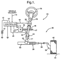
- a motor vehicle 40 is provided with a power steering system 24, which in this embodiment is an electric power steering system.
- Power steering system 24 may comprise a conventional rack and pinion steering mechanism 36, which includes a toothed rack 50 and a pinion gear (not shown) under gear housing 52.
- a hand wheel 26 is turned by a vehicle operator, an upper steering shaft 29 turns a lower shaft 51 through a universal joint 34; and lower steering shaft 51 turns the pinion gear.
- Rotation of the pinion gear moves the rack, which moves the tie rods 38 (only one shown), which move steering knuckles 39 (only one shown) to turn steering wheels 42 (only one shown).
- Controller 16 receives electric power from a vehicle electric power source 10 through a line 12, a signal representative of the vehicle velocity on line 14, and steering pinion gear angle signal from a rotational position sensor 32 on line 20.
- a torque sensor 28 senses the torque applied to hand wheel 26 by the vehicle operator and provides a handwheel torque signal to controller 16 on line 18.
- rotor position signals for each phase are generated within motor 46 and provided over bus 30 to controller 16.
- controller 16 In response to the vehicle velocity, operator torque, steering pinion gear angle and rotor position signals received, controller 16 derives desired motor currents and provides such currents through a bus 22 to motor 46, which supplies torque assist to steering shaft 29, 51 through worm 47 and worm gear 48. If torque sensor 28 is the type which requires upper steering shaft 29 to be separated at the sensor between upper and lower sections allowing some range of rotational independence, both rotational position sensor 32 and worm gear 48 are associated with the lower section of the steering shaft, below torque sensor 28 as shown.
- Rack 50 and its associated pinion gear of steering system 24 have a center position, in which steering wheels 42 are directed straight ahead relative to vehicle 40. It is an object of power steering system 24 to provide a return torque that assists in returning the steering system to a center position from either side thereof and provides the vehicle operator with a stable steering response and feel. In power steering system 24, this return torque is generated by electric motor 46; and a return torque component of the total desired torque signal is generated in controller 16. The desired return torque is typically programmed into control 16 as a function of the absolute steering position: that is, the deviation in both directions from center of rack 50 and the pinion gear. Thus, an accurate signal of steering position must be derived from rotational position sensor 32.
- Sensor 32 is preferably a rotational position sensor which provides an output voltage corresponding to rotational angle through a complete revolution of lower steering shaft 51, and thus of the pinion gear.
- Sensor 32 will be assumed that lower steering shaft 51, the rotating portion of sensor 32 and the pinion gear rotate together, as a unit, through the same rotational angle, to control the direction of steering wheels 42.
- full rack movement of the steering system 24 may require three to five full turns of steering shaft 51 and the pinion gear, and thus of the rotatable portion of sensor 32.
- sensor 32 is thus set up to provide a unique, continuously varying voltage between rotational positions 180 degrees to the left and right of the center position, at which point the voltage jumps or "rolls over” to repeat the variation with further rotation in the same direction.
- sensor 32 may be set up to provide the unique, continuously varying voltage over only half (180 degrees) or some other fraction of one full rotation, thus producing an even greater number of rollover events over the full range of rack movement.
- the output signal of sensor 32 by itself is ambiguous in that a given output voltage may correspond to a plurality of rack or steering positions, only one of which is correct.
- the apparatus of this invention performs an algorithm in controller 16, which may be embodied in a programmed digital computer or a custom digital processor.
- controller 16 may be embodied in a programmed digital computer or a custom digital processor.
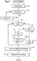
- the algorithm is described with reference to the flow charts of FIG. 5-7, together with the graphs of FIG. 2, 3 and 5.
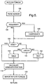
- routine RETURN TORQUE begins by reading and storing the sensor output at 102.
- the sensor output is a voltage, which is converted into a digital word by A/D converter apparatus in controller 16.
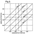
- This digital word represents an angle as shown in FIG. 3, which shows a graphical representation of the output of sensor 32 over the full range of absolute steering position.
- the graph is horizontally divided into several sections of linearly increasing (from left to right) output over 360 rotational degrees, with the voltage output jumping between the highest and lowest values in a rollover transition between each two adjacent sections.
- the total rotational angle through which sensor 32 varies continuously before rolling over - 360 degrees in this embodiment - is referred to herein as the rollover angle.
- the center section of the graph is itself centered on zero degrees, so that it spans the range -180 ⁇ ⁇ ⁇ +180 degrees. For the initial sensor output reading, it is assumed that the value is on this center section of the graph.
- the sensor output is tested for rollover at 104; and, if required, rollover compensation is performed at 106.
- a rollover transition can be detected by comparing the present sensor output with a previous sensor output to detect when the value jumps between the extremes of its range.
- Rollover compensation provides a step increase of +360 degrees, in this embodiment, when an increasing sensor output rolls over from +180 to -180 degrees (corresponding to a rollover transition from its maximum voltage to its minimum voltage) and a similar but opposite step increase of -360 degrees when a decreasing sensor output rolls over from -180 to +180 degrees.
- An additional rollover transition in the same direction provides an additional 360 degree rollover compensating step change. The result is a full scale output as shown in the center line 90 of FIG. 3.
- the true value of Revolution Offset is zero or some multiple of the rollover angle - 360 degrees in this embodiment - and may be expressed in terms of a Revolution Index (e.g., +2, +1, 0, -1, -2) times the rollover angle.
- a Revolution Index e.g., +2, +1, 0, -1, -2
- the Revolution Offset is not rollover compensation, which changes with every rollover of the sensor output signal. Rather, it relates the line of the true Absolute Position in the graph of FIG. 3 to the Unadjusted Position of center line 90 over the full range of rack movement and, when determined with certainty and phased in, will not change for the remainder of the ignition cycle.
- a DONE flag is checked at 108 to see if the final Revolution Offset is to be used in the equation for Absolute Position. This will be the case only when the final (presumed true) value of Revolution Offset has been determined and fully phased in; and this process typically requires many cycles of the program.
- the DONE flag is thus initialized in a not set condition and will typically remain so for many cycles of the program.
- a LATCH flag is checked at 110.
- the LATCH flag will be set only after the final value of Revolution Offset has been determined; and this flag also will be initialized as not set and likely remain so for a number of program cycles thereafter.
- the program runs a subroutine TEST at step 112. In this subroutine certain tests are performed to advance the determination of the final value of Revolution Offset and a temporary value of Revolution Offset is provided. Subroutine TEST will be described at a later point in this description.
- Subroutine TEST is described in detail with reference to the flow chart of FIG. 6.
- the subroutine first performs a series of tests referred to as TEST AND EXCLUDE at step 120 in which a predetermined number of potential values of Revolution Offset are tested for possibility in view of the value of Unadjusted Position and the maximum travel of rack 50 from its center position. Assuming potential Revolution Offset Indexes of 0, +1, -1, +2 and -2, a flag for each is set during initialization and, as each is found to be impossible, its flag is reset. The tests are demonstrated below.
- a Revolution Offset of +1 is impossible and thus eliminated if either of the following is true: Unadjusted Position ⁇ (+360 - Max Travel), or Unadjusted Position > (+360 + Max Travel).
- a Revolution Offset of -1 is impossible and thus eliminated if either of the following is true: Unadjusted Position > (-360 + Max Travel), or Unadjusted Position ⁇ (-360 - Max Travel).
- Revolution Offset is made equal to the Unadjusted Position.
- the program next returns from subroutine TEST and calculates Absolute Position, its value will be zero, regardless of the sensor output. This is a convenient way of preventing the provision of Return Torque, since it "fools" the torque determining part of the algorithm into considering the steering wheels 42 to be centered. However, if other information is available which, in the opinion of the system designer, will provide a usable temporary return torque value, it could be introduced in step 124 instead.
- the value of Revolution Offset has not been zero but, as described above, has been set equal to Unadjusted Position to produce zero Return Torque.
- the desired Return Torque is preferably phased in slowly and smoothly. This is accomplished by a subroutine WALK, which is called at step 114 before Absolute Position is calculated at 116.
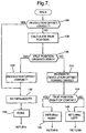
- Subroutine WALK is described by the flow chart of FIG. 7.
- the subroutine essentially "walks" the value of Revolution Offset in incremental steps from the value being used at the time a usable or new value of Revolution Offset Index is derived toward the target value corresponding to the derived Revolution Offset Index until the first of the following to occur: (1) the target value of Revolution Offset is reached, or (2) a true center position is reached.
- a Return Torque is derived based on the Absolute Position calculated from the walking value of Revolution Offset; but it is used only if it would actually provide a Return Torque in the direction of the center position.
- solid line 160a - 160c shows the desired return torque as a function of True Position for a specific example in which a last remaining Revolution Index of zero is latched at a time when the Unadjusted Position is +144 degrees and the Revolution Offset is thus also +144 degrees.
- the True Position is the value of Absolute Position corresponding to the targeted Revolution Offset: a value associated with the present usable value of Index.
- the word "true” is used in comparison with the Absolute Position, which is derived during the walk to provide an intended steering "feel" and does not actually represent a true steering position until the walk has ended.
- the DONE flag is set at step 134, and the program returns from subroutine WALK, calculates the Absolute Position at step 116 and derives the corresponding Return Torque at step 118 of FIG. 5.
- the DONE flag consulted at step 108 will cause subroutines TEST and WALK to be skipped. However, this is unlikely to occur in the first cycles of the routine.
- either or both tests may be expressed as whether the value being tested is within a predetermined distance of zero, since a small sudden change in Return Torque produced by a non-zero Absolute Position within the predetermined range about zero may be essentially negligible.
- the WALK subroutine will continue to be called from routine RETURN TORQUE, with Return Torque provided or not as described above, until one of the conditions for the end of the walk is met and the DONE flag set, after which no further testing or walking is done for the remainder of the ignition cycle.
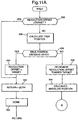
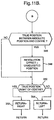
- FIG. 11A and 11B An alternative subroutine WALK is shown in FIG. 11A and 11B.
- This version of WALK provides an additional way to shorten the time required for the walk.
- Steps 330 - 342 are identical with the similarly numbered steps 230 - 243 in FIG. 7. But even if the first and second conditions have not ended the walk, there is still a possibility that the walk can be shortened. If the vehicle handwheel has been turned in the direction of center faster than the walk has proceeded, the True Position might be closer to center than the Absolute Position and on the same side. With reference to FIG. 8, the Absolute Position is in the range of dashed line 160d.
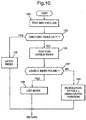
- FIG. 9 A variation of routine RETURN TORQUE is shown in FIG. 9, which also includes a variation of the TEST subroutine in FIG. 10. This version is appropriate for an embodiment of the power steering system in which, due to other reliable information, Return Torque is authorized before the Revolution Offset is latched.
- the routine of FIG. 9 is identical with that of FIG. 5 in steps 102 through 110 and steps 114 through 118. However, it differs in the procedure followed if the LATCH flag is not found set at 110. In this case, a TEST subroutine is performed that is shown in FIG. 10, to be described below.
- steps 120 and 122 are identical to those of FIG. 6. From step 122, if there is only one Index left, the LATCH flag is set at 126; and subroutine TEST is exited back to routine RETURN TORQUE. This outcome provides the true value of Revolution Offset and initiates a walk as previously described. From step 122 if there is more than one Index left, the subroutine seeks a usable Index at 125. This can be through a different test procedure not described herein, and may or may not be restricted to the remaining Indexes of step 120. If a usable Index is found at 127, it is set as the walk target at 128 before the subroutine is exited. Return Torque is authorized, but no Index is latched.
- Revolution Offset is set equal to Unadjusted Position at 126 before subroutine TEST is exited.
- FIG. 9, 10 and 7 produces the same result as that of FIG. 5, 6 and 7 before in initial operation, with no Index used and no Return Torque authorized while testing, and after an Index is latched, with Return Torque authorized in a correct return direction and testing stopped while the Revolution Offset is walked to the value determined by the latched Index.
- a usable Index may be found by an alternate test or other method and used, with Return Torque authorized in the correct return direction while walking Revolution Offset toward a value determined by the usable Index while testing is continued. If an Index is finally latched which is different from the Index being used, the target Revolution Offset is changed and the walk continues. This permits the use of another test procedure which provides a usable Revolution Offset sooner in some driving modes with a final determination provided by the tests of step 122.
Landscapes
- Engineering & Computer Science (AREA)
- Chemical & Material Sciences (AREA)
- Combustion & Propulsion (AREA)
- Transportation (AREA)
- Mechanical Engineering (AREA)
- Steering Control In Accordance With Driving Conditions (AREA)
- Power Steering Mechanism (AREA)
Applications Claiming Priority (2)
| Application Number | Priority Date | Filing Date | Title |
|---|---|---|---|
| US103603 | 1993-08-06 | ||
| US09/103,603 US6050360A (en) | 1998-06-24 | 1998-06-24 | Apparatus and method for producing a desired return torque in a vehicle power steering system having a rotational steering position sensor |
Publications (3)
| Publication Number | Publication Date |
|---|---|
| EP0967135A2 true EP0967135A2 (de) | 1999-12-29 |
| EP0967135A3 EP0967135A3 (de) | 2002-06-12 |
| EP0967135B1 EP0967135B1 (de) | 2003-10-15 |
Family
ID=22296045
Family Applications (1)
| Application Number | Title | Priority Date | Filing Date |
|---|---|---|---|
| EP99201911A Expired - Lifetime EP0967135B1 (de) | 1998-06-24 | 1999-06-15 | Vorrichtung und Verfahren zur Erzeugung eines gewünschten Rückstellmomentes für die Servolenkung eines Kraftfahrzeuges |
Country Status (5)
| Country | Link |
|---|---|
| US (1) | US6050360A (de) |
| EP (1) | EP0967135B1 (de) |
| JP (1) | JP3348044B2 (de) |
| BR (1) | BR9902555A (de) |
| DE (1) | DE69912028T2 (de) |
Cited By (9)
| Publication number | Priority date | Publication date | Assignee | Title |
|---|---|---|---|---|
| WO2002082621A1 (en) * | 2001-04-03 | 2002-10-17 | Emerson Electric Co. | Electric power steering system including a segmented stator switched reluctance motor |
| EP1332943A1 (de) * | 2002-01-25 | 2003-08-06 | Toyoda Koki Kabushiki Kaisha | Elektrische Servolenkung |
| US6744166B2 (en) | 2001-01-04 | 2004-06-01 | Emerson Electric Co. | End cap assembly for a switched reluctance electric machine |
| US6897591B2 (en) | 2001-03-26 | 2005-05-24 | Emerson Electric Co. | Sensorless switched reluctance electric machine with segmented stator |
| US7012350B2 (en) | 2001-01-04 | 2006-03-14 | Emerson Electric Co. | Segmented stator switched reluctance machine |
| EP1873039A3 (de) * | 2006-06-28 | 2008-10-22 | Jungheinrich Aktiengesellschaft | Verfahren zur Einstellung eines Lenkbereichs bei einer elektrischen Lenkung für ein Flurförderzeug |
| EP1658556A4 (de) * | 2003-08-28 | 2008-12-31 | Motorola Inc | Fehlererkennung bei einem elektrischen servolenkung-system |
| US7950115B2 (en) | 2005-12-30 | 2011-05-31 | A. Raymond Et Cie | Device for fastening an add-on part to a support part |
| WO2020007472A1 (de) * | 2018-07-05 | 2020-01-09 | Gkn Automotive Ltd. | Verfahren zur regelung eines antriebssystems für eine achse eines kraftfahrzeuges |
Families Citing this family (61)
| Publication number | Priority date | Publication date | Assignee | Title |
|---|---|---|---|---|
| JP2000198456A (ja) * | 1998-12-28 | 2000-07-18 | Honda Motor Co Ltd | 電動パワ―ステアリング装置 |
| US6364050B1 (en) * | 1999-01-15 | 2002-04-02 | Trw Lucas Varity Electric Steering Ltd. | Electrical power assisted steering assemblies |
| US6554094B1 (en) * | 1999-12-17 | 2003-04-29 | Meritor Heavy Vehicle Systems, Llc | Method and system for independently electronically controlling steering of vehicle wheels |
| DE19961886B4 (de) * | 1999-12-20 | 2005-06-16 | Sauer-Danfoss Holding Aps | Lenkeinrichtung |
| US6834218B2 (en) | 2001-11-05 | 2004-12-21 | Ford Global Technologies, Llc | Roll over stability control for an automotive vehicle |
| US6263261B1 (en) * | 1999-12-21 | 2001-07-17 | Ford Global Technologies, Inc. | Roll over stability control for an automotive vehicle |
| US6367576B1 (en) * | 2000-03-09 | 2002-04-09 | Delphi Technologies, Inc. | Method and system for applying return torque in a vehicle power steering system |
| US6408234B1 (en) * | 2000-09-07 | 2002-06-18 | Delphi Technologies, Inc. | Automatic compensation for electric power steering hysteresis |
| US7233236B2 (en) * | 2000-09-25 | 2007-06-19 | Ford Global Technologies, Llc | Passive wheel lift identification for an automotive vehicle using operating input torque to wheel |
| US6904350B2 (en) | 2000-09-25 | 2005-06-07 | Ford Global Technologies, Llc | System for dynamically determining the wheel grounding and wheel lifting conditions and their applications in roll stability control |
| US7109856B2 (en) * | 2000-09-25 | 2006-09-19 | Ford Global Technologies, Llc | Wheel lifted and grounded identification for an automotive vehicle |
| US6356188B1 (en) | 2000-09-25 | 2002-03-12 | Ford Global Technologies, Inc. | Wheel lift identification for an automotive vehicle |
| US7132937B2 (en) | 2000-09-25 | 2006-11-07 | Ford Global Technologies, Llc | Wheel lift identification for an automotive vehicle using passive and active detection |
| US6389343B1 (en) | 2000-09-29 | 2002-05-14 | Caterpillar Inc. | Steering resistance device |
| US6700284B2 (en) | 2001-03-26 | 2004-03-02 | Emerson Electric Co. | Fan assembly including a segmented stator switched reluctance fan motor |
| US6584813B2 (en) | 2001-03-26 | 2003-07-01 | Emerson Electric Co. | Washing machine including a segmented stator switched reluctance motor |
| US6637543B2 (en) | 2001-02-14 | 2003-10-28 | Delphi Technologies, Inc. | Oversteer control for a motor vehicle |
| US6817439B2 (en) * | 2001-04-04 | 2004-11-16 | Delphi Technologies, Inc. | Method for controlling an electric power assist steering system with low hysteresis and torque ripple |
| US6655493B2 (en) * | 2001-04-04 | 2003-12-02 | Delphi Technologies, Inc. | Steering column with non-compliant torque sensor |
| US6588541B2 (en) | 2001-05-30 | 2003-07-08 | Delphi Technologies, Inc. | Soft-disable damping for electric power steering |
| US6535805B2 (en) * | 2001-08-10 | 2003-03-18 | Delphi Technologies, Inc. | Robust determination of hand-wheel position |
| US6965820B2 (en) * | 2001-09-18 | 2005-11-15 | Delphi Technologies, Inc. | Robust steering-pull torque compensation |
| US6654674B2 (en) * | 2001-11-21 | 2003-11-25 | Ford Global Technologies, Llc | Enhanced system for yaw stability control system to include roll stability control function |
| US6556908B1 (en) | 2002-03-04 | 2003-04-29 | Ford Global Technologies, Inc. | Attitude sensing system for an automotive vehicle relative to the road |
| US7194351B2 (en) * | 2002-08-01 | 2007-03-20 | Ford Global Technologies, Llc | System and method for determining a wheel departure angle for a rollover control system |
| US7079928B2 (en) * | 2002-08-01 | 2006-07-18 | Ford Global Technologies, Llc | System and method for determining a wheel departure angle for a rollover control system with respect to road roll rate and loading misalignment |
| US7302331B2 (en) * | 2002-08-01 | 2007-11-27 | Ford Global Technologies, Inc. | Wheel lift identification for an automotive vehicle |
| US7085639B2 (en) * | 2002-08-01 | 2006-08-01 | Ford Global Technologies, Llc | System and method for characterizing the road bank for vehicle roll stability control |
| US7003389B2 (en) * | 2002-08-01 | 2006-02-21 | Ford Global Technologies, Llc | System and method for characterizing vehicle body to road angle for vehicle roll stability control |
| US6941205B2 (en) * | 2002-08-01 | 2005-09-06 | Ford Global Technologies, Llc. | System and method for deteching roll rate sensor fault |
| DE10235567A1 (de) * | 2002-08-03 | 2004-02-19 | Robert Bosch Gmbh | Vorrichtung zur Erkennung eines Überrollvorgangs |
| US6963797B2 (en) * | 2002-08-05 | 2005-11-08 | Ford Global Technologies, Llc | System and method for determining an amount of control for operating a rollover control system |
| US7085642B2 (en) * | 2002-08-05 | 2006-08-01 | Ford Global Technologies, Llc | Method and system for correcting sensor offsets |
| US6961648B2 (en) | 2002-08-05 | 2005-11-01 | Ford Motor Company | System and method for desensitizing the activation criteria of a rollover control system |
| US7430468B2 (en) * | 2002-08-05 | 2008-09-30 | Ford Global Technologies, Llc | System and method for sensitizing the activation criteria of a rollover control system |
| US20040024505A1 (en) * | 2002-08-05 | 2004-02-05 | Salib Albert Chenouda | System and method for operating a rollover control system in a transition to a rollover condition |
| US20040024504A1 (en) * | 2002-08-05 | 2004-02-05 | Salib Albert Chenouda | System and method for operating a rollover control system during an elevated condition |
| DE10255469B4 (de) * | 2002-11-28 | 2017-05-24 | Robert Bosch Gmbh | Modellbasierte Bestimmung eines eindeutigen Winkels aus einem nicht eindeutigen Sensorsignal |
| US7239949B2 (en) * | 2003-02-26 | 2007-07-03 | Ford Global Technologies, Llc | Integrated sensing system |
| US9162656B2 (en) * | 2003-02-26 | 2015-10-20 | Ford Global Technologies, Llc | Active driven wheel lift identification for an automotive vehicle |
| US7653471B2 (en) * | 2003-02-26 | 2010-01-26 | Ford Global Technologies, Llc | Active driven wheel lift identification for an automotive vehicle |
| US7136731B2 (en) * | 2003-06-11 | 2006-11-14 | Ford Global Technologies, Llc | System for determining vehicular relative roll angle during a potential rollover event |
| WO2004108453A2 (en) * | 2003-06-11 | 2004-12-16 | Cambridge Consultants Ltd | Handwheel-operated device |
| US7308350B2 (en) * | 2004-05-20 | 2007-12-11 | Ford Global Technologies, Llc | Method and apparatus for determining adaptive brake gain parameters for use in a safety system of an automotive vehicle |
| US7451032B2 (en) * | 2004-06-02 | 2008-11-11 | Ford Global Technologies, Llc | System and method for determining desired yaw rate and lateral velocity for use in a vehicle dynamic control system |
| US7640081B2 (en) * | 2004-10-01 | 2009-12-29 | Ford Global Technologies, Llc | Roll stability control using four-wheel drive |
| US7668645B2 (en) | 2004-10-15 | 2010-02-23 | Ford Global Technologies | System and method for dynamically determining vehicle loading and vertical loading distance for use in a vehicle dynamic control system |
| US7715965B2 (en) | 2004-10-15 | 2010-05-11 | Ford Global Technologies | System and method for qualitatively determining vehicle loading conditions |
| US7660654B2 (en) | 2004-12-13 | 2010-02-09 | Ford Global Technologies, Llc | System for dynamically determining vehicle rear/trunk loading for use in a vehicle control system |
| US7480547B2 (en) | 2005-04-14 | 2009-01-20 | Ford Global Technologies, Llc | Attitude sensing system for an automotive vehicle relative to the road |
| US7590481B2 (en) * | 2005-09-19 | 2009-09-15 | Ford Global Technologies, Llc | Integrated vehicle control system using dynamically determined vehicle conditions |
| FR2892086B1 (fr) * | 2005-10-19 | 2009-08-21 | Peugeot Citroen Automobiles Sa | Systeme d'aide a la manoeuvre pour un vehicule automobile. |
| US8121758B2 (en) * | 2005-11-09 | 2012-02-21 | Ford Global Technologies | System for determining torque and tire forces using integrated sensing system |
| US7600826B2 (en) * | 2005-11-09 | 2009-10-13 | Ford Global Technologies, Llc | System for dynamically determining axle loadings of a moving vehicle using integrated sensing system and its application in vehicle dynamics controls |
| US20080024028A1 (en) * | 2006-07-27 | 2008-01-31 | Islam Mohammad S | Permanent magnet electric motor |
| US7543679B2 (en) * | 2006-07-28 | 2009-06-09 | Delphi Technologies, Inc. | Compensation of periodic sensor errors in electric power steering systems |
| US7549504B2 (en) * | 2006-07-28 | 2009-06-23 | Delphi Technologies, Inc. | Quadrant dependent active damping for electric power steering |
| US7725227B2 (en) * | 2006-12-15 | 2010-05-25 | Gm Global Technology Operations, Inc. | Method, system, and apparatus for providing enhanced steering pull compensation |
| EP1990256B1 (de) * | 2007-05-08 | 2011-06-15 | Jtekt Corporation | Elektrische Servolenkung |
| PL1992549T3 (pl) * | 2007-05-18 | 2013-03-29 | Gm Global Tech Operations Llc | Sposób określania bezwzględnego położenia obrotowego kolumny kierownicy pojazdu |
| KR101484271B1 (ko) * | 2011-12-22 | 2015-01-19 | 주식회사 만도 | 전동식 파워 스티어링 시스템 및 그의 조향각 검증 방법 |
Family Cites Families (13)
| Publication number | Priority date | Publication date | Assignee | Title |
|---|---|---|---|---|
| US4825972A (en) * | 1986-02-25 | 1989-05-02 | Honda Giken Kogyo Kabushiki Kaisha | Steering system for vehicles |
| JPH0624953B2 (ja) * | 1986-04-08 | 1994-04-06 | 本田技研工業株式会社 | 電動式パワ−ステアリング装置 |
| JP2604620B2 (ja) * | 1988-03-15 | 1997-04-30 | 富士重工業株式会社 | 車両用動力操舵装置の制御装置 |
| US4979114A (en) * | 1988-04-21 | 1990-12-18 | Fuji Jukogyo Kabushiki Kaisha | Motor control apparatus for electric power steering system |
| FR2633889B1 (fr) * | 1988-07-05 | 1993-08-13 | Bendix Electronics Sa | Procede et dispositif de mesure de l'angle de rotation de l'arbre de direction d'un vehicule automobile |
| JPH02248811A (ja) * | 1989-03-22 | 1990-10-04 | Fuji Heavy Ind Ltd | 車両用舵角センサの絶対舵角検出方法 |
| JP2507598B2 (ja) * | 1989-05-15 | 1996-06-12 | 日産自動車株式会社 | 中立舵角推定装置 |
| JP2913852B2 (ja) * | 1991-01-28 | 1999-06-28 | 日産自動車株式会社 | 操舵角センサフェイル検出装置 |
| US5422810A (en) * | 1994-05-05 | 1995-06-06 | Ford Motor Company | Method and apparatus for determining steering position of automotive steering mechanism |
| US5732372A (en) * | 1995-06-09 | 1998-03-24 | Ford Global Technologies, Inc. | Method for determining a center position of a vehicle steering system |
| US5790966A (en) * | 1996-04-01 | 1998-08-04 | Ford Global Technologies, Inc. | Method for determining steering position of automotive steering mechanism |
| US5787375A (en) * | 1996-04-01 | 1998-07-28 | Ford Global Technologies, Inc. | Method for determining steering position of automotive steering mechanism |
| US5857160A (en) * | 1996-05-23 | 1999-01-05 | General Motors Corporation | Sensor-responsive control method and apparatus |
-
1998
- 1998-06-24 US US09/103,603 patent/US6050360A/en not_active Expired - Lifetime
-
1999
- 1999-06-15 DE DE69912028T patent/DE69912028T2/de not_active Expired - Lifetime
- 1999-06-15 EP EP99201911A patent/EP0967135B1/de not_active Expired - Lifetime
- 1999-06-23 JP JP17626699A patent/JP3348044B2/ja not_active Expired - Fee Related
- 1999-06-24 BR BR9902555-8A patent/BR9902555A/pt unknown
Cited By (12)
| Publication number | Priority date | Publication date | Assignee | Title |
|---|---|---|---|---|
| US6744166B2 (en) | 2001-01-04 | 2004-06-01 | Emerson Electric Co. | End cap assembly for a switched reluctance electric machine |
| US7012350B2 (en) | 2001-01-04 | 2006-03-14 | Emerson Electric Co. | Segmented stator switched reluctance machine |
| US6897591B2 (en) | 2001-03-26 | 2005-05-24 | Emerson Electric Co. | Sensorless switched reluctance electric machine with segmented stator |
| WO2002082621A1 (en) * | 2001-04-03 | 2002-10-17 | Emerson Electric Co. | Electric power steering system including a segmented stator switched reluctance motor |
| EP1332943A1 (de) * | 2002-01-25 | 2003-08-06 | Toyoda Koki Kabushiki Kaisha | Elektrische Servolenkung |
| US6856869B2 (en) | 2002-01-25 | 2005-02-15 | Toyoda Koki Kabushiki Kaisha | Electric power steering device |
| EP1658556A4 (de) * | 2003-08-28 | 2008-12-31 | Motorola Inc | Fehlererkennung bei einem elektrischen servolenkung-system |
| US7950115B2 (en) | 2005-12-30 | 2011-05-31 | A. Raymond Et Cie | Device for fastening an add-on part to a support part |
| EP1873039A3 (de) * | 2006-06-28 | 2008-10-22 | Jungheinrich Aktiengesellschaft | Verfahren zur Einstellung eines Lenkbereichs bei einer elektrischen Lenkung für ein Flurförderzeug |
| WO2020007472A1 (de) * | 2018-07-05 | 2020-01-09 | Gkn Automotive Ltd. | Verfahren zur regelung eines antriebssystems für eine achse eines kraftfahrzeuges |
| US11970170B2 (en) | 2018-07-05 | 2024-04-30 | Gkn Automotive Ltd. | Controlling a drive system for an axle of a motor vehicle |
| DE112018007803B4 (de) * | 2018-07-05 | 2025-06-12 | Gkn Automotive Ltd. | Verfahren zur regelung eines antriebssystems für eine achse eines kraftfahrzeuges |
Also Published As
| Publication number | Publication date |
|---|---|
| JP3348044B2 (ja) | 2002-11-20 |
| BR9902555A (pt) | 2000-10-03 |
| EP0967135A3 (de) | 2002-06-12 |
| DE69912028T2 (de) | 2004-07-22 |
| EP0967135B1 (de) | 2003-10-15 |
| US6050360A (en) | 2000-04-18 |
| DE69912028D1 (de) | 2003-11-20 |
| JP2000025634A (ja) | 2000-01-25 |
Similar Documents
| Publication | Publication Date | Title |
|---|---|---|
| EP0967135B1 (de) | Vorrichtung und Verfahren zur Erzeugung eines gewünschten Rückstellmomentes für die Servolenkung eines Kraftfahrzeuges | |
| EP0967134B1 (de) | Vorrichtung und Verfahren zur Erzeugung eines gewünschten Rückstellmomentes für die Servolenkung eines Kraftfahrzeuges | |
| US7431117B2 (en) | Steering control apparatus | |
| US7849954B2 (en) | Steering system for vehicle | |
| US7100733B2 (en) | Method to initialize steering wheel in a steer-by-wire system | |
| US6832144B2 (en) | Vehicle operation control method and vehicle operation control apparatus | |
| US20020087241A1 (en) | System of informing procedures for adjusting control parameters of an electric power steering control apparatus | |
| US7523806B2 (en) | Method and system for improved active damping of steering systems | |
| US7690477B2 (en) | Vehicular steering system | |
| EP4309976B1 (de) | Lenksteuerungssystem und lenksteuerungsverfahren | |
| EP1604883B1 (de) | Winkel- und Drehmomentmesseinrichtung | |
| US6367576B1 (en) | Method and system for applying return torque in a vehicle power steering system | |
| US7142964B2 (en) | Electric power steering control device | |
| JP2024016531A (ja) | 転舵制御装置 | |
| JP7557635B2 (ja) | 操舵反力制御装置、操舵反力制御方法、及び、操舵反力制御システム | |
| US12286170B2 (en) | Steering-angle control apparatus | |
| JP2025108272A (ja) | ステアリングシステム | |
| JP2025068763A (ja) | 操舵制御装置 | |
| JP2008149961A (ja) | 電動パワーステアリング装置 | |
| JP4577020B2 (ja) | 車両の操舵装置 | |
| JP3891575B2 (ja) | ドライバ操舵状態推定器およびこれを用いた電動操舵装置 | |
| JP4433923B2 (ja) | 駐車支援装置 | |
| JPH1143066A (ja) | 操舵装置 | |
| JP2003312520A (ja) | 電動パワーステアリング装置 | |
| JP2025111978A (ja) | 操舵制御装置 |
Legal Events
| Date | Code | Title | Description |
|---|---|---|---|
| PUAI | Public reference made under article 153(3) epc to a published international application that has entered the european phase |
Free format text: ORIGINAL CODE: 0009012 |
|
| AK | Designated contracting states |
Kind code of ref document: A2 Designated state(s): AT BE CH CY DE DK ES FI FR GB GR IE IT LI LU MC NL PT SE |
|
| AX | Request for extension of the european patent |
Free format text: AL;LT;LV;MK;RO;SI |
|
| PUAL | Search report despatched |
Free format text: ORIGINAL CODE: 0009013 |
|
| AK | Designated contracting states |
Kind code of ref document: A3 Designated state(s): AT BE CH CY DE DK ES FI FR GB GR IE IT LI LU MC NL PT SE |
|
| AX | Request for extension of the european patent |
Free format text: AL;LT;LV;MK;RO;SI |
|
| RIC1 | Information provided on ipc code assigned before grant |
Free format text: 7B 62D 5/04 A, 7B 62D 15/02 B |
|
| 17P | Request for examination filed |
Effective date: 20021212 |
|
| AKX | Designation fees paid |
Designated state(s): DE FR GB IT |
|
| GRAH | Despatch of communication of intention to grant a patent |
Free format text: ORIGINAL CODE: EPIDOS IGRA |
|
| GRAS | Grant fee paid |
Free format text: ORIGINAL CODE: EPIDOSNIGR3 |
|
| GRAA | (expected) grant |
Free format text: ORIGINAL CODE: 0009210 |
|
| AK | Designated contracting states |
Kind code of ref document: B1 Designated state(s): DE FR GB IT |
|
| REG | Reference to a national code |
Ref country code: GB Ref legal event code: FG4D |
|
| REG | Reference to a national code |
Ref country code: IE Ref legal event code: FG4D |
|
| REF | Corresponds to: |
Ref document number: 69912028 Country of ref document: DE Date of ref document: 20031120 Kind code of ref document: P |
|
| ET | Fr: translation filed | ||
| PLBE | No opposition filed within time limit |
Free format text: ORIGINAL CODE: 0009261 |
|
| STAA | Information on the status of an ep patent application or granted ep patent |
Free format text: STATUS: NO OPPOSITION FILED WITHIN TIME LIMIT |
|
| 26N | No opposition filed |
Effective date: 20040716 |
|
| REG | Reference to a national code |
Ref country code: IE Ref legal event code: MM4A |
|
| PGFP | Annual fee paid to national office [announced via postgrant information from national office to epo] |
Ref country code: IT Payment date: 20080625 Year of fee payment: 10 |
|
| PGFP | Annual fee paid to national office [announced via postgrant information from national office to epo] |
Ref country code: GB Payment date: 20080618 Year of fee payment: 10 |
|
| GBPC | Gb: european patent ceased through non-payment of renewal fee |
Effective date: 20090615 |
|
| PG25 | Lapsed in a contracting state [announced via postgrant information from national office to epo] |
Ref country code: GB Free format text: LAPSE BECAUSE OF NON-PAYMENT OF DUE FEES Effective date: 20090615 |
|
| REG | Reference to a national code |
Ref country code: FR Ref legal event code: TP |
|
| PG25 | Lapsed in a contracting state [announced via postgrant information from national office to epo] |
Ref country code: IT Free format text: LAPSE BECAUSE OF NON-PAYMENT OF DUE FEES Effective date: 20090615 |
|
| REG | Reference to a national code |
Ref country code: DE Ref legal event code: R081 Ref document number: 69912028 Country of ref document: DE Owner name: GM GLOBAL TECHNOLOGY OPERATIONS LLC (N. D. GES, US Free format text: FORMER OWNER: DELPHI TECHNOLOGIES, INC., TROY, MICH., US Effective date: 20110412 Ref country code: DE Ref legal event code: R081 Ref document number: 69912028 Country of ref document: DE Owner name: STEERING SOLUTIONS IP HOLDING CORP., SAGINAW, US Free format text: FORMER OWNER: DELPHI TECHNOLOGIES, INC., TROY, MICH., US Effective date: 20110412 |
|
| REG | Reference to a national code |
Ref country code: DE Ref legal event code: R082 Ref document number: 69912028 Country of ref document: DE Representative=s name: MANITZ, FINSTERWALD & PARTNER GBR, DE |
|
| REG | Reference to a national code |
Ref country code: DE Ref legal event code: R082 Ref document number: 69912028 Country of ref document: DE Representative=s name: MANITZ FINSTERWALD PATENTANWAELTE PARTMBB, DE Effective date: 20121019 Ref country code: DE Ref legal event code: R082 Ref document number: 69912028 Country of ref document: DE Representative=s name: MANITZ, FINSTERWALD & PARTNER GBR, DE Effective date: 20121019 Ref country code: DE Ref legal event code: R081 Ref document number: 69912028 Country of ref document: DE Owner name: GM GLOBAL TECHNOLOGY OPERATIONS LLC (N. D. GES, US Free format text: FORMER OWNER: GM GLOBAL TECHNOLOGY OPERATIONS, INC., DETROIT, MICH., US Effective date: 20121019 Ref country code: DE Ref legal event code: R081 Ref document number: 69912028 Country of ref document: DE Owner name: STEERING SOLUTIONS IP HOLDING CORP., SAGINAW, US Free format text: FORMER OWNER: GM GLOBAL TECHNOLOGY OPERATIONS, INC., DETROIT, MICH., US Effective date: 20121019 Ref country code: DE Ref legal event code: R081 Ref document number: 69912028 Country of ref document: DE Owner name: GM GLOBAL TECHNOLOGY OPERATIONS LLC (N. D. GES, US Free format text: FORMER OWNER: GM GLOBAL TECHNOLOGY OPERATIONS, INC., DETROIT, US Effective date: 20121019 Ref country code: DE Ref legal event code: R081 Ref document number: 69912028 Country of ref document: DE Owner name: STEERING SOLUTIONS IP HOLDING CORP., US Free format text: FORMER OWNER: GM GLOBAL TECHNOLOGY OPERATIONS, INC., DETROIT, US Effective date: 20121019 |
|
| REG | Reference to a national code |
Ref country code: DE Ref legal event code: R082 Ref document number: 69912028 Country of ref document: DE Representative=s name: MANITZ, FINSTERWALD & PARTNER GBR, DE |
|
| REG | Reference to a national code |
Ref country code: DE Ref legal event code: R082 Ref document number: 69912028 Country of ref document: DE Representative=s name: MANITZ FINSTERWALD PATENTANWAELTE PARTMBB, DE Effective date: 20130313 Ref country code: DE Ref legal event code: R082 Ref document number: 69912028 Country of ref document: DE Representative=s name: MANITZ, FINSTERWALD & PARTNER GBR, DE Effective date: 20130313 Ref country code: DE Ref legal event code: R081 Ref document number: 69912028 Country of ref document: DE Owner name: GM GLOBAL TECHNOLOGY OPERATIONS LLC (N. D. GES, US Free format text: FORMER OWNER: GM GLOBAL TECHNOLOGY OPERATIONS LLC (N. D. GES. D. STAATES DELAWARE), DETROIT, MICH., US Effective date: 20130313 Ref country code: DE Ref legal event code: R081 Ref document number: 69912028 Country of ref document: DE Owner name: STEERING SOLUTIONS IP HOLDING CORP., SAGINAW, US Free format text: FORMER OWNER: GM GLOBAL TECHNOLOGY OPERATIONS LLC (N. D. GES. D. STAATES DELAWARE), DETROIT, MICH., US Effective date: 20130313 Ref country code: DE Ref legal event code: R081 Ref document number: 69912028 Country of ref document: DE Owner name: STEERING SOLUTIONS IP HOLDING CORP., US Free format text: FORMER OWNER: GM GLOBAL TECHNOLOGY OPERATIONS LLC (N. D. GES. D. STAATES DELAWARE), DETROIT, US Effective date: 20130313 Ref country code: DE Ref legal event code: R081 Ref document number: 69912028 Country of ref document: DE Owner name: GM GLOBAL TECHNOLOGY OPERATIONS LLC (N. D. GES, US Free format text: FORMER OWNER: GM GLOBAL TECHNOLOGY OPERATIONS LLC (N. D. GES. D. STAATES DELAWARE), DETROIT, US Effective date: 20130313 |
|
| REG | Reference to a national code |
Ref country code: FR Ref legal event code: TQ Owner name: STEERING SOLUTIONS IP HOLDING CORPORATION, US Effective date: 20150723 Ref country code: FR Ref legal event code: TQ Owner name: GM GLOBAL TECHNOLOGY OPERATIONS LLC, US Effective date: 20150723 Ref country code: FR Ref legal event code: CD Owner name: GM GLOBAL TECHNOLOGY OPERATIONS LLC, US Effective date: 20150723 Ref country code: FR Ref legal event code: CD Owner name: STEERING SOLUTIONS IP HOLDING CORPORATION, US Effective date: 20150723 |
|
| REG | Reference to a national code |
Ref country code: FR Ref legal event code: PLFP Year of fee payment: 18 |
|
| PGFP | Annual fee paid to national office [announced via postgrant information from national office to epo] |
Ref country code: FR Payment date: 20160628 Year of fee payment: 18 |
|
| PGFP | Annual fee paid to national office [announced via postgrant information from national office to epo] |
Ref country code: DE Payment date: 20160628 Year of fee payment: 18 |
|
| REG | Reference to a national code |
Ref country code: DE Ref legal event code: R119 Ref document number: 69912028 Country of ref document: DE |
|
| REG | Reference to a national code |
Ref country code: FR Ref legal event code: ST Effective date: 20180228 |
|
| PG25 | Lapsed in a contracting state [announced via postgrant information from national office to epo] |
Ref country code: DE Free format text: LAPSE BECAUSE OF NON-PAYMENT OF DUE FEES Effective date: 20180103 |
|
| PG25 | Lapsed in a contracting state [announced via postgrant information from national office to epo] |
Ref country code: FR Free format text: LAPSE BECAUSE OF NON-PAYMENT OF DUE FEES Effective date: 20170630 |