EP0967143A2 - Dispositif anti-soulèvement pour fourche avant de motocyclette - Google Patents
Dispositif anti-soulèvement pour fourche avant de motocyclette Download PDFInfo
- Publication number
- EP0967143A2 EP0967143A2 EP99111765A EP99111765A EP0967143A2 EP 0967143 A2 EP0967143 A2 EP 0967143A2 EP 99111765 A EP99111765 A EP 99111765A EP 99111765 A EP99111765 A EP 99111765A EP 0967143 A2 EP0967143 A2 EP 0967143A2
- Authority
- EP
- European Patent Office
- Prior art keywords
- rod
- sleeve
- damper
- motorcycle
- damper member
- Prior art date
- Legal status (The legal status is an assumption and is not a legal conclusion. Google has not performed a legal analysis and makes no representation as to the accuracy of the status listed.)
- Withdrawn
Links
Images


Classifications
-
- B—PERFORMING OPERATIONS; TRANSPORTING
- B62—LAND VEHICLES FOR TRAVELLING OTHERWISE THAN ON RAILS
- B62K—CYCLES; CYCLE FRAMES; CYCLE STEERING DEVICES; RIDER-OPERATED TERMINAL CONTROLS SPECIALLY ADAPTED FOR CYCLES; CYCLE AXLE SUSPENSIONS; CYCLE SIDECARS, FORECARS, OR THE LIKE
- B62K25/00—Axle suspensions
- B62K25/04—Axle suspensions for mounting axles resiliently on cycle frame or fork
- B62K25/06—Axle suspensions for mounting axles resiliently on cycle frame or fork with telescopic fork, e.g. including auxiliary rocking arms
- B62K25/08—Axle suspensions for mounting axles resiliently on cycle frame or fork with telescopic fork, e.g. including auxiliary rocking arms for front wheel
-
- F—MECHANICAL ENGINEERING; LIGHTING; HEATING; WEAPONS; BLASTING
- F16—ENGINEERING ELEMENTS AND UNITS; GENERAL MEASURES FOR PRODUCING AND MAINTAINING EFFECTIVE FUNCTIONING OF MACHINES OR INSTALLATIONS; THERMAL INSULATION IN GENERAL
- F16F—SPRINGS; SHOCK-ABSORBERS; MEANS FOR DAMPING VIBRATION
- F16F9/00—Springs, vibration-dampers, shock-absorbers, or similarly-constructed movement-dampers using a fluid or the equivalent as damping medium
- F16F9/32—Details
- F16F9/56—Means for adjusting the length of, or for locking, the spring or damper, e.g. at the end of the stroke
-
- B—PERFORMING OPERATIONS; TRANSPORTING
- B60—VEHICLES IN GENERAL
- B60G—VEHICLE SUSPENSION ARRANGEMENTS
- B60G2204/00—Indexing codes related to suspensions per se or to auxiliary parts
- B60G2204/40—Auxiliary suspension parts; Adjustment of suspensions
- B60G2204/45—Stops limiting travel
-
- B—PERFORMING OPERATIONS; TRANSPORTING
- B60—VEHICLES IN GENERAL
- B60G—VEHICLE SUSPENSION ARRANGEMENTS
- B60G2204/00—Indexing codes related to suspensions per se or to auxiliary parts
- B60G2204/40—Auxiliary suspension parts; Adjustment of suspensions
- B60G2204/46—Means for locking the suspension
- B60G2204/4604—Means for locking the suspension mechanically, e.g. using a hook as anticreep mechanism
-
- B—PERFORMING OPERATIONS; TRANSPORTING
- B60—VEHICLES IN GENERAL
- B60G—VEHICLE SUSPENSION ARRANGEMENTS
- B60G2206/00—Indexing codes related to the manufacturing of suspensions: constructional features, the materials used, procedures or tools
- B60G2206/01—Constructional features of suspension elements, e.g. arms, dampers, springs
- B60G2206/90—Maintenance
- B60G2206/92—Tools or equipment used for assembling
Definitions
- This invention relates to an anti-lift device in accordance with the introduction to the main claim.
- a fork is known to comprise at least one damper member having a sleeve and a rod which move telescopically relative to each other. These latter can be positioned in two different ways relative to the front wheel, in that they can either have their sleeve associated with the wheel and their rod associated with the handlebar, or vice versa. In this manner two damper members are defined, and by extension two forks, namely inverted and traditional. Hence each damper member has a telescopic structure operating between two working extremes corresponding to minimum length and maximum length, its free length being predetermined.
- the elongation of the damper member can result in loss of balance by the driver, with certain loss of vehicle directionability and control.
- An object of the invention is to provide a device which prevents sudden elongation of the damper member and hence of the fork on a motorcycle during its start.
- a particular object of the invention is to provide a device of the stated type which is of simple construction, can be easily engaged by the driver (ie can be easily activated when required) and be likewise easily and reliably disengaged after the vehicle has started (or undergone its initial movement).
- a further object is to provide a device of the stated type which provides the driver with maximum available power from the engine for transfer to the ground, hence preventing this power being dissipated in the form of elongation movements of the fork.
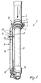
- a damper member is indicated overall by 1 and comprises a sleeve 2 associated with the motorcycle frame (not shown), and a rod 3 which can move relative to said sleeve and is associated with the vehicle front wheel (not shown) in known manner.
- the sleeve 2 carries a split ring member 6 which can be clamped onto the sleeve by usual screws cooperating with projections 7.
- the ring member 6 carries a hook-shaped element 8 arranged to cooperate with a device 9 for locking the damper member in a compressed position.
- said device 9 is a member 10 positioned to the front of the rod 3 and acting substantially as a rod guard.
- This guard is of arched shape and has an end 12 to be fixed onto the rod at its extremity 13, ie to the foot of the fork.
- the rod guard 10 has a plurality of through holes 15, any of which can be made to cooperate with the hook-shaped element 8 of the ring member 6 fixed on the sleeve 2 so that on starting the motorcycle the member 1 is maintained in a compressed position or in one of a plurality of such positions as allowed by the plurality of holes 15 provided at different heights in the rod guard 10.
- the device of the invention is to be operated on the motorcycle.
- the member 1 Before starting the motorcycle, for example during a competition, the member 1 is compressed (but not totally) by the driver in any known manner. While maintaining pressure on the member 1, the rod guard 10 is coupled to the ring member 6 by inserting the element or hook 8 into a hole 15 in the rod guard. If pressure on the member 1 is now released, it will remain in the compressed position because of the cooperation between the hook 8 and said hole 15.
- the rod guard 10 can be twisted (arrow F of Figure 1).
- the compressed position of the member 1 enables the engine power to be totally used for moving the motorcycle.
- the vehicle barycentre being shifted towards the front end of the vehicle. This enables the inertia on the rear wheel to be reduced, with reduction in the duration of contact between the front wheel and the ground, resulting in immediate forward movement of the starting motorcycle.
- the rod guard 10 After movement has commenced, when the damper member is further compressed for example by impact with the ground after a jump (in the case of endurance racing) or after braking, the rod guard 10 unhooks automatically from the hook 8 to release the sleeve 2 of the rod 3 and allow the damper 1 to operate normally. This is due to the dimensions of the hole 15 and to the elasticity of the rod guard, which tends to return from its twisted position to its rest position (arrow G of Figure 1).
- Figures 5 and 6 show a different device 9 applied to the "hydraulic circuit" of the damper 1.
- this latter comprises a cylindrical element 20 within the rod 3 and immersed in the lubricant liquid present therein, said cylindrical element having an upper wall 21 and a lower wall 22 which are connected together by a lateral wall 23.
- apertures 24 connecting the inner space 25 of the element 20 to the inner space 26 of the rod 3.
- the inner space 25 of the element 20 is divided into two chambers 25A and 25B by a member 28 associated with a shaft 30 which penetrates into the head 31 of the fork and emerges above it where it is connected to a disc 32.
- This disc has a portion 32A of cup shape with a skirt 34 lowerly cooperating with a pawl 35 provided with a wedge-shaped end 36 having a step 37, and a T-shaped second end 38 with which there cooperates a spring 39 inserted in a seat 40 in the head 31.
- the step 37 is arranged to cooperate with the skirt 34.
- the member 28 comprises in known manner a plurality of through holes 40A to be closed by blade members 41 and 42.
- the blade member 41 opens the holes 40A towards the chamber 25A (to hence allow the lubricant to pass from the chamber 25B to the chamber 25A) when the damper 1 is being compressed (as shown in Figure 5)
- the blade member 42 opens the holes 40A towards the chamber 25B (to connect it to the chamber 25A) when the damper 1 is extending.
- a closure element 50 for the holes 40A which cooperates with the blade member 42 to prevent lubricant passing from the chamber 25B to the chamber 25A and hence prevent the damper (and the fork) extending.
- This element defining the device 9 of the invention, is associated with the free end 51 of the shaft 30 and comprises a ring member 52 arranged to cooperate with the blade member 41.
- a compression spring 53 is interposed between the ring member 52 and a cup element 54 fixed to the end 51 of the shaft 30.
- the driver loads the damper 1 by compressing it as previously described in relation to the embodiment of Figures 1 to 4.
- the fluid in the chamber 25A passes through the holes 40A and penetrates, in known manner, into the chamber 25B by overcoming the closure force of the blade member 42.
- the driver raises (arrow W of Figure 6) the shaft 30 by moving it against the spring 53, and presses the pawl 35 against the spring 39 so as to bring its wedge-shaped end 36 below the cup 32A and engage the skirt 34 of this latter with the step 37.
- the element 50 approaches the blade member 42 and presses it against the member 28.
- the ring member 52 is brought into contact with the blade member 42 and prevents its movement.
- the pawl 35 of Figures 5 and 6 can be released automatically following the next further compression movement of the damper 1, such movement occurring for example when the fork undergoes its first impact after starting.
- the pawl 35 can also be released as the result of a hydraulic thrust exerted on the member 28 following the first impact after starting, which by compressing the spring 53 lifts the disc 32 and the cup 34, to release the pawl 35.
Landscapes
- Engineering & Computer Science (AREA)
- General Engineering & Computer Science (AREA)
- Mechanical Engineering (AREA)
- Fluid-Damping Devices (AREA)
- Axle Suspensions And Sidecars For Cycles (AREA)
Applications Claiming Priority (2)
| Application Number | Priority Date | Filing Date | Title |
|---|---|---|---|
| ITMI981436 | 1998-06-23 | ||
| IT1998MI001436A IT1301787B1 (it) | 1998-06-23 | 1998-06-23 | Dispositivo antisollevamento di una forcella anteriore di unamotocicletta |
Publications (2)
| Publication Number | Publication Date |
|---|---|
| EP0967143A2 true EP0967143A2 (fr) | 1999-12-29 |
| EP0967143A3 EP0967143A3 (fr) | 2000-10-04 |
Family
ID=11380306
Family Applications (1)
| Application Number | Title | Priority Date | Filing Date |
|---|---|---|---|
| EP99111765A Withdrawn EP0967143A3 (fr) | 1998-06-23 | 1999-06-18 | Dispositif anti-soulèvement pour fourche avant de motocyclette |
Country Status (2)
| Country | Link |
|---|---|
| EP (1) | EP0967143A3 (fr) |
| IT (1) | IT1301787B1 (fr) |
Cited By (3)
| Publication number | Priority date | Publication date | Assignee | Title |
|---|---|---|---|---|
| EP1498636A3 (fr) * | 2003-07-18 | 2005-06-08 | Dr.Ing. h.c.F. Porsche Aktiengesellschaft | Dispositif de bloquage d'une suspension |
| FR3026059A1 (fr) * | 2014-09-23 | 2016-03-25 | Peugeot Citroen Automobiles Sa | Amortisseur avec crochets de fixation d'une sangle de montage |
| WO2016055706A1 (fr) * | 2014-10-09 | 2016-04-14 | Peugeot Citroen Automobiles Sa | Système de protection pour amortisseur hydraulique comportant des découpes pour une sangle de compression |
Family Cites Families (3)
| Publication number | Priority date | Publication date | Assignee | Title |
|---|---|---|---|---|
| JPS59223583A (ja) * | 1983-06-03 | 1984-12-15 | 本田技研工業株式会社 | 自動二・三輪車 |
| US4735276A (en) * | 1985-08-22 | 1988-04-05 | Burton John E | Apparatus for front suspension of motorcycle |
| DE4429562C2 (de) * | 1994-08-19 | 1998-03-19 | Stefan Maier | Hydraulischer Schwingungsdämpfer für das gefederte Vorderrad eines Fahrrads |
-
1998
- 1998-06-23 IT IT1998MI001436A patent/IT1301787B1/it active IP Right Grant
-
1999
- 1999-06-18 EP EP99111765A patent/EP0967143A3/fr not_active Withdrawn
Non-Patent Citations (1)
| Title |
|---|
| None |
Cited By (4)
| Publication number | Priority date | Publication date | Assignee | Title |
|---|---|---|---|---|
| EP1498636A3 (fr) * | 2003-07-18 | 2005-06-08 | Dr.Ing. h.c.F. Porsche Aktiengesellschaft | Dispositif de bloquage d'une suspension |
| FR3026059A1 (fr) * | 2014-09-23 | 2016-03-25 | Peugeot Citroen Automobiles Sa | Amortisseur avec crochets de fixation d'une sangle de montage |
| WO2016055706A1 (fr) * | 2014-10-09 | 2016-04-14 | Peugeot Citroen Automobiles Sa | Système de protection pour amortisseur hydraulique comportant des découpes pour une sangle de compression |
| FR3027083A1 (fr) * | 2014-10-09 | 2016-04-15 | Peugeot Citroen Automobiles Sa | Systeme de protection pour amortisseur hydraulique comportant des decoupes pour une sangle de compression |
Also Published As
| Publication number | Publication date |
|---|---|
| ITMI981436A1 (it) | 1999-12-23 |
| IT1301787B1 (it) | 2000-07-07 |
| EP0967143A3 (fr) | 2000-10-04 |
Similar Documents
| Publication | Publication Date | Title |
|---|---|---|
| EP0967143A2 (fr) | Dispositif anti-soulèvement pour fourche avant de motocyclette | |
| FR2561188A1 (fr) | Servomecanisme de freinage hydraulique pour vehicule automobile | |
| JP2000508414A (ja) | 環状密封部材 | |
| KR20000064689A (ko) | 주브레이크실린더 | |
| US5009581A (en) | Fluid accumulator for anti-skid brakes | |
| KR970003889Y1 (ko) | 자동차 유압 클러치의 마스터 실린더 | |
| KR100398436B1 (ko) | 카매트 고정장치 | |
| KR200143963Y1 (ko) | 클러치 마스터 실린더의 피스톤구조 | |
| EP0705787B1 (fr) | Dispositif d'entretien pour la maintenance de chariots | |
| KR950006985Y1 (ko) | 자동차 유압 클러치의 클러치유 급속 귀환장치 | |
| KR19980035735A (ko) | 브레이크오일 순환 및 베이퍼록(vaporlock) 방지 장치 | |
| JPH0313375Y2 (fr) | ||
| KR920006440B1 (ko) | 자동차 충돌시의 자동급제동장치 | |
| KR0113376Y1 (ko) | 자동차의 주차브레이크 | |
| KR890005321B1 (ko) | 자동차 클러치페달을 이용한 전,후진 방지 유압 브레이크장치 | |
| KR900007462Y1 (ko) | 자동차의 반자동 클러치장치 | |
| KR200179261Y1 (ko) | 페달식 주차브레이크장치 | |
| JPS5856429Y2 (ja) | クラツチアシスタ | |
| KR100199427B1 (ko) | 엔진 rpm 오버런(over run) 방지 장치 | |
| KR200146869Y1 (ko) | 파킹 브레이크 자동조작장치 | |
| KR19980038277A (ko) | 자동차의 브레이크 오일 냉각장치 | |
| KR0130524Y1 (ko) | 자동차 미끄러짐 방지용 유압식 제어장치 | |
| KR960003808Y1 (ko) | 자동차의 주차 안전장치 | |
| KR0118768Y1 (ko) | 액셀 페달 | |
| KR19990028224U (ko) | 제동상태 출발 방지장치 |
Legal Events
| Date | Code | Title | Description |
|---|---|---|---|
| PUAI | Public reference made under article 153(3) epc to a published international application that has entered the european phase |
Free format text: ORIGINAL CODE: 0009012 |
|
| AK | Designated contracting states |
Kind code of ref document: A2 Designated state(s): AT BE CH CY DE DK ES FI FR GB GR IE IT LI LU MC NL PT SE |
|
| AX | Request for extension of the european patent |
Free format text: AL;LT;LV;MK;RO;SI |
|
| RAP1 | Party data changed (applicant data changed or rights of an application transferred) |
Owner name: MV AGUSTA MOTOR S.P.A. |
|
| PUAL | Search report despatched |
Free format text: ORIGINAL CODE: 0009013 |
|
| AK | Designated contracting states |
Kind code of ref document: A3 Designated state(s): AT BE CH CY DE DK ES FI FR GB GR IE IT LI LU MC NL PT SE |
|
| AX | Request for extension of the european patent |
Free format text: AL;LT;LV;MK;RO;SI |
|
| AKX | Designation fees paid | ||
| REG | Reference to a national code |
Ref country code: DE Ref legal event code: 8566 |
|
| STAA | Information on the status of an ep patent application or granted ep patent |
Free format text: STATUS: THE APPLICATION IS DEEMED TO BE WITHDRAWN |
|
| 18D | Application deemed to be withdrawn |
Effective date: 20010405 |