EP0967190B1 - Procédé de fabrication de fibres courtes revêtues - Google Patents
Procédé de fabrication de fibres courtes revêtues Download PDFInfo
- Publication number
- EP0967190B1 EP0967190B1 EP99112209A EP99112209A EP0967190B1 EP 0967190 B1 EP0967190 B1 EP 0967190B1 EP 99112209 A EP99112209 A EP 99112209A EP 99112209 A EP99112209 A EP 99112209A EP 0967190 B1 EP0967190 B1 EP 0967190B1
- Authority
- EP
- European Patent Office
- Prior art keywords
- coated
- fibres
- coating
- short
- graduated
- Prior art date
- Legal status (The legal status is an assumption and is not a legal conclusion. Google has not performed a legal analysis and makes no representation as to the accuracy of the status listed.)
- Expired - Lifetime
Links
- 239000000835 fiber Substances 0.000 title claims description 136
- 238000000034 method Methods 0.000 title claims description 29
- 230000008569 process Effects 0.000 title description 4
- 239000011248 coating agent Substances 0.000 claims description 42
- 238000000576 coating method Methods 0.000 claims description 41
- HBMJWWWQQXIZIP-UHFFFAOYSA-N silicon carbide Chemical compound [Si+]#[C-] HBMJWWWQQXIZIP-UHFFFAOYSA-N 0.000 claims description 29
- 229910010271 silicon carbide Inorganic materials 0.000 claims description 29
- 239000002131 composite material Substances 0.000 claims description 20
- 239000011159 matrix material Substances 0.000 claims description 16
- ATJFFYVFTNAWJD-UHFFFAOYSA-N Tin Chemical compound [Sn] ATJFFYVFTNAWJD-UHFFFAOYSA-N 0.000 claims description 11
- 239000011156 metal matrix composite Substances 0.000 claims description 9
- OKTJSMMVPCPJKN-UHFFFAOYSA-N Carbon Chemical compound [C] OKTJSMMVPCPJKN-UHFFFAOYSA-N 0.000 claims description 7
- 229910052799 carbon Inorganic materials 0.000 claims description 7
- 239000000126 substance Substances 0.000 claims description 7
- 230000008021 deposition Effects 0.000 claims description 6
- VNWKTOKETHGBQD-UHFFFAOYSA-N methane Chemical compound C VNWKTOKETHGBQD-UHFFFAOYSA-N 0.000 claims description 6
- 238000005520 cutting process Methods 0.000 claims description 5
- IJGRMHOSHXDMSA-UHFFFAOYSA-N Atomic nitrogen Chemical compound N#N IJGRMHOSHXDMSA-UHFFFAOYSA-N 0.000 claims description 4
- UFHFLCQGNIYNRP-UHFFFAOYSA-N Hydrogen Chemical compound [H][H] UFHFLCQGNIYNRP-UHFFFAOYSA-N 0.000 claims description 4
- 239000001257 hydrogen Substances 0.000 claims description 4
- 229910052739 hydrogen Inorganic materials 0.000 claims description 4
- 239000004033 plastic Substances 0.000 claims description 4
- 229920003023 plastic Polymers 0.000 claims description 4
- 239000011226 reinforced ceramic Substances 0.000 claims description 3
- 239000005055 methyl trichlorosilane Substances 0.000 claims description 2
- JLUFWMXJHAVVNN-UHFFFAOYSA-N methyltrichlorosilane Chemical compound C[Si](Cl)(Cl)Cl JLUFWMXJHAVVNN-UHFFFAOYSA-N 0.000 claims description 2
- 229910052757 nitrogen Inorganic materials 0.000 claims description 2
- XJDNKRIXUMDJCW-UHFFFAOYSA-J titanium tetrachloride Chemical compound Cl[Ti](Cl)(Cl)Cl XJDNKRIXUMDJCW-UHFFFAOYSA-J 0.000 claims description 2
- CYKMNKXPYXUVPR-UHFFFAOYSA-N [C].[Ti] Chemical compound [C].[Ti] CYKMNKXPYXUVPR-UHFFFAOYSA-N 0.000 claims 3
- 239000007792 gaseous phase Substances 0.000 claims 2
- 239000011208 reinforced composite material Substances 0.000 claims 1
- 239000010410 layer Substances 0.000 description 24
- 239000012495 reaction gas Substances 0.000 description 14
- 239000000463 material Substances 0.000 description 12
- 239000000203 mixture Substances 0.000 description 11
- 238000004519 manufacturing process Methods 0.000 description 10
- 229920000049 Carbon (fiber) Polymers 0.000 description 9
- 239000004917 carbon fiber Substances 0.000 description 9
- 238000006243 chemical reaction Methods 0.000 description 8
- 239000007789 gas Substances 0.000 description 7
- 238000009990 desizing Methods 0.000 description 6
- RTAQQCXQSZGOHL-UHFFFAOYSA-N Titanium Chemical compound [Ti] RTAQQCXQSZGOHL-UHFFFAOYSA-N 0.000 description 5
- 239000000919 ceramic Substances 0.000 description 5
- 239000003733 fiber-reinforced composite Substances 0.000 description 5
- 239000010936 titanium Substances 0.000 description 5
- 229910052719 titanium Inorganic materials 0.000 description 5
- 238000000151 deposition Methods 0.000 description 4
- 238000010438 heat treatment Methods 0.000 description 4
- NRTOMJZYCJJWKI-UHFFFAOYSA-N Titanium nitride Chemical compound [Ti]#N NRTOMJZYCJJWKI-UHFFFAOYSA-N 0.000 description 3
- 239000000853 adhesive Substances 0.000 description 3
- 230000001070 adhesive effect Effects 0.000 description 3
- 239000011241 protective layer Substances 0.000 description 3
- 238000007789 sealing Methods 0.000 description 3
- 238000000926 separation method Methods 0.000 description 3
- 230000035939 shock Effects 0.000 description 3
- 238000003860 storage Methods 0.000 description 3
- 230000007704 transition Effects 0.000 description 3
- XUIMIQQOPSSXEZ-UHFFFAOYSA-N Silicon Chemical compound [Si] XUIMIQQOPSSXEZ-UHFFFAOYSA-N 0.000 description 2
- SGPGESCZOCHFCL-UHFFFAOYSA-N Tilisolol hydrochloride Chemical compound [Cl-].C1=CC=C2C(=O)N(C)C=C(OCC(O)C[NH2+]C(C)(C)C)C2=C1 SGPGESCZOCHFCL-UHFFFAOYSA-N 0.000 description 2
- 230000004888 barrier function Effects 0.000 description 2
- 230000008859 change Effects 0.000 description 2
- 238000011161 development Methods 0.000 description 2
- 230000018109 developmental process Effects 0.000 description 2
- 238000010586 diagram Methods 0.000 description 2
- 238000009792 diffusion process Methods 0.000 description 2
- 230000006698 induction Effects 0.000 description 2
- 239000011261 inert gas Substances 0.000 description 2
- 238000001764 infiltration Methods 0.000 description 2
- 230000008595 infiltration Effects 0.000 description 2
- 238000000626 liquid-phase infiltration Methods 0.000 description 2
- 229910052751 metal Inorganic materials 0.000 description 2
- 239000002184 metal Substances 0.000 description 2
- 238000000879 optical micrograph Methods 0.000 description 2
- 230000002787 reinforcement Effects 0.000 description 2
- 238000001878 scanning electron micrograph Methods 0.000 description 2
- 229910052710 silicon Inorganic materials 0.000 description 2
- 239000010703 silicon Substances 0.000 description 2
- 239000010935 stainless steel Substances 0.000 description 2
- 229910001220 stainless steel Inorganic materials 0.000 description 2
- 238000002604 ultrasonography Methods 0.000 description 2
- 229910018072 Al 2 O 3 Inorganic materials 0.000 description 1
- 229910000838 Al alloy Inorganic materials 0.000 description 1
- 229920002430 Fibre-reinforced plastic Polymers 0.000 description 1
- 229910000861 Mg alloy Inorganic materials 0.000 description 1
- 229910000831 Steel Inorganic materials 0.000 description 1
- 239000004809 Teflon Substances 0.000 description 1
- 229920006362 Teflon® Polymers 0.000 description 1
- 230000009471 action Effects 0.000 description 1
- 230000001464 adherent effect Effects 0.000 description 1
- 238000009960 carding Methods 0.000 description 1
- 238000005229 chemical vapour deposition Methods 0.000 description 1
- 239000011247 coating layer Substances 0.000 description 1
- 230000008878 coupling Effects 0.000 description 1
- 238000010168 coupling process Methods 0.000 description 1
- 238000005859 coupling reaction Methods 0.000 description 1
- 238000003618 dip coating Methods 0.000 description 1
- 230000000694 effects Effects 0.000 description 1
- 238000005516 engineering process Methods 0.000 description 1
- 239000011151 fibre-reinforced plastic Substances 0.000 description 1
- 238000007654 immersion Methods 0.000 description 1
- 230000006872 improvement Effects 0.000 description 1
- 238000007373 indentation Methods 0.000 description 1
- 230000003647 oxidation Effects 0.000 description 1
- 238000007254 oxidation reaction Methods 0.000 description 1
- 230000001590 oxidative effect Effects 0.000 description 1
- 239000011224 oxide ceramic Substances 0.000 description 1
- 229910052574 oxide ceramic Inorganic materials 0.000 description 1
- TWNQGVIAIRXVLR-UHFFFAOYSA-N oxo(oxoalumanyloxy)alumane Chemical compound O=[Al]O[Al]=O TWNQGVIAIRXVLR-UHFFFAOYSA-N 0.000 description 1
- 238000013001 point bending Methods 0.000 description 1
- 239000010453 quartz Substances 0.000 description 1
- 230000005855 radiation Effects 0.000 description 1
- VYPSYNLAJGMNEJ-UHFFFAOYSA-N silicon dioxide Inorganic materials O=[Si]=O VYPSYNLAJGMNEJ-UHFFFAOYSA-N 0.000 description 1
- 239000010959 steel Substances 0.000 description 1
- 239000000758 substrate Substances 0.000 description 1
- 239000000725 suspension Substances 0.000 description 1
- 239000004753 textile Substances 0.000 description 1
- MTPVUVINMAGMJL-UHFFFAOYSA-N trimethyl(1,1,2,2,2-pentafluoroethyl)silane Chemical compound C[Si](C)(C)C(F)(F)C(F)(F)F MTPVUVINMAGMJL-UHFFFAOYSA-N 0.000 description 1
- 210000001170 unmyelinated nerve fiber Anatomy 0.000 description 1
Images


Classifications
-
- C—CHEMISTRY; METALLURGY
- C04—CEMENTS; CONCRETE; ARTIFICIAL STONE; CERAMICS; REFRACTORIES
- C04B—LIME, MAGNESIA; SLAG; CEMENTS; COMPOSITIONS THEREOF, e.g. MORTARS, CONCRETE OR LIKE BUILDING MATERIALS; ARTIFICIAL STONE; CERAMICS; REFRACTORIES; TREATMENT OF NATURAL STONE
- C04B35/00—Shaped ceramic products characterised by their composition; Ceramics compositions; Processing powders of inorganic compounds preparatory to the manufacturing of ceramic products
- C04B35/622—Forming processes; Processing powders of inorganic compounds preparatory to the manufacturing of ceramic products
- C04B35/626—Preparing or treating the powders individually or as batches ; preparing or treating macroscopic reinforcing agents for ceramic products, e.g. fibres; mechanical aspects section B
- C04B35/628—Coating the powders or the macroscopic reinforcing agents
- C04B35/62844—Coating fibres
- C04B35/62857—Coating fibres with non-oxide ceramics
- C04B35/6286—Carbides
-
- C—CHEMISTRY; METALLURGY
- C04—CEMENTS; CONCRETE; ARTIFICIAL STONE; CERAMICS; REFRACTORIES
- C04B—LIME, MAGNESIA; SLAG; CEMENTS; COMPOSITIONS THEREOF, e.g. MORTARS, CONCRETE OR LIKE BUILDING MATERIALS; ARTIFICIAL STONE; CERAMICS; REFRACTORIES; TREATMENT OF NATURAL STONE
- C04B35/00—Shaped ceramic products characterised by their composition; Ceramics compositions; Processing powders of inorganic compounds preparatory to the manufacturing of ceramic products
- C04B35/622—Forming processes; Processing powders of inorganic compounds preparatory to the manufacturing of ceramic products
- C04B35/626—Preparing or treating the powders individually or as batches ; preparing or treating macroscopic reinforcing agents for ceramic products, e.g. fibres; mechanical aspects section B
- C04B35/628—Coating the powders or the macroscopic reinforcing agents
- C04B35/62844—Coating fibres
- C04B35/62857—Coating fibres with non-oxide ceramics
- C04B35/6286—Carbides
- C04B35/62863—Silicon carbide
-
- C—CHEMISTRY; METALLURGY
- C04—CEMENTS; CONCRETE; ARTIFICIAL STONE; CERAMICS; REFRACTORIES
- C04B—LIME, MAGNESIA; SLAG; CEMENTS; COMPOSITIONS THEREOF, e.g. MORTARS, CONCRETE OR LIKE BUILDING MATERIALS; ARTIFICIAL STONE; CERAMICS; REFRACTORIES; TREATMENT OF NATURAL STONE
- C04B35/00—Shaped ceramic products characterised by their composition; Ceramics compositions; Processing powders of inorganic compounds preparatory to the manufacturing of ceramic products
- C04B35/622—Forming processes; Processing powders of inorganic compounds preparatory to the manufacturing of ceramic products
- C04B35/626—Preparing or treating the powders individually or as batches ; preparing or treating macroscopic reinforcing agents for ceramic products, e.g. fibres; mechanical aspects section B
- C04B35/628—Coating the powders or the macroscopic reinforcing agents
- C04B35/62844—Coating fibres
- C04B35/62857—Coating fibres with non-oxide ceramics
- C04B35/62865—Nitrides
-
- C—CHEMISTRY; METALLURGY
- C04—CEMENTS; CONCRETE; ARTIFICIAL STONE; CERAMICS; REFRACTORIES
- C04B—LIME, MAGNESIA; SLAG; CEMENTS; COMPOSITIONS THEREOF, e.g. MORTARS, CONCRETE OR LIKE BUILDING MATERIALS; ARTIFICIAL STONE; CERAMICS; REFRACTORIES; TREATMENT OF NATURAL STONE
- C04B35/00—Shaped ceramic products characterised by their composition; Ceramics compositions; Processing powders of inorganic compounds preparatory to the manufacturing of ceramic products
- C04B35/622—Forming processes; Processing powders of inorganic compounds preparatory to the manufacturing of ceramic products
- C04B35/626—Preparing or treating the powders individually or as batches ; preparing or treating macroscopic reinforcing agents for ceramic products, e.g. fibres; mechanical aspects section B
- C04B35/628—Coating the powders or the macroscopic reinforcing agents
- C04B35/62844—Coating fibres
- C04B35/62857—Coating fibres with non-oxide ceramics
- C04B35/62873—Carbon
-
- C—CHEMISTRY; METALLURGY
- C04—CEMENTS; CONCRETE; ARTIFICIAL STONE; CERAMICS; REFRACTORIES
- C04B—LIME, MAGNESIA; SLAG; CEMENTS; COMPOSITIONS THEREOF, e.g. MORTARS, CONCRETE OR LIKE BUILDING MATERIALS; ARTIFICIAL STONE; CERAMICS; REFRACTORIES; TREATMENT OF NATURAL STONE
- C04B35/00—Shaped ceramic products characterised by their composition; Ceramics compositions; Processing powders of inorganic compounds preparatory to the manufacturing of ceramic products
- C04B35/622—Forming processes; Processing powders of inorganic compounds preparatory to the manufacturing of ceramic products
- C04B35/626—Preparing or treating the powders individually or as batches ; preparing or treating macroscopic reinforcing agents for ceramic products, e.g. fibres; mechanical aspects section B
- C04B35/628—Coating the powders or the macroscopic reinforcing agents
- C04B35/62884—Coating the powders or the macroscopic reinforcing agents by gas phase techniques
-
- C—CHEMISTRY; METALLURGY
- C04—CEMENTS; CONCRETE; ARTIFICIAL STONE; CERAMICS; REFRACTORIES
- C04B—LIME, MAGNESIA; SLAG; CEMENTS; COMPOSITIONS THEREOF, e.g. MORTARS, CONCRETE OR LIKE BUILDING MATERIALS; ARTIFICIAL STONE; CERAMICS; REFRACTORIES; TREATMENT OF NATURAL STONE
- C04B35/00—Shaped ceramic products characterised by their composition; Ceramics compositions; Processing powders of inorganic compounds preparatory to the manufacturing of ceramic products
- C04B35/622—Forming processes; Processing powders of inorganic compounds preparatory to the manufacturing of ceramic products
- C04B35/626—Preparing or treating the powders individually or as batches ; preparing or treating macroscopic reinforcing agents for ceramic products, e.g. fibres; mechanical aspects section B
- C04B35/628—Coating the powders or the macroscopic reinforcing agents
- C04B35/62897—Coatings characterised by their thickness
-
- C—CHEMISTRY; METALLURGY
- C04—CEMENTS; CONCRETE; ARTIFICIAL STONE; CERAMICS; REFRACTORIES
- C04B—LIME, MAGNESIA; SLAG; CEMENTS; COMPOSITIONS THEREOF, e.g. MORTARS, CONCRETE OR LIKE BUILDING MATERIALS; ARTIFICIAL STONE; CERAMICS; REFRACTORIES; TREATMENT OF NATURAL STONE
- C04B35/00—Shaped ceramic products characterised by their composition; Ceramics compositions; Processing powders of inorganic compounds preparatory to the manufacturing of ceramic products
- C04B35/71—Ceramic products containing macroscopic reinforcing agents
- C04B35/78—Ceramic products containing macroscopic reinforcing agents containing non-metallic materials
- C04B35/80—Fibres, filaments, whiskers, platelets, or the like
-
- C—CHEMISTRY; METALLURGY
- C04—CEMENTS; CONCRETE; ARTIFICIAL STONE; CERAMICS; REFRACTORIES
- C04B—LIME, MAGNESIA; SLAG; CEMENTS; COMPOSITIONS THEREOF, e.g. MORTARS, CONCRETE OR LIKE BUILDING MATERIALS; ARTIFICIAL STONE; CERAMICS; REFRACTORIES; TREATMENT OF NATURAL STONE
- C04B41/00—After-treatment of mortars, concrete, artificial stone or ceramics; Treatment of natural stone
- C04B41/009—After-treatment of mortars, concrete, artificial stone or ceramics; Treatment of natural stone characterised by the material treated
-
- C—CHEMISTRY; METALLURGY
- C04—CEMENTS; CONCRETE; ARTIFICIAL STONE; CERAMICS; REFRACTORIES
- C04B—LIME, MAGNESIA; SLAG; CEMENTS; COMPOSITIONS THEREOF, e.g. MORTARS, CONCRETE OR LIKE BUILDING MATERIALS; ARTIFICIAL STONE; CERAMICS; REFRACTORIES; TREATMENT OF NATURAL STONE
- C04B41/00—After-treatment of mortars, concrete, artificial stone or ceramics; Treatment of natural stone
- C04B41/45—Coating or impregnating, e.g. injection in masonry, partial coating of green or fired ceramics, organic coating compositions for adhering together two concrete elements
- C04B41/4584—Coating or impregnating of particulate or fibrous ceramic material
-
- C—CHEMISTRY; METALLURGY
- C22—METALLURGY; FERROUS OR NON-FERROUS ALLOYS; TREATMENT OF ALLOYS OR NON-FERROUS METALS
- C22C—ALLOYS
- C22C47/00—Making alloys containing metallic or non-metallic fibres or filaments
- C22C47/02—Pretreatment of the fibres or filaments
- C22C47/04—Pretreatment of the fibres or filaments by coating, e.g. with a protective or activated covering
-
- C—CHEMISTRY; METALLURGY
- C22—METALLURGY; FERROUS OR NON-FERROUS ALLOYS; TREATMENT OF ALLOYS OR NON-FERROUS METALS
- C22C—ALLOYS
- C22C47/00—Making alloys containing metallic or non-metallic fibres or filaments
- C22C47/08—Making alloys containing metallic or non-metallic fibres or filaments by contacting the fibres or filaments with molten metal, e.g. by infiltrating the fibres or filaments placed in a mould
- C22C47/12—Infiltration or casting under mechanical pressure
-
- C—CHEMISTRY; METALLURGY
- C22—METALLURGY; FERROUS OR NON-FERROUS ALLOYS; TREATMENT OF ALLOYS OR NON-FERROUS METALS
- C22C—ALLOYS
- C22C49/00—Alloys containing metallic or non-metallic fibres or filaments
- C22C49/02—Alloys containing metallic or non-metallic fibres or filaments characterised by the matrix material
- C22C49/04—Light metals
- C22C49/06—Aluminium
-
- C—CHEMISTRY; METALLURGY
- C22—METALLURGY; FERROUS OR NON-FERROUS ALLOYS; TREATMENT OF ALLOYS OR NON-FERROUS METALS
- C22C—ALLOYS
- C22C49/00—Alloys containing metallic or non-metallic fibres or filaments
- C22C49/14—Alloys containing metallic or non-metallic fibres or filaments characterised by the fibres or filaments
-
- C—CHEMISTRY; METALLURGY
- C23—COATING METALLIC MATERIAL; COATING MATERIAL WITH METALLIC MATERIAL; CHEMICAL SURFACE TREATMENT; DIFFUSION TREATMENT OF METALLIC MATERIAL; COATING BY VACUUM EVAPORATION, BY SPUTTERING, BY ION IMPLANTATION OR BY CHEMICAL VAPOUR DEPOSITION, IN GENERAL; INHIBITING CORROSION OF METALLIC MATERIAL OR INCRUSTATION IN GENERAL
- C23C—COATING METALLIC MATERIAL; COATING MATERIAL WITH METALLIC MATERIAL; SURFACE TREATMENT OF METALLIC MATERIAL BY DIFFUSION INTO THE SURFACE, BY CHEMICAL CONVERSION OR SUBSTITUTION; COATING BY VACUUM EVAPORATION, BY SPUTTERING, BY ION IMPLANTATION OR BY CHEMICAL VAPOUR DEPOSITION, IN GENERAL
- C23C16/00—Chemical coating by decomposition of gaseous compounds, without leaving reaction products of surface material in the coating, i.e. chemical vapour deposition [CVD] processes
- C23C16/02—Pretreatment of the material to be coated
- C23C16/0209—Pretreatment of the material to be coated by heating
-
- C—CHEMISTRY; METALLURGY
- C23—COATING METALLIC MATERIAL; COATING MATERIAL WITH METALLIC MATERIAL; CHEMICAL SURFACE TREATMENT; DIFFUSION TREATMENT OF METALLIC MATERIAL; COATING BY VACUUM EVAPORATION, BY SPUTTERING, BY ION IMPLANTATION OR BY CHEMICAL VAPOUR DEPOSITION, IN GENERAL; INHIBITING CORROSION OF METALLIC MATERIAL OR INCRUSTATION IN GENERAL
- C23C—COATING METALLIC MATERIAL; COATING MATERIAL WITH METALLIC MATERIAL; SURFACE TREATMENT OF METALLIC MATERIAL BY DIFFUSION INTO THE SURFACE, BY CHEMICAL CONVERSION OR SUBSTITUTION; COATING BY VACUUM EVAPORATION, BY SPUTTERING, BY ION IMPLANTATION OR BY CHEMICAL VAPOUR DEPOSITION, IN GENERAL
- C23C16/00—Chemical coating by decomposition of gaseous compounds, without leaving reaction products of surface material in the coating, i.e. chemical vapour deposition [CVD] processes
- C23C16/44—Chemical coating by decomposition of gaseous compounds, without leaving reaction products of surface material in the coating, i.e. chemical vapour deposition [CVD] processes characterised by the method of coating
- C23C16/54—Apparatus specially adapted for continuous coating
- C23C16/545—Apparatus specially adapted for continuous coating for coating elongated substrates
-
- B—PERFORMING OPERATIONS; TRANSPORTING
- B22—CASTING; POWDER METALLURGY
- B22F—WORKING METALLIC POWDER; MANUFACTURE OF ARTICLES FROM METALLIC POWDER; MAKING METALLIC POWDER; APPARATUS OR DEVICES SPECIALLY ADAPTED FOR METALLIC POWDER
- B22F2999/00—Aspects linked to processes or compositions used in powder metallurgy
-
- C—CHEMISTRY; METALLURGY
- C04—CEMENTS; CONCRETE; ARTIFICIAL STONE; CERAMICS; REFRACTORIES
- C04B—LIME, MAGNESIA; SLAG; CEMENTS; COMPOSITIONS THEREOF, e.g. MORTARS, CONCRETE OR LIKE BUILDING MATERIALS; ARTIFICIAL STONE; CERAMICS; REFRACTORIES; TREATMENT OF NATURAL STONE
- C04B2111/00—Mortars, concrete or artificial stone or mixtures to prepare them, characterised by specific function, property or use
- C04B2111/00241—Physical properties of the materials not provided for elsewhere in C04B2111/00
- C04B2111/00405—Materials with a gradually increasing or decreasing concentration of ingredients or property from one layer to another
-
- C—CHEMISTRY; METALLURGY
- C04—CEMENTS; CONCRETE; ARTIFICIAL STONE; CERAMICS; REFRACTORIES
- C04B—LIME, MAGNESIA; SLAG; CEMENTS; COMPOSITIONS THEREOF, e.g. MORTARS, CONCRETE OR LIKE BUILDING MATERIALS; ARTIFICIAL STONE; CERAMICS; REFRACTORIES; TREATMENT OF NATURAL STONE
- C04B2235/00—Aspects relating to ceramic starting mixtures or sintered ceramic products
- C04B2235/02—Composition of constituents of the starting material or of secondary phases of the final product
- C04B2235/50—Constituents or additives of the starting mixture chosen for their shape or used because of their shape or their physical appearance
- C04B2235/52—Constituents or additives characterised by their shapes
- C04B2235/5208—Fibers
- C04B2235/5216—Inorganic
- C04B2235/524—Non-oxidic, e.g. borides, carbides, silicides or nitrides
- C04B2235/5248—Carbon, e.g. graphite
-
- C—CHEMISTRY; METALLURGY
- C04—CEMENTS; CONCRETE; ARTIFICIAL STONE; CERAMICS; REFRACTORIES
- C04B—LIME, MAGNESIA; SLAG; CEMENTS; COMPOSITIONS THEREOF, e.g. MORTARS, CONCRETE OR LIKE BUILDING MATERIALS; ARTIFICIAL STONE; CERAMICS; REFRACTORIES; TREATMENT OF NATURAL STONE
- C04B2235/00—Aspects relating to ceramic starting mixtures or sintered ceramic products
- C04B2235/02—Composition of constituents of the starting material or of secondary phases of the final product
- C04B2235/50—Constituents or additives of the starting mixture chosen for their shape or used because of their shape or their physical appearance
- C04B2235/52—Constituents or additives characterised by their shapes
- C04B2235/5208—Fibers
- C04B2235/526—Fibers characterised by the length of the fibers
-
- C—CHEMISTRY; METALLURGY
- C04—CEMENTS; CONCRETE; ARTIFICIAL STONE; CERAMICS; REFRACTORIES
- C04B—LIME, MAGNESIA; SLAG; CEMENTS; COMPOSITIONS THEREOF, e.g. MORTARS, CONCRETE OR LIKE BUILDING MATERIALS; ARTIFICIAL STONE; CERAMICS; REFRACTORIES; TREATMENT OF NATURAL STONE
- C04B2235/00—Aspects relating to ceramic starting mixtures or sintered ceramic products
- C04B2235/70—Aspects relating to sintered or melt-casted ceramic products
- C04B2235/74—Physical characteristics
- C04B2235/75—Products with a concentration gradient
Definitions
- the present invention relates to a method for manufacturing of coated short fibers according to the preamble of claim 1 or claim 2 and short fibers that can be produced with this method.
- Short fibers are used in particular for the production of fiber reinforced Composite materials, for example fiber-reinforced ceramic Composites (CMC) and fiber-reinforced metal matrix composites (MMC) used.
- the fiber reinforcement causes ductility and thus an increased damage tolerance of the Matrix of the composite material.
- the used for this purpose Fibers should generally have a protective layer on all sides be provided. This protective layer is, for example, by CVD coating (CVD: chemical vapor deposition) or by immersion deposited in a bath on the fiber and serves a Reaction of the fibers with the composite matrix (ceramic or Metal) to prevent. If possible, the fibers should remain unchanged or stored undamaged in the composite material in order to achieve optimal ductility. short fibers are particularly good for the production of fiber-reinforced composite materials suitable because they are disordered in the composite material store all three spatial directions, so that a composite material with isotropic material properties.
- Coated fibers are generally known, e.g. Example from the Priority, unpublished patent applications Daim 28 320 and Daim 27 704. Also the technology of the CVD coating and dip coating as such is known. So far, however, only continuous fibers have been coated, but not Short fibers. This is because the commercially available ones Fibers are in the form of bundles of fibers with a Sizes are coated to keep the fiber bundle together guarantee. Before the CVD coating, the fiber bundles must be be desized so that the fiber bundle disintegrates and the fibers can be coated on all sides. This desizing takes place thermally in the case of continuous fibers, the continuous fibers being continuous unwound from a supply roll, through an oven passed and then rewound onto a supply roll become. In this way, those from desizing remain resulting individual fibers can be handled.
- short fibers By desizing the fiber bundles break down into unmanageable, disordered individual fibers or filaments. Therefore, they were made of coated short fibers initially as described desized continuous fibers coated and then to short fibers cut.
- Another alternative would be the short fiber bundle direct, i.e. to coat without desizing.
- the first Alternative has the disadvantage that the interfaces are uncoated, i.e. unprotected and therefore with the composite matrix can react and exposed to oxidative attack are.
- the second alternative would have the disadvantage that the Simply disruptive to the material properties of the resulting fiber-reinforced composite material would impact.
- the direct one Coating of desized short fibers has always been tried or suggested again, but was not yet feasible.
- the object of the invention is therefore to provide a method of the above. kind to provide, with which short fiber bundles are desized and can be coated on all sides with CVD or by cutting Short fibers made from coated continuous fibers can be coated at the interfaces.
- the solution consists in a method with the features of the claim 1 or claim 2.
- the with a size coated short fiber bundle in a reactor a radio frequency wave field get abandoned.
- the adhesive size adheres to the wave zone of the reactor suddenly decomposed into gaseous products.
- the resulting gas phase also drives the individual fibers apart.
- the fibers thus separated are at least one in exposed to the gas phase coating agent and in High frequency wave field CVD coated.
- the inventive method also allows coated Continuous fibers on their short fibers produced by cutting To coat interfaces.
- the fibers do the same in a radio frequency wave field from at least one in the gas phase existing coating agent CVD coated. To this Way the interfaces are sealed so that they no longer can react with the composite matrix and at the same time are protected against oxidation.
- the method according to the invention makes it possible for the first time to coat short fibers directly on all sides.
- the process is not substrate-specific, which means that it can All types of fibers are coated.
- coated short fibers are before reacting with the composite matrix protected and are therefore chemically unchanged embedded in the matrix.
- the coating acts as a diffusion and Reaction barrier.
- the resulting composite material draws thus improved mechanical properties, in particular an increased ductility and consequently an increased Strength and damage tolerance.
- the coating improved also the wettability of the fiber surfaces through the matrix. This enables a higher volume fraction of the Fiber component in the composite material, especially in ceramic Composite materials.
- the individual fibers in the matrix distributed more homogeneously than the previously used coated fiber bundles. In the production of metal matrix composites through gas pressure melt infiltration can be improved as a result Wettability of the infiltration pressure up to about 1/10 of the previous value can be reduced.
- Carbon fibers, in particular recycled short fibers, are preferred used.
- Recycled fibers, which are shredded can be obtained from fiber-reinforced plastics by the method according to the invention from the adherent Plastic matrix are exempt. This is particularly well suited a combined high-frequency wave, ultrasound and / or shock wave treatment.
- Microwaves are preferably used as high-frequency waves.
- the protective layer can be pyro-C, SiC and / or Si layers, but also act on TiN, TiC and / or TiCN layers.
- the method according to the invention enables short carbon fibers with a pyrocarbon layer as well as with a C-graded and / or Si-graded silicon carbide layer or with a C-graded and / or N-graded titanium carbonitride layer be coated. These graded layers are preferred in one coating step by varying the deposition parameters deposited.
- Methyltrichlorosilane / hydrogen used as a coating agent.
- titanium-containing coatings z E.g. Titanium tetrachloride with nitrogen and possibly methane in hydrogen as a coating agent.
- the thickness of the coating can be determined by the dwell time of the fibers be controlled in the reactor. This is e.g. For example when sealing the interfaces of conventionally coated continuous fibers Short fibers obtained are advantageous because they are used for sealing a thin coating of the interfaces is sufficient.
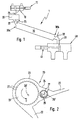
- FIG. 1 shows a schematic illustration of a device 1 to carry out the method according to the invention.
- the device 1 is used for all-round coating of short fibers Short fiber bundles.
- the device 1 has a pneumatic one Original changing device 11 provided storage container 10 for short fiber bundles.
- the reservoir 10 can with a Vibrating device should be provided, which the short fiber bundle in Movement keeps going.
- a device is connected to the storage container 10 20 for mechanical loosening of the short fiber bundles on.
- the device 20 can also be a vibrating device have and is via a feed shaft 21 for the fiber bundle entry connected to the reservoir 10 and opens out a rotary union 22 for the fiber bundle discharge in the actual Reactor 30 in the form of a rotatable reactor tube, in which the fiber bundle on all sides according to the inventive method be coated.
- the reactor 30 has at its upper end 30a, an opening 31 in the vicinity of the rotating union 22 for the reaction gas removal and at its lower end 30b one further opening 32 for the reaction gas supply.
- the reactor 30 can be replaced within the device 1, for. E.g. against a reactor with different dimensions.
- a material discharge 33 also opens at its lower end 30b, which the reactor 30 with a collecting device 40 for the fibers coated on all sides.
- the fall arrester 40 is also with a pneumatic document changing device 41 equipped.
- the document changing devices 11, 41 serve the necessary in the reactor 30 for CVD coating Ensure vacuum and the entry of extraneous gas into the reactor 30 to prevent.
- FIG. 2 shows a schematic representation of the device 20 for mechanical loosening of the fiber bundle.
- the device 20 is based on the fiber carding machines known from the textile industry. It consists essentially of a housing 23 with a funnel-shaped extension 24, into which the feed shaft 21 opens for the fiber bundle entry.
- a slow-running feed needle roller 25 Arranged in the housing 23 at the level of the mouth 24 is a slow-running feed needle roller 25 which, in the exemplary embodiment, rotates slowly about its longitudinal axis 25 'in the clockwise direction indicated by the arrow A.
- the rotational speed n 1 in the exemplary embodiment is approximately 5 to 10 rpm.
- a fast-running pick-up needle roller 26 is arranged immediately next to the feed needle roller 25.
- the pick-up needle roller rotates in the opposite direction to the feed needle roller 25, in the exemplary embodiment thus in the counterclockwise direction indicated by the arrow B, about its longitudinal axis 26 '.
- the rotational speed n 2 is significantly higher than the rotational speed n 1 and is approximately 5000 to 10000 rpm in the exemplary embodiment.
- Both rollers are equipped with fixed stainless steel needles 27. Their distance from one another, that is to say the distance between the two axes of rotation 25 ′ and 26 ′, is variable and can be set by the person skilled in the art as required.
- the configuration of the device 20, that is to say the width of the rollers 25 and 26, their spacing from one another, their rotational speed and the density of the placement with the stainless steel needles 27, can be adapted by the person skilled in the art to the amount and type of short fiber bundles to be treated.
- rollers with tooth-shaped, strip-shaped, knob-shaped and / or similar attachments are also conceivable.
- the rotating union 22 opens at the level of the customer needle roller 26 in the housing 23 of the device 20.
- the rotary union 22 is approximately at right angles to the feed shaft 21 arranged.
- FIG. 3 shows a schematic illustration of the reactor 30.
- the reactor 30 is actually a rotatable reactor tube and consists of a material which does not couple with microwaves, for example Al 2 O 3 , quartz or Teflon.
- a suitable material is e.g. Eg Alsint, an oxide ceramic made of sintered corundum (Al 2 O 3 ).
- Fiber drivers 32 are arranged on the inner surface 31 of the reactor 30.
- the fiber drivers 32 can be of various shapes, e.g. For example webs, bulges, indentations and others.
- the fiber drivers 32 can be arranged in a free-standing manner, projecting into the tube of the reactor 30 or rotating counter to the reactor 30. As shown in FIG.
- the reactor 30 is preferably arranged inclined by an angle of inclination a to the horizontal and has a length l.
- the reactor 30 rotates at a rotational speed n 3 in the direction of arrow C about its longitudinal axis 30 '.
- the residence time of the fiber bundles or fibers to be treated in the reactor can be controlled by the person skilled in the art via the length l, the angle of inclination a and the rotational speed n 3 .
- the reactor is heated by means of a high-frequency wave field, preferably a microwave field.
- a high-frequency wave field preferably a microwave field.
- This principle namely the combination of microwave heating with a homogeneous field based on the principle of a continuous microwave oven with a microwave-transparent process tube is described in German patent DE 37 06 336 C1.
- a comparable heating is also in WO 94/26077 described.
- a process support heater can also be provided be, e.g. For example via an induction heater and a susceptor and / or a microwave coupling radiation heater.
- a suitable continuous microwave oven is, for example, in the enclosed described earlier unpublished patent application.
- short fibers of approximately 3 to 30 mm in length were coated as follows.
- Commercially available short fiber bundles or recycled fiber bundles provided with size were fed from the storage container 10 through the feed shaft 21 to the device 20.
- the rollers 25, 26 By moving the rollers 25, 26 (rotational speeds: n 1 : 6 rpm; n 2 : 6000 rpm) and the action of the needles 27, the fiber bundles are transported and loosened mechanically.
- the loosened fiber bundles fall, favored by the centrifugal force and the reduced pressure and possibly supported by an inert gas flow, into the rotary union 22 and from there into the reactor 30.
- the reactor 30 had an angle of inclination a of 45 ° and a rotational speed n 3 of 5 to 10 rpm.
- a microwave field was built up inside the reactor 30. Through the opening 32, reaction gas was simultaneously fed into the reactor 30, which exited again through the opening 31.
- the adhesive size with the commercially available fiber bundles
- the adhesive matrix with the recycled fiber bundles
- the reactor 30 is heated by the microwave heating with a homogeneous field and / or by induction heating.
- the coated individual fibers came out of the reactor 30 the material discharge 33 into the collecting device 40.
- A can also be used to separate the fibers from the fiber bundles combined microwave, ultrasound and / or shock wave treatment be used.
- long residence times in the reactor 30 e.g. with long length 1 and / or small inclination angle a
- shock waves advantageous through which the fibers are kept in suspension in the reactor 30.
- reaction conditions can vary depending on the type of fibers and the desired coating.
- coatings made of titanium nitride (reaction gas: TiCl 4 / H 2 / N 2 ), pyrocarbon (reaction gas: H 2 / CH 4 ), silicon carbide (reaction gas: CH 3 SiCl 3 (MTS) / H 2 ) or graded C / SiC / Si layers (reaction gas: CH 3 SiCl 3 (MTS) / H 2 ).
- reaction conditions for different layer types are in the following table 1 as an example.
- FIGS. 6a to 6c show light microscopic images of commercially available, sized carbon fiber bundles in the raw state (FIG. 6a), after the mechanical loosening (FIG. 6b) and after the separation of the fibers in the microwave field (FIG. 6c).
- FIGS. 7a to 7c show corresponding images of recycled carbon fiber bundles. The loosening of the fiber bundles or the separation of the fibers can be clearly seen. The separation means that each individual fiber can be CVD coated on all sides.
- FIGS. 8a and 8b show fibers coated according to the invention, namely with a TiN layer (Figure 8a) or with an SiC layer ( Figure 8b).
- the layers are 15 to 30 nm thick. she are dense, continuous and replicate the fiber surface.
- layers are understood to mean: in their composition from pure carbon to silicon carbide transition to pure silicon or that of titanium carbide Change titanium carbonitride to titanium nitride.
- the variation of the reaction temperature favors a continuous transition between the individual compositions because of temperature changes be done relatively slowly in the range of minutes.
- the change of the reaction gas mixture takes place within a few seconds by changing the volume flows in the reaction gas supply within different reactor sections. This also works a continuous transition between the individual compositions associated.
- C- and / or Si-graded silicon carbide layers made of MTS / H 2 or C- and / or N-graded titanium carbonitride layers made of TiCl 4 / CH 4 / N 2 / H 2 can be deposited on carbon fibers ,
- Tables 2 and 3 show the chemical compositions of graded silicon carbide layers (Table 2) and graded titanium carbonitride layers (Table 3) depending on the deposition conditions.
- Temperature, ° C Reaction gas composition layer composition 1000 TiCl 4 / CH 4 / N 2 / H 2 TiC 0.3 N 0.7 1100 TiCl 4 / CH 4 / N 2 / H 2 TiC 0.7 N 0.3 1200 TiCl 4 / N 2 / H 2 TiN 1050 TiCl 4 / CH 4 / N 2 / H 2 TiCN 1100 TiCl 4 / CH 4 / N 2 / H 2 TiC 0.7 N 0.3 1100 TiCl 4 / CH 4 / H 2 TiC 0.7 N
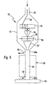
- FIG. 5 shows a further device 50 for the production of short fibers made of continuous fibers coated on all sides.
- the device 50 follows a known CVD coating system for continuous fibers, in which the fibers are initially continuous through a resistance oven for desizing and then passed through an IR oven for CVD coating.
- the IR oven is via a mouth 52 with the housing 51 of the device 50 connected.
- a roller 53 is arranged near the mouth 52, on which the coated indicated by the line 59 Continuous fibers are partially wound up.
- the continuous fibers 59 are then by a guide funnel 54 with one a knife 56 equipped cutting device 55, in which they are cut into short fibers.
- the short fibers fall through a guide funnel 57 into a post-coating reactor 60 with a vertically arranged reactor tube 61
- Post-coating reactor 60 has at its top that Cutting device 55 facing end 60a a reaction gas discharge 62 and a reaction gas supply at its lower end 60b 63 on.
- the dwell time of the short fibers is the length of the reactor tube 61 controlled.
- a collecting device 64 follows.
- short fibers were coated on all sides made from continuous fibers as follows. Endless carbon fibers (Tenax HTA 5331, 6000 filaments, Akzo) were in one Resistance furnace desized at 900 ° C in an inert gas stream and then in an IR oven with layers approximately 15 to 20 nm thick coated.
- the following table 4 shows the deposition conditions for various types of layers at a fiber pulling speed of approximately 90 to 130 m / h.
- the finished coated fibers were shown in FIG Device cut into variable lengths and in the post-coating system as already described for the short fibers in Post-coated microwave field. This made the free Interfaces sealed.
- the dwell time of the cut fibers in the post-coating reactor is shorter than that Short fiber bundle in the device shown in Figure 1.
- the at of the post-coating layer thicknesses to seal the Interfaces are therefore only about 5 to 6 nm. This is enough for the sealing effect.
- FIG. 9a shows such a ceramic composite material with uncoated Fibers (FIG. 9a) and fibers coated with SiC (FIG 9b).
- the increased fiber content caused by the coating is clearly visible.
- the increased fiber content leads to ductility of the composite material and the associated improved mechanical properties, in particular the avoidance of a brittle break.
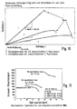
- FIG. 10 this is exemplified in the form of a Stress-strain diagram of ceramic composites shown.
- a coating prevents in metal matrix composite materials z.
- a reaction of the fiber surface with SiC or TiN of the molten metal e.g. Mg or Mg / Al alloys
- the coating serves as a diffusion and reaction barrier.
- This and the improved Wettability of the fibers by the matrix also leads to a Improvement of the mechanical properties of metal matrix composites.
- the three-point bending strengths are shown in FIG and the transverse tensile strengths of various metal matrix composites applied against each other at room temperature. These are matrices with unidirectional packages made of long carbon fibers with a fiber volume content of 50%.
- the composite material reinforced with TiN-coated fibers shows strengths that are similar to those of high-performance steel.
- the infiltration pressure can be up to to about 1/10 of the usual value (e.g. from 100 bar to below 10 bar) can be reduced.
Landscapes
- Chemical & Material Sciences (AREA)
- Engineering & Computer Science (AREA)
- Ceramic Engineering (AREA)
- Manufacturing & Machinery (AREA)
- Organic Chemistry (AREA)
- Materials Engineering (AREA)
- Structural Engineering (AREA)
- Inorganic Chemistry (AREA)
- Mechanical Engineering (AREA)
- Metallurgy (AREA)
- Chemical Kinetics & Catalysis (AREA)
- General Chemical & Material Sciences (AREA)
- Chemical Vapour Deposition (AREA)
- Chemical Or Physical Treatment Of Fibers (AREA)
Claims (17)
- Procédé de fabrication de fibres courtes revêtues, dans lequel on revêt les fibres courtes d'au moins un agent de revêtement dans un réacteur, caractérisé par le fait que l'on emploie des faisceaux de fibres courtes, recouverts de colle ou d'une matrice plastique, que l'on expose tout d'abord à un champ d'ondes de haute fréquence, ce par quoi la colle ou la matrice plastique se détache et les faisceaux de fibres se séparent en fibres individuelles et qu'ensuite on revêt directement de tous les côtés par dépôt en phase gazeuse par procédé chimique, dans un champ d'ondes de haute fréquence, les fibres, ainsi individualisées, d'au moins un agent de revêtement présent dans la phase gazeuse.
- Procédé de fabrication de fibres courtes revêtues à partir de fibres sans fin, dans lequel on désencolle tout d'abord thermiquement des faisceaux de fibres constitués de fibres sans fin, qu'ensuite on revêt les fibres individuelles résultantes et que l'on tronçonne les fibres sans fin, revêtues, pour obtenir des fibres courtes, caractérisé par le fait qu'après le tronçonnage, on revêt par dépôt en phase gazeuse par procédé chimique les bords de tronçonnage des fibres sans fin, aux extrémités non protégées apparaissant de ce fait, dans un champ d'ondes de haute fréquence, d'au moins un agent de revêtement présent dans la phase gazeuse.
- Procédé selon la revendication 1 ou 2, caractérisé par le fait que l'on emploie des fibres courtes de carbone, en particulier des fibres courtes de recyclage.
- Procédé selon l'une des revendications précédentes, caractérisé par le fait qu'avant leur introduction dans le champ d'ondes de haute fréquence, les faisceaux de fibres courtes sont soumis à, une ouvraison mécanique.
- Procédé selon l'une des revendications précédentes, caractérisé par le fait que comme champ d'ondes de haute fréquence on emploie un champ de micro-ondes.
- Procédé selon l'une des revendications précédentes, caractérisé par le fait que l'on revêt les fibres courtes de pyro-C et/ou de SiC et/ou Si.
- Procédé selon la revendication 6, caractérisé par le fait que l'on revêt les fibres courtes de carbone d'une couche de carbure de silicium graduée en C et/ou en Si.
- Procédé selon la revendication 7, caractérisé par le fait que dans une étape du revêtement la couche de carbure de silicium graduée se dépose par variation des paramètres de dépôt.
- Procédé selon l'une des revendications 6 à 8, caractérisé par le fait que comme agent de revêtement on emploie le méthyltrichlorosilane/hydrogène.
- Procédé selon l'une des revendications 1 à 5, caractérisé par le fait que l'on revêt les fibres courtes de pyro-C et/ou de IiN et/ou TuCN et/ou TiC.
- Procédé selon la revendication 10, caractérisé par le fait que l'on revêt les fibres courtes de carbone d'une couche de carbonitrure de titane graduée en C et/ou graduée en N.
- Procédé selon la revendication 11, caractérisé par le fait que, dans une étape du revêtement, la couche de carbonitrure de titane graduée se dépose par variation des paramètres de dépôt.
- Procédé selon l'une des revendications 10 à 12, caractérisé par le fait que comme agent de revêtement on emploie du tétrachlorure de titane avec de l'azote et éventuellement du méthane dans l'hydrogène.
- Procédé selon l'une des revendications précédentes, caractérisé par le fait que l'épaisseur du revêtement est commandée par la durée de séjour des fibres dans le réacteur.
- Fibres courtes de carbone revêtues, caractérisées par le fait qu'elles présentent une couche de carbure de silicium graduée en C et/ou graduée en Si.
- Fibres courtes de carbone revêtues, caractérisées par le fait qu'elles présentent une couche de carbonitrure de titane graduée en C et/ou en N.
- Emploi des fibres courtes selon l'une des revendications 15 ou 16 pour la fabrication de matériaux composites armés de fibres, en particulier de matériaux composites céramiques armés de fibres et de matériaux composites à matrice métallique armés de fibres.
Applications Claiming Priority (2)
| Application Number | Priority Date | Filing Date | Title |
|---|---|---|---|
| DE19828843A DE19828843B4 (de) | 1998-06-27 | 1998-06-27 | Verfahren zur Herstellung von beschichteten Kurzfasern |
| DE19828843 | 1998-06-27 |
Publications (3)
| Publication Number | Publication Date |
|---|---|
| EP0967190A1 EP0967190A1 (fr) | 1999-12-29 |
| EP0967190B1 true EP0967190B1 (fr) | 2002-08-28 |
| EP0967190B2 EP0967190B2 (fr) | 2010-01-20 |
Family
ID=7872307
Family Applications (1)
| Application Number | Title | Priority Date | Filing Date |
|---|---|---|---|
| EP99112209A Expired - Lifetime EP0967190B2 (fr) | 1998-06-27 | 1999-06-25 | Procédé de fabrication de fibres courtes revêtues |
Country Status (4)
| Country | Link |
|---|---|
| US (1) | US6143376A (fr) |
| EP (1) | EP0967190B2 (fr) |
| DE (2) | DE19828843B4 (fr) |
| ES (1) | ES2183461T5 (fr) |
Families Citing this family (19)
| Publication number | Priority date | Publication date | Assignee | Title |
|---|---|---|---|---|
| DE10007543B4 (de) * | 2000-02-18 | 2006-07-13 | Eads Space Transportation Gmbh | Verfahren zur Beschichtung von einer aus mehreren Filamenten bestehenden Faser |
| DE10026761C1 (de) | 2000-05-30 | 2002-01-10 | Daimler Chrysler Ag | Verfahren zur Wiederverwertung von Faserverbundwerkstoffen |
| US6630029B2 (en) * | 2000-12-04 | 2003-10-07 | General Electric Company | Fiber coating method and reactor |
| DE10101546B4 (de) * | 2001-01-15 | 2005-04-28 | Man Technologie Gmbh | Verfahren zur Herstellung einer hochtemperaturfesten Faserverbundkeramik und so hergestellte Bauteile |
| US20050186878A1 (en) * | 2004-02-23 | 2005-08-25 | General Electric Company | Thermo-mechanical property enhancement plies for CVI/SiC ceramic matrix composite laminates |
| KR100909363B1 (ko) * | 2006-07-21 | 2009-07-24 | 학교법인 포항공과대학교 | 전자기파 방사를 통한 탄소섬유의 표면 개질 방법 |
| US7851984B2 (en) * | 2006-08-08 | 2010-12-14 | Federal-Mogul World Wide, Inc. | Ignition device having a reflowed firing tip and method of construction |
| DE102008062350C5 (de) * | 2008-12-15 | 2016-03-31 | Carbo Tex Gmbh | Verfahren und Vorrichtung zum Rückgewinnen von Kohlenstofffasern und/oder Aktivkohlepartikeln |
| US10934219B2 (en) * | 2017-12-20 | 2021-03-02 | Raytheon Technologies Corporation | Method of increasing the uniformity of chemical vapor deposition on fibrous material through the imposition of pressure waves |
| FR3075829B1 (fr) * | 2017-12-26 | 2020-09-04 | Safran Ceram | Procede et dispositif de depot d'un revetement sur une fibre continue |
| FR3075830B1 (fr) * | 2017-12-26 | 2020-09-04 | Safran Ceram | Procede de depot d'un revetement sur des fibres courtes par calefaction |
| TWI663194B (zh) * | 2018-01-12 | 2019-06-21 | 永虹先進材料股份有限公司 | 碳纖維回收裝置 |
| TWI663192B (zh) * | 2018-01-12 | 2019-06-21 | 永虹先進材料股份有限公司 | Carbon fiber recycling method |
| FR3112149B1 (fr) * | 2020-07-01 | 2022-08-26 | Safran Ceram | Procédé de revêtement de fibres courtes |
| FR3113675B1 (fr) * | 2020-09-01 | 2022-09-09 | Safran Ceram | Procédé de revêtement de fibres en lit fluidisé |
| CN113278250A (zh) * | 2021-03-30 | 2021-08-20 | 上海凌云工业科技有限公司凌云汽车技术分公司 | 一种Ti3SiC2陶瓷增强复合材料的制备方法 |
| CN113956026B (zh) * | 2021-11-29 | 2022-08-30 | 福建师范大学泉港石化研究院 | 一种硼掺杂的硅酸铝陶瓷长纤维的制备方法 |
| DE102022101162B4 (de) * | 2022-01-19 | 2025-08-07 | Arianegroup Gmbh | Verfahren und Vorrichtung zum Beschichten von Kurzfasern |
| CN116514557B (zh) * | 2023-05-12 | 2024-08-02 | 北京航空航天大学 | 一种高效稳定制备SiC界面涂层的方法 |
Family Cites Families (12)
| Publication number | Priority date | Publication date | Assignee | Title |
|---|---|---|---|---|
| US4068037A (en) † | 1976-01-02 | 1978-01-10 | Avco Corporation | Silicon carbide filaments and method |
| US4315968A (en) † | 1980-02-06 | 1982-02-16 | Avco Corporation | Silicon coated silicon carbide filaments and method |
| EP0102489B1 (fr) * | 1982-07-31 | 1987-02-04 | BROWN, BOVERI & CIE Aktiengesellschaft | Supra-conducteur à filaments multiples et procédé de fabrication |
| DE3706218A1 (de) * | 1987-02-26 | 1988-09-08 | Werner Prof Dr Weisweiler | Vorrichtung und verfahren zur kontinuierlichen beschichtung der einzelnen fasern eines faserbuendels mit oberflaechenschuetzenden und haftvermittelnden carbid- oder plasmapolymer-filmen |
| US4960643A (en) * | 1987-03-31 | 1990-10-02 | Lemelson Jerome H | Composite synthetic materials |
| DE3933039A1 (de) * | 1989-10-04 | 1991-04-18 | Sintec Keramik Gmbh | Verfahren zur herstellung von oxidationsgeschuetzten cfc-formkoerpern |
| US5472650A (en) * | 1993-01-11 | 1995-12-05 | Northwestern University | Method of making chemical vapor infiltrated composites |
| NZ265292A (en) * | 1993-05-05 | 1997-07-27 | Ciba Geigy Ag | Oven and associated processing equipment for heating epoxy resin above its gelation temperature with decoupled electromagnetic heating units |
| JPH08231287A (ja) * | 1995-02-27 | 1996-09-10 | Yazaki Corp | 複合炭素繊維の製造方法 |
| DE19710105A1 (de) † | 1997-03-12 | 1998-09-17 | Sgl Technik Gmbh | Mit Graphitkurzfasern verstärkter Siliciumcarbidkörper |
| US5871844A (en) * | 1997-04-02 | 1999-02-16 | Fiberite, Inc. | Carbon--carbon parts having filamentized composite fiber substrates and methods of producing the same |
| DE19861035C2 (de) * | 1998-04-06 | 2000-11-30 | Daimler Chrysler Ag | Faserverbundwerkstoff und Verfahren zu dessen Herstellung |
-
1998
- 1998-06-27 DE DE19828843A patent/DE19828843B4/de not_active Expired - Lifetime
-
1999
- 1999-06-25 ES ES99112209T patent/ES2183461T5/es not_active Expired - Lifetime
- 1999-06-25 DE DE59902444T patent/DE59902444D1/de not_active Expired - Lifetime
- 1999-06-25 EP EP99112209A patent/EP0967190B2/fr not_active Expired - Lifetime
- 1999-06-28 US US09/340,199 patent/US6143376A/en not_active Expired - Lifetime
Also Published As
| Publication number | Publication date |
|---|---|
| ES2183461T3 (es) | 2003-03-16 |
| ES2183461T5 (es) | 2010-05-18 |
| EP0967190B2 (fr) | 2010-01-20 |
| DE59902444D1 (de) | 2002-10-02 |
| DE19828843B4 (de) | 2007-02-22 |
| US6143376A (en) | 2000-11-07 |
| DE19828843A1 (de) | 1999-12-30 |
| EP0967190A1 (fr) | 1999-12-29 |
Similar Documents
| Publication | Publication Date | Title |
|---|---|---|
| EP0967190B1 (fr) | Procédé de fabrication de fibres courtes revêtues | |
| DE3118123C2 (fr) | ||
| DE1925009C3 (de) | Faserverstärkter Verbundwerkstoff und seine Verwendung | |
| EP0011841B1 (fr) | Procédé et dispositif pour la fabrication d'objets façonnés en carbure de silicium | |
| EP1899494B1 (fr) | Procede de fabrication de couches ceramiques | |
| DE69025582T3 (de) | Beschichteter Hartmetallkörper und Verfahren zu seiner Herstellung | |
| DE2556679C2 (de) | Verbundwerkstoff und Verfahren zu seiner Herstellung | |
| EP1070027B1 (fr) | Fibres de renforcement et faisceau de fibres, notamment pour materiaux composites fibreux, procedes permettant de les produire et materiau composite fibreux muni de fibres de renforcement | |
| DE2141331A1 (de) | Pyrolytischen Graphit und Siliziumkarbid aufweisender Stoff sowie Verfahren und Vorrichtung zu seiner Herstellung | |
| DE69628425T2 (de) | Carbid-nanofibrillen und verfahren zum herstellen derselben | |
| DE69112198T2 (de) | Reaktor für die Beschichtung von optischen Fasern. | |
| DE69514013T2 (de) | Verstärkung für Verbundwerkstoff und diese verwendender Verbundwerkstoff | |
| DE1508895A1 (de) | Verfahren zur Herstellung von geformten Gegenstaenden unmittelbar aus Schmelzen niedriger Viskositaet | |
| DE69802759T2 (de) | Langfaserverstärkte, thermoplastische Formmasse | |
| DE69511469T2 (de) | Verfahren und Vorrichtung zur Herstellung von Diamanten | |
| DE69324767T2 (de) | Oxidationsbeständiger Kohlenstoff-Kohlenstoff Verbundstoff mit SiC-dotierter Matrix und dessen Herstellungsverfahren | |
| DE68922327T2 (de) | Verfahren zur Herstellung von Vliesstoffen aus Kohlenstoffasern. | |
| DE69418253T2 (de) | Verfahren zur Herstellung eines Verbundwerkstoffelements enthaltende eine auf flüssigem Wege erhaltene Faserverstärkung | |
| DE69830300T2 (de) | Hohle mikrofaser und herstellungsverfahren | |
| DE3426911C2 (fr) | ||
| DE2303407A1 (de) | Beschichteter kohlenstoffaden und verfahren zu seiner herstellung | |
| EP0111080B1 (fr) | Procédé de fabrication d'un matériau ceramique composite renforcé par des fibres | |
| DE69305229T2 (de) | Vorrichtung zur Herstellung einer hermetisch beschichteten optischen Faser | |
| DE4112749A1 (de) | Verfahren zum herstellen von faserverstaerkten verbundstoffen mittels abschleifen | |
| DE4331307C2 (de) | Herstellung eines mit Kohlenstoffasern verstärkten Verbundwerkstoffs und dessen Verwendung |
Legal Events
| Date | Code | Title | Description |
|---|---|---|---|
| PUAI | Public reference made under article 153(3) epc to a published international application that has entered the european phase |
Free format text: ORIGINAL CODE: 0009012 |
|
| AK | Designated contracting states |
Kind code of ref document: A1 Designated state(s): DE ES FR GB IT |
|
| AX | Request for extension of the european patent |
Free format text: AL;LT;LV;MK;RO;SI |
|
| 17P | Request for examination filed |
Effective date: 19991201 |
|
| AKX | Designation fees paid |
Free format text: DE ES FR GB IT |
|
| 17Q | First examination report despatched |
Effective date: 20010510 |
|
| GRAG | Despatch of communication of intention to grant |
Free format text: ORIGINAL CODE: EPIDOS AGRA |
|
| GRAG | Despatch of communication of intention to grant |
Free format text: ORIGINAL CODE: EPIDOS AGRA |
|
| GRAH | Despatch of communication of intention to grant a patent |
Free format text: ORIGINAL CODE: EPIDOS IGRA |
|
| GRAH | Despatch of communication of intention to grant a patent |
Free format text: ORIGINAL CODE: EPIDOS IGRA |
|
| GRAA | (expected) grant |
Free format text: ORIGINAL CODE: 0009210 |
|
| AK | Designated contracting states |
Kind code of ref document: B1 Designated state(s): DE ES FR GB IT |
|
| REG | Reference to a national code |
Ref country code: GB Ref legal event code: FG4D Free format text: NOT ENGLISH |
|
| RIC1 | Information provided on ipc code assigned before grant |
Free format text: 7C 04B 41/87 A, 7C 04B 35/628 B, 7C 04B 35/80 B, 7D 01F 11/12 B, 7C 22C 47/00 B, 7C 23C 16/54 B |
|
| REF | Corresponds to: |
Ref document number: 59902444 Country of ref document: DE Date of ref document: 20021002 |
|
| GBT | Gb: translation of ep patent filed (gb section 77(6)(a)/1977) |
Effective date: 20021022 |
|
| ET | Fr: translation filed | ||
| REG | Reference to a national code |
Ref country code: ES Ref legal event code: FG2A Ref document number: 2183461 Country of ref document: ES Kind code of ref document: T3 |
|
| PLBQ | Unpublished change to opponent data |
Free format text: ORIGINAL CODE: EPIDOS OPPO |
|
| PLBI | Opposition filed |
Free format text: ORIGINAL CODE: 0009260 |
|
| PLAX | Notice of opposition and request to file observation + time limit sent |
Free format text: ORIGINAL CODE: EPIDOSNOBS2 |
|
| 26 | Opposition filed |
Opponent name: SGL CARBON AG Effective date: 20030526 |
|
| PLAX | Notice of opposition and request to file observation + time limit sent |
Free format text: ORIGINAL CODE: EPIDOSNOBS2 |
|
| PLBB | Reply of patent proprietor to notice(s) of opposition received |
Free format text: ORIGINAL CODE: EPIDOSNOBS3 |
|
| RAP2 | Party data changed (patent owner data changed or rights of a patent transferred) |
Owner name: DAIMLERCHRYSLER AG |
|
| PLBQ | Unpublished change to opponent data |
Free format text: ORIGINAL CODE: EPIDOS OPPO |
|
| PLAB | Opposition data, opponent's data or that of the opponent's representative modified |
Free format text: ORIGINAL CODE: 0009299OPPO |
|
| R26 | Opposition filed (corrected) |
Opponent name: SGL CARBON AG Effective date: 20030526 |
|
| RDAF | Communication despatched that patent is revoked |
Free format text: ORIGINAL CODE: EPIDOSNREV1 |
|
| APBP | Date of receipt of notice of appeal recorded |
Free format text: ORIGINAL CODE: EPIDOSNNOA2O |
|
| APBQ | Date of receipt of statement of grounds of appeal recorded |
Free format text: ORIGINAL CODE: EPIDOSNNOA3O |
|
| APAA | Appeal reference recorded |
Free format text: ORIGINAL CODE: EPIDOS REFN |
|
| APAH | Appeal reference modified |
Free format text: ORIGINAL CODE: EPIDOSCREFNO |
|
| RAP2 | Party data changed (patent owner data changed or rights of a patent transferred) |
Owner name: DAIMLERCHRYSLER AG |
|
| RAP2 | Party data changed (patent owner data changed or rights of a patent transferred) |
Owner name: DAIMLER AG |
|
| PLAB | Opposition data, opponent's data or that of the opponent's representative modified |
Free format text: ORIGINAL CODE: 0009299OPPO |
|
| APBU | Appeal procedure closed |
Free format text: ORIGINAL CODE: EPIDOSNNOA9O |
|
| R26 | Opposition filed (corrected) |
Opponent name: SGL CARBON SE Effective date: 20030526 |
|
| PUAH | Patent maintained in amended form |
Free format text: ORIGINAL CODE: 0009272 |
|
| STAA | Information on the status of an ep patent application or granted ep patent |
Free format text: STATUS: PATENT MAINTAINED AS AMENDED |
|
| REG | Reference to a national code |
Ref country code: FR Ref legal event code: CD Ref country code: FR Ref legal event code: CA |
|
| 27A | Patent maintained in amended form |
Effective date: 20100120 |
|
| AK | Designated contracting states |
Kind code of ref document: B2 Designated state(s): DE ES FR GB IT |
|
| REG | Reference to a national code |
Ref country code: ES Ref legal event code: DC2A Date of ref document: 20100330 Kind code of ref document: T5 |
|
| REG | Reference to a national code |
Ref country code: GB Ref legal event code: 732E Free format text: REGISTERED BETWEEN 20110714 AND 20110720 |
|
| REG | Reference to a national code |
Ref country code: FR Ref legal event code: TP Owner name: FRENI BREMBO S.P.A., IT Effective date: 20110926 |
|
| REG | Reference to a national code |
Ref country code: ES Ref legal event code: PC2A Owner name: FRENI BREMBO S.P.A. Effective date: 20120210 |
|
| REG | Reference to a national code |
Ref country code: DE Ref legal event code: R081 Ref document number: 59902444 Country of ref document: DE Owner name: FRENI BREMBO S.P.A., CURNO, IT Free format text: FORMER OWNERS: DAIMLER AG, 70327 STUTTGART, DE; FREISTAAT BAYERN, VERTRETEN DURCH DIE FRIEDRICH-ALEXANDER-UNIVERSITAET ERLANGEN-NUERNBERG, 91052 ERLANGEN, DE Effective date: 20120125 Ref country code: DE Ref legal event code: R081 Ref document number: 59902444 Country of ref document: DE Owner name: FRENI BREMBO S.P.A., CURNO, IT Free format text: FORMER OWNER: DAIMLER AG, FREISTAAT BAYERN, VERTRETEN DUR, , DE Effective date: 20120125 |
|
| REG | Reference to a national code |
Ref country code: FR Ref legal event code: PLFP Year of fee payment: 18 |
|
| REG | Reference to a national code |
Ref country code: FR Ref legal event code: PLFP Year of fee payment: 19 |
|
| REG | Reference to a national code |
Ref country code: FR Ref legal event code: PLFP Year of fee payment: 20 |
|
| PGFP | Annual fee paid to national office [announced via postgrant information from national office to epo] |
Ref country code: IT Payment date: 20180611 Year of fee payment: 20 Ref country code: FR Payment date: 20180629 Year of fee payment: 20 |
|
| PGFP | Annual fee paid to national office [announced via postgrant information from national office to epo] |
Ref country code: GB Payment date: 20180620 Year of fee payment: 20 Ref country code: DE Payment date: 20180831 Year of fee payment: 20 Ref country code: ES Payment date: 20180702 Year of fee payment: 20 |
|
| REG | Reference to a national code |
Ref country code: DE Ref legal event code: R071 Ref document number: 59902444 Country of ref document: DE |
|
| REG | Reference to a national code |
Ref country code: GB Ref legal event code: PE20 Expiry date: 20190624 |
|
| PG25 | Lapsed in a contracting state [announced via postgrant information from national office to epo] |
Ref country code: GB Free format text: LAPSE BECAUSE OF EXPIRATION OF PROTECTION Effective date: 20190624 |
|
| REG | Reference to a national code |
Ref country code: ES Ref legal event code: FD2A Effective date: 20201204 |
|
| PG25 | Lapsed in a contracting state [announced via postgrant information from national office to epo] |
Ref country code: ES Free format text: LAPSE BECAUSE OF EXPIRATION OF PROTECTION Effective date: 20190626 |