EP0967344A2 - Elément plat de recouvrement d'une facade de bâtiment - Google Patents
Elément plat de recouvrement d'une facade de bâtiment Download PDFInfo
- Publication number
- EP0967344A2 EP0967344A2 EP99109585A EP99109585A EP0967344A2 EP 0967344 A2 EP0967344 A2 EP 0967344A2 EP 99109585 A EP99109585 A EP 99109585A EP 99109585 A EP99109585 A EP 99109585A EP 0967344 A2 EP0967344 A2 EP 0967344A2
- Authority
- EP
- European Patent Office
- Prior art keywords
- plate
- shaped
- overlap
- trough
- element according
- Prior art date
- Legal status (The legal status is an assumption and is not a legal conclusion. Google has not performed a legal analysis and makes no representation as to the accuracy of the status listed.)
- Withdrawn
Links
- XLYOFNOQVPJJNP-UHFFFAOYSA-N water Substances O XLYOFNOQVPJJNP-UHFFFAOYSA-N 0.000 claims abstract description 30
- 210000000078 claw Anatomy 0.000 claims description 12
- 238000005253 cladding Methods 0.000 claims description 6
- 238000006073 displacement reaction Methods 0.000 description 5
- 244000261422 Lysimachia clethroides Species 0.000 description 1
- 230000015572 biosynthetic process Effects 0.000 description 1
- 238000010276 construction Methods 0.000 description 1
- 238000009413 insulation Methods 0.000 description 1
- 238000009423 ventilation Methods 0.000 description 1
Images



Classifications
-
- E—FIXED CONSTRUCTIONS
- E04—BUILDING
- E04F—FINISHING WORK ON BUILDINGS, e.g. STAIRS, FLOORS
- E04F13/00—Coverings or linings, e.g. for walls or ceilings
- E04F13/07—Coverings or linings, e.g. for walls or ceilings composed of covering or lining elements; Sub-structures therefor; Fastening means therefor
- E04F13/08—Coverings or linings, e.g. for walls or ceilings composed of covering or lining elements; Sub-structures therefor; Fastening means therefor composed of a plurality of similar covering or lining elements
- E04F13/0801—Separate fastening elements
- E04F13/0803—Separate fastening elements with load-supporting elongated furring elements between wall and covering elements
- E04F13/081—Separate fastening elements with load-supporting elongated furring elements between wall and covering elements with additional fastening elements between furring elements and covering elements
- E04F13/0812—Separate fastening elements with load-supporting elongated furring elements between wall and covering elements with additional fastening elements between furring elements and covering elements fixed by means of spring action
-
- E—FIXED CONSTRUCTIONS
- E04—BUILDING
- E04F—FINISHING WORK ON BUILDINGS, e.g. STAIRS, FLOORS
- E04F13/00—Coverings or linings, e.g. for walls or ceilings
- E04F13/07—Coverings or linings, e.g. for walls or ceilings composed of covering or lining elements; Sub-structures therefor; Fastening means therefor
- E04F13/08—Coverings or linings, e.g. for walls or ceilings composed of covering or lining elements; Sub-structures therefor; Fastening means therefor composed of a plurality of similar covering or lining elements
- E04F13/0869—Coverings or linings, e.g. for walls or ceilings composed of covering or lining elements; Sub-structures therefor; Fastening means therefor composed of a plurality of similar covering or lining elements having conduits for fluids
-
- E—FIXED CONSTRUCTIONS
- E04—BUILDING
- E04F—FINISHING WORK ON BUILDINGS, e.g. STAIRS, FLOORS
- E04F13/00—Coverings or linings, e.g. for walls or ceilings
- E04F13/07—Coverings or linings, e.g. for walls or ceilings composed of covering or lining elements; Sub-structures therefor; Fastening means therefor
- E04F13/08—Coverings or linings, e.g. for walls or ceilings composed of covering or lining elements; Sub-structures therefor; Fastening means therefor composed of a plurality of similar covering or lining elements
- E04F13/0889—Coverings or linings, e.g. for walls or ceilings composed of covering or lining elements; Sub-structures therefor; Fastening means therefor composed of a plurality of similar covering or lining elements characterised by the joints between neighbouring elements, e.g. with joint fillings or with tongue and groove connections
Definitions
- the present invention relates to a plate-shaped element for the Cladding the facade of a building, the plate-shaped Element in the edge area with an adjacent, plate-shaped element can be attached overlapping to the building facade.
- a cover plate which on a House wall can be attached to clad the facade.
- battens to the wall of the house, which applied the insulation the house wall fixed and beyond that the attachment of the individual Cover plates serves.
- the arrangement of the individual cover plates on the House wall is now such that between cover plate and house wall or Battens there is a rear ventilation.
- a disadvantage of these known plates to cover the facade of a building is that this is during assembly be attached to the battens in an absolutely precise fit relative to each other have to.
- the invention is therefore based on the object of a plate-shaped Develop element of the type mentioned in such a way that a Displacement of the plate-shaped elements relative to each other, namely is possible in both the vertical and horizontal directions without there is a risk that, for example, in the event of driving rain Water can get behind the facade cladding.
- the plate-shaped Element on one edge of a water channel and on another, adjacent edge has an overlap groove and on this opposite edges each one over the length of the plate-shaped element extending roof-shaped projection having.
- both the water channel and the Overlap gutter opposite the top d. H. the surface of the plate-shaped element towards the rear, i.e. towards the facade are discontinued. Due to the arrangement described above both Water trough, as well as the overlap gutter is a Installed level surface provided that little attack for Pollution.
- the water channel is laterally in the direction of the plate-shaped element through a paragraph and towards the adjacent element formed by a bar. It follows that even when water gets into the water trough, it easily replenishes can run down and is prevented due to the side bar towards the adjacent plate-shaped element, behind the To arrive at facade cladding.
- the water surge bar follows in continuation of the Bottom of the overlap trough an overlap floor; in the area of roof-shaped protrusion on the underside is an angular tab provided the overlap bottom when assembling two encompasses plate-shaped elements.
- the distance from the upper edge preferably corresponds to Splash ledge to the top of the plate-shaped element of strength of the roof-shaped protrusion, i.e. the top of the protrusion forms a plane with the top of the plate-shaped element, so that one in the assembled state of several plate-shaped elements flat surface is created.
- the overlap floor itself has a border on the top, what as an additional safeguard against the ingress of water behind the Facade cladding serves.
- the underside shows the Overlap floor a ridge, which ensures that a plate-shaped element in spite of the angular tab on the Bottom of the roof-shaped projection is arranged, and the after gutter set back or down when assembling the panels a flat facade is created.
- a trough-shaped depression is arranged in the a claw nose arranged on the underside of the overlap groove assembled state engages two plate-shaped elements.
- the width of the claw nose is less than the width of the trough-shaped Deepening or the horizontal extension of the trough-shaped Deepening, exists in the installed state of the plate-shaped elements the possibility, within the width of the trough-shaped depression move neighboring plate horizontally; the measure of a possible The shift depends on how wide the trough-shaped Recess is designed, and how thick the claw nose is formed.
- the horizontal displacement of two plate-shaped elements relative to each other is at most such that the water channel is free lies, but through the plate still the ledge of the water channel is covered.
- the length of the claw ledge is such that it corresponds to the length of the trough-shaped recess corresponds to ensure that the Interlocking of claw nose into the trough-shaped recess Possibility of no play, so that two in the installed state plate-shaped elements arranged side by side, although horizontally, but are not displaceable in the vertical direction.
- the trough-shaped depression both deeper than the water channel, as well deeper than the overlap channel to prevent water from entering the to ensure trough-shaped depression, both from the Overlap channel, as well as from the water channel.
- Two plate-shaped elements are in the area of the overlap floor or the roof-shaped protrusion according to a special feature of Invention can be plugged into each other, fixable.
- Fixing clamp springs are provided, which can be attached to the facade, and on the one hand with the lower one, and on the other hand with the upper one plate-shaped element are connected.
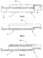
- plate-shaped element According to the representation of a visible in Figures 1 to 12 plate-shaped element or several plate-shaped elements in assembled state is the plate-shaped element itself with the Reference number 1 provided.
- the plate-shaped element has on it a transverse edge 10 a water trough 11 and the other opposite transverse edge 20 a roof-shaped projection 21.
- the water trough 11 is formed by one opposite the top 2 of the plate-shaped element formed paragraph 12, a channel bottom 13 and a strip 14 for delimiting the channel bottom 13.
- the overlap groove 31 which is formed by the paragraph 32 and the Water surge bar 33. Both the paragraph 32, and the water surge bar 33 delimit the bottom 34 of the overlap channel.
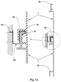
- the plate-shaped element 1 On the edge opposite the longitudinal edge 30 the plate-shaped element 1 is in turn a roof-shaped Overhang 40. In the area of the roof-shaped overhang 40 is one angular tab 50 arranged in the assembled state two plates engages behind the overlap base 35 (FIG. 2). On the Back of the plate-shaped element 1 is still the support bar 60 recognizable, which is parallel to the longitudinal edge 30 of the plate-shaped element 1 runs.
- An essential part of the invention is that designated 70 in total trough-shaped depression, as well as that at the opposite end of the Plate 1 arranged claw 80.
- the trough-shaped depression 70 is in the intersection 71 both the water channel 11, as also the overlap groove 31.
- the trough-shaped depression 70 is used for Recording of the water guided in the two channels 11 and 31, as well the drain down when the panels are installed.
- the length 72 the trough-shaped depression corresponds approximately to the length 82 of the Claw nose 80 which is in engagement with the trough-shaped recess.
- the trough-shaped depression itself is formed on the one hand by the in Wall extending in the longitudinal direction of the trough-shaped depression 72 73 and at the opposite end by a corresponding to the contour the wall-running bar 74, which is the continuation of the bar 14 of the Water trough 11 forms. Because the strength of the claw 80 essential is smaller than the width of the trough-shaped recess 72 thus the possibility of the claw 80 and thus the adjacent one Plate parallel to the longitudinal edge 30 of the plate-shaped element 1 move, until the claw with its contact edge 83 abuts the bar 74.
- the variation of the distance between two plates 1 in the vertical direction installed state results from the fact that the angular tab 50 on the underside of the plate-shaped element the overlap floor 35 engages, as has already been described.
- the width of the tab 50 is slightly larger than the width of the overlap groove 31, so that then when moving two plates 1 relative to each other in vertical direction, the overlap groove 31 is exposed, but on the A certain part of the overlap bottom through the flap 50 35 is gripped or engaged by the tab 50.
- On the top remains through the roof-shaped projection 40 of the upper plate-shaped Elements still covered the water surge strip 33. So it becomes clear that in the construction of the plate-shaped according to the invention Elementes the panels in the installed state in both horizontal and can also be shifted relative to each other in the vertical direction, without the risk of water behind the facade can reach.
- the water channel 11 itself does not extend over the entire width of the plate-shaped element, but forms a distance from the longitudinal edge of the plate, with the result that even when two plate-shaped ones are completely pushed together Elements in the vertical direction at least the trough-shaped depression 70 partly remains free.
- the water surge strip 33 has a height such that two in the assembled state plate-shaped elements 1 the tops 2 of two plate-shaped Elements 1 form a level. This means that the distance from the Top edge of the water surge strip 33 to the top 2 of the plate-shaped element of the thickness of a plate-shaped element 1 in Area of the roof-shaped projection 40 corresponds.
- a resilient element 100 is provided, which the border 36 engages around this, from which angled tab 50 is brought out like a gooseneck, then by means of fastening means 101, for example by screws, to be attached to the facade. It follows that the upper plate-shaped element 1 on the lower plate-shaped element stands up, at the same time this resilient element 100 in the area of angular tab 50 a clamp connection between the two produces plate-shaped elements 1.
Landscapes
- Engineering & Computer Science (AREA)
- Architecture (AREA)
- Civil Engineering (AREA)
- Structural Engineering (AREA)
- Roof Covering Using Slabs Or Stiff Sheets (AREA)
- Finishing Walls (AREA)
Applications Claiming Priority (2)
| Application Number | Priority Date | Filing Date | Title |
|---|---|---|---|
| DE29811247U DE29811247U1 (de) | 1998-06-24 | 1998-06-24 | Plattenförmiges Element für die Verkleidung der Fassade eines Gebäudes |
| DE29811247U | 1998-06-24 |
Publications (2)
| Publication Number | Publication Date |
|---|---|
| EP0967344A2 true EP0967344A2 (fr) | 1999-12-29 |
| EP0967344A3 EP0967344A3 (fr) | 2001-04-18 |
Family
ID=8058942
Family Applications (1)
| Application Number | Title | Priority Date | Filing Date |
|---|---|---|---|
| EP99109585A Withdrawn EP0967344A3 (fr) | 1998-06-24 | 1999-05-14 | Elément plat de recouvrement d'une facade de bâtiment |
Country Status (2)
| Country | Link |
|---|---|
| EP (1) | EP0967344A3 (fr) |
| DE (1) | DE29811247U1 (fr) |
Cited By (1)
| Publication number | Priority date | Publication date | Assignee | Title |
|---|---|---|---|---|
| WO2019020990A1 (fr) * | 2017-07-26 | 2019-01-31 | Ash & Lacy Holdings Limited | Système de façade |
Citations (1)
| Publication number | Priority date | Publication date | Assignee | Title |
|---|---|---|---|---|
| DE8718065U1 (de) | 1987-05-01 | 1993-05-27 | Vinylit Fassaden GmbH, 3500 Kassel | Profilierte Abdeckplatte oder -leiste |
Family Cites Families (4)
| Publication number | Priority date | Publication date | Assignee | Title |
|---|---|---|---|---|
| US2156277A (en) * | 1937-03-22 | 1939-05-02 | William C Biddle | House construction |
| BE783810A (fr) * | 1971-06-25 | 1972-09-18 | Oscar Joseph | Tuile et son procede de fabrication |
| US4343126A (en) * | 1979-02-26 | 1982-08-10 | Hoofe Iii William J | Interlocking panels |
| FR2502669B2 (fr) * | 1980-04-16 | 1986-04-25 | Beauchamp Michel | Element prefabrique pour la construction de panneaux de recouvrement, notamment pour toiture |
-
1998
- 1998-06-24 DE DE29811247U patent/DE29811247U1/de not_active Expired - Lifetime
-
1999
- 1999-05-14 EP EP99109585A patent/EP0967344A3/fr not_active Withdrawn
Patent Citations (1)
| Publication number | Priority date | Publication date | Assignee | Title |
|---|---|---|---|---|
| DE8718065U1 (de) | 1987-05-01 | 1993-05-27 | Vinylit Fassaden GmbH, 3500 Kassel | Profilierte Abdeckplatte oder -leiste |
Cited By (2)
| Publication number | Priority date | Publication date | Assignee | Title |
|---|---|---|---|---|
| WO2019020990A1 (fr) * | 2017-07-26 | 2019-01-31 | Ash & Lacy Holdings Limited | Système de façade |
| US11028596B2 (en) | 2017-07-26 | 2021-06-08 | Ash & Lacy Holdings Limited | Façade system |
Also Published As
| Publication number | Publication date |
|---|---|
| EP0967344A3 (fr) | 2001-04-18 |
| DE29811247U1 (de) | 1999-11-04 |
Similar Documents
| Publication | Publication Date | Title |
|---|---|---|
| DE2846275C2 (fr) | ||
| DE3328935T1 (de) | Laibungs- und gurtsimssystem | |
| DE10240939A1 (de) | Vorrichtung für die In-Dach-Verbindung von wenigstens zwei plattenförmigen Bauteilen auf einem Schrägdach | |
| EP2282141A2 (fr) | Agencement de montage de collecteur solaire dans un toit | |
| DE69920327T2 (de) | Bedachung aus gefaltetem Metallblech | |
| DE3512762A1 (de) | Flach ausgebildete dachabdeckungs- und fassadenelemente | |
| DE9409453U1 (de) | Vorrichtung zur Befestigung von rahmenlosen Solarmodulen | |
| DE202010002489U1 (de) | Indach-Solarkollektormontageanordnung | |
| EP1428948A1 (fr) | Caniveau d'écoulement | |
| DE3332841A1 (de) | Halter fuer eine ortgangblende und verkleidungssystem fuer einen ortgang mit organgblendenplatten | |
| DE19613043A1 (de) | Pfosten-Sprossen-Konstruktion | |
| DE29609135U1 (de) | Traufeneindeckungsplatte und Dachaufbau hiermit | |
| EP0150865B1 (fr) | Panneaux d'isolation thermiques déposés sur des chevrons | |
| DE29617121U1 (de) | Entwässerungsrinne für den Einbau vor Tür- oder Fensterelementen | |
| EP0967344A2 (fr) | Elément plat de recouvrement d'une facade de bâtiment | |
| CH719010B1 (de) | Leitvorrichtung zum Umlenken von Wasser in einer Wasserablaufrinne eines Schwimmbeckens sowie entsprechende Wasserablaufrinne. | |
| DE69613744T2 (de) | Schutzvorrichtung zum Verhindern des Eindringens von Wasser in eine Wand und zum Verbessern des Abführens von Wasser aus einer Wand | |
| DE3327868A1 (de) | Rasenabdeckung fuer strassenbankette | |
| DE8322275U1 (de) | Rasenabdeckplatte für Straßenbankette | |
| DD150918A5 (de) | Dacheindeckungsplatte mit waermeleitvorrichtung | |
| AT403495B (de) | Unterdachplatte | |
| EP0898029A2 (fr) | Couverture circulable pour un toit plat ou une terrasse | |
| DE19611808C2 (de) | Ortgangverkleidung | |
| DE3139009A1 (de) | Dacheindeckungsplatte mit einer oeffnung und einer die oeffnung durchgreifenden befestigungsvorrichtung | |
| DE2750223A1 (de) | Schwimmbecken-gitterrost |
Legal Events
| Date | Code | Title | Description |
|---|---|---|---|
| PUAI | Public reference made under article 153(3) epc to a published international application that has entered the european phase |
Free format text: ORIGINAL CODE: 0009012 |
|
| AK | Designated contracting states |
Kind code of ref document: A2 Designated state(s): AT BE CH CY DE DK ES FI FR GB GR IE IT LI LU MC NL PT SE |
|
| AX | Request for extension of the european patent |
Free format text: AL;LT;LV;MK;RO;SI |
|
| PUAL | Search report despatched |
Free format text: ORIGINAL CODE: 0009013 |
|
| AK | Designated contracting states |
Kind code of ref document: A3 Designated state(s): AT BE CH CY DE DK ES FI FR GB GR IE IT LI LU MC NL PT SE |
|
| AX | Request for extension of the european patent |
Free format text: AL;LT;LV;MK;RO;SI |
|
| AKX | Designation fees paid | ||
| REG | Reference to a national code |
Ref country code: DE Ref legal event code: 8566 |
|
| STAA | Information on the status of an ep patent application or granted ep patent |
Free format text: STATUS: THE APPLICATION IS DEEMED TO BE WITHDRAWN |
|
| 18D | Application deemed to be withdrawn |
Effective date: 20011203 |