EP0967433B1 - Projecteur de véhicule équipé d'un cache-lumière - Google Patents
Projecteur de véhicule équipé d'un cache-lumière Download PDFInfo
- Publication number
- EP0967433B1 EP0967433B1 EP19990112132 EP99112132A EP0967433B1 EP 0967433 B1 EP0967433 B1 EP 0967433B1 EP 19990112132 EP19990112132 EP 19990112132 EP 99112132 A EP99112132 A EP 99112132A EP 0967433 B1 EP0967433 B1 EP 0967433B1
- Authority
- EP
- European Patent Office
- Prior art keywords
- light shield
- light
- coating
- light source
- metal carbide
- Prior art date
- Legal status (The legal status is an assumption and is not a legal conclusion. Google has not performed a legal analysis and makes no representation as to the accuracy of the status listed.)
- Expired - Lifetime
Links
- 229910052751 metal Inorganic materials 0.000 claims description 17
- 239000002184 metal Substances 0.000 claims description 17
- 238000000576 coating method Methods 0.000 claims description 12
- 239000011248 coating agent Substances 0.000 claims description 11
- 239000002245 particle Substances 0.000 claims description 11
- 239000000919 ceramic Substances 0.000 claims description 6
- 238000005054 agglomeration Methods 0.000 claims description 5
- 230000002776 aggregation Effects 0.000 claims description 5
- MTPVUVINMAGMJL-UHFFFAOYSA-N trimethyl(1,1,2,2,2-pentafluoroethyl)silane Chemical group C[Si](C)(C)C(F)(F)C(F)(F)F MTPVUVINMAGMJL-UHFFFAOYSA-N 0.000 claims description 5
- 238000000034 method Methods 0.000 claims description 4
- 230000002745 absorbent Effects 0.000 claims description 3
- 239000002250 absorbent Substances 0.000 claims description 3
- 238000004519 manufacturing process Methods 0.000 claims description 3
- 238000004544 sputter deposition Methods 0.000 claims description 3
- 238000005546 reactive sputtering Methods 0.000 claims description 2
- 238000005524 ceramic coating Methods 0.000 claims 5
- 239000010408 film Substances 0.000 claims 2
- 239000002923 metal particle Substances 0.000 claims 2
- 238000009501 film coating Methods 0.000 claims 1
- 238000007788 roughening Methods 0.000 claims 1
- 239000010409 thin film Substances 0.000 claims 1
- 239000000463 material Substances 0.000 description 5
- VYZAMTAEIAYCRO-UHFFFAOYSA-N Chromium Chemical compound [Cr] VYZAMTAEIAYCRO-UHFFFAOYSA-N 0.000 description 4
- 230000008878 coupling Effects 0.000 description 3
- 238000010168 coupling process Methods 0.000 description 3
- 238000005859 coupling reaction Methods 0.000 description 3
- 230000001788 irregular Effects 0.000 description 3
- 230000003071 parasitic effect Effects 0.000 description 3
- PXHVJJICTQNCMI-UHFFFAOYSA-N Nickel Chemical compound [Ni] PXHVJJICTQNCMI-UHFFFAOYSA-N 0.000 description 2
- 229910000831 Steel Inorganic materials 0.000 description 2
- 239000011358 absorbing material Substances 0.000 description 2
- 230000004313 glare Effects 0.000 description 2
- 239000011521 glass Substances 0.000 description 2
- 238000010943 off-gassing Methods 0.000 description 2
- 239000000088 plastic resin Substances 0.000 description 2
- 239000004576 sand Substances 0.000 description 2
- 238000007789 sealing Methods 0.000 description 2
- 239000010959 steel Substances 0.000 description 2
- 238000012360 testing method Methods 0.000 description 2
- ATJFFYVFTNAWJD-UHFFFAOYSA-N Tin Chemical compound [Sn] ATJFFYVFTNAWJD-UHFFFAOYSA-N 0.000 description 1
- RTAQQCXQSZGOHL-UHFFFAOYSA-N Titanium Chemical compound [Ti] RTAQQCXQSZGOHL-UHFFFAOYSA-N 0.000 description 1
- HSFWRNGVRCDJHI-UHFFFAOYSA-N alpha-acetylene Natural products C#C HSFWRNGVRCDJHI-UHFFFAOYSA-N 0.000 description 1
- 238000005422 blasting Methods 0.000 description 1
- 238000005266 casting Methods 0.000 description 1
- 238000005336 cracking Methods 0.000 description 1
- 238000013461 design Methods 0.000 description 1
- 238000009713 electroplating Methods 0.000 description 1
- 238000005530 etching Methods 0.000 description 1
- 125000002534 ethynyl group Chemical group [H]C#C* 0.000 description 1
- 239000003292 glue Substances 0.000 description 1
- 229910052736 halogen Inorganic materials 0.000 description 1
- 230000008642 heat stress Effects 0.000 description 1
- 238000009434 installation Methods 0.000 description 1
- 238000002844 melting Methods 0.000 description 1
- 230000008018 melting Effects 0.000 description 1
- 238000005555 metalworking Methods 0.000 description 1
- 238000012986 modification Methods 0.000 description 1
- 230000004048 modification Effects 0.000 description 1
- 229910052759 nickel Inorganic materials 0.000 description 1
- 238000010422 painting Methods 0.000 description 1
- 238000012545 processing Methods 0.000 description 1
- 239000011347 resin Substances 0.000 description 1
- 229920005989 resin Polymers 0.000 description 1
- 150000003839 salts Chemical class 0.000 description 1
- 238000005488 sandblasting Methods 0.000 description 1
- 239000007787 solid Substances 0.000 description 1
- 239000007921 spray Substances 0.000 description 1
- 238000005477 sputtering target Methods 0.000 description 1
- 229910001220 stainless steel Inorganic materials 0.000 description 1
- 239000010935 stainless steel Substances 0.000 description 1
- 239000010936 titanium Substances 0.000 description 1
- 229910052719 titanium Inorganic materials 0.000 description 1
- 229910052721 tungsten Inorganic materials 0.000 description 1
- 239000010937 tungsten Substances 0.000 description 1
- -1 tungsten halogen Chemical class 0.000 description 1
Images

Classifications
-
- F—MECHANICAL ENGINEERING; LIGHTING; HEATING; WEAPONS; BLASTING
- F21—LIGHTING
- F21S—NON-PORTABLE LIGHTING DEVICES; SYSTEMS THEREOF; VEHICLE LIGHTING DEVICES SPECIALLY ADAPTED FOR VEHICLE EXTERIORS
- F21S41/00—Illuminating devices specially adapted for vehicle exteriors, e.g. headlamps
- F21S41/40—Illuminating devices specially adapted for vehicle exteriors, e.g. headlamps characterised by screens, non-reflecting members, light-shielding members or fixed shades
- F21S41/43—Illuminating devices specially adapted for vehicle exteriors, e.g. headlamps characterised by screens, non-reflecting members, light-shielding members or fixed shades characterised by the shape thereof
- F21S41/435—Hoods or cap-shaped
Definitions
- the invention relates to electric lamps and in particularly to vehicle lamps. More particularly the invention is concerned with a light shield as may be used in a headlamp, and a method of making a light shield. Such lights are known from document US 5 671 995 which could form a basis for the preamble of claim 1.
- Vehicle headlamps are commonly made with small, intense light sources. These light sources may be either tungsten halogen filament sources or high intensity discharge sources. Most of the generated light is controlled and directed by the reflector to be projected as a properly formed light beam. However, a portion of the light from the source goes directly forward and cannot be controlled by the reflector. Another portion of the light is reflected from nearby supports and wall structures that are closer to the source than is the reflector. These nearby objects then act as if they were secondary light sources acting as what is called parasitic sources. The directly projected light, and the reflections from parasitic sources are usually uncontrolled, and result in glare. It is frequently preferred to block this light with a light shield to limit the resulting glare.
- the light and heat reflected from the center of the reflector normally adds to the heat and light coming directly from the light source, to heat in a center spot of the exterior lamp lens.
- the center of the lens can then suffer heat stress. Again, it is frequently preferred to shield this light to protect the exterior lens.
- the light block or light shield may be a wall or similar structure placed intermediate the light source and the exterior.
- Light shields commonly have a cup shape.
- the light received in the light shield should not be reflected back out in an uncontrolled manner, so it is common to coat the inside surface of the light shield with a light absorbing material.
- the light shield frequently absorbs the received light and converts it to heat. As a result, the light shield becomes hot.
- the light absorbing material coating the light shield can either quickly or over time outgas material as the light shield bakes during lamp operation.
- the outgased material migrates in the enclosed headlamp, and condenses on the other structures, the reflector, the inside surface of the exterior lens, and even the light source itself.
- the resulting film may color the light or reduce the total amount of projected light.
- the headlamp looks dingy, and performs less well. There is then a need for an inexpensive light shield coating that does not outgas during the life of operation.
- a vehicle headlamp having a light shield may be formed from a vehicle housing defining an enclosed volume, and an opening; the housing enclosing a reflector, and a light source; a light shield being positioned intermediate the light source and the defined opening; the light shield according to claim 1 having a surface facing the light source including a layer of a high temperature ceramic; and a lens positioned to cover the defined opening.
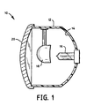
- FIG. 1 shows a preferred embodiment of a vehicle headlamp having a light shield.
- the vehicle headlamp 10 having a light shield is assembled from a housing 12, a reflector 14, a light source 16, light shield 18, and a lens 20.
- the vehicle housing 12 may be made out of bulk filled plastic resin to have the general form of a walled body defining an enclosed volume with an opening to the volume.
- a vehicle housing 12 usually includes a defined opening that is sufficient to allow the projection therethrough of a light beam with a pattern to illuminate the roadway sufficiently for the vehicle.
- the defined opening is usually a majority of the forward facing portion of the housing 12.
- the vehicle housing 12 may additionally include mounting and aiming hardware, electrical couplings, sealing and lens features as is generally known in the art. These additional features are a matter of design choice, and are not considered relevant here.
- the reflector 14 may be made out of smooth, high temperature resin to have the general form of a concave shell defining an interior volume with at least a portion of the interior surface being reflective.
- the vehicle housing 12 may alternatively be formed as a reflective internal housing wall.
- the light source 16 may be made out of tubular glass to have the general form of a tube section closed at each axial end.
- the vehicle housing 12 encloses the light source 16, and the reflector 14 is positioned to face the light source 16, so as to project a light beam through the defined opening in a forward direction.
- FIG. 2 shows a cross sectional view of a light shield 18.
- the light shield 18 may be made out of chrome plated steel to have the general form of a cup.
- the vehicle housing 12 encloses the light shield 18.
- the light shield 18 is positioned to be intermediate the light source 16 and the defined opening.
- the preferred light shield 18 has the form of a cup with a wall defining an exterior surface 22, and an interior surface 24. In the preferred embodiment the interior surface is roughened to assist in breaking up any possible light source image.
- the exterior surface 22 faces the defined opening.
- the preferred light shield 18 may be supported by an attachment leg 26, that is coupled to either the housing 12, or the reflector 14. In one embodiment the leg 26 was formed with a foot 28 that slid into a slot formed on the inner surface of the housing 12. The foot 28 may then be held in place by a screw, clip, friction, press fit, formed latch or other mechanical means.
- the ceramic inner layer 32 On the interior surface 24 of the light shield 18 is formed a ceramic inner layer 32.
- the ceramic inner layer 32 is not smooth. Rather, it is rough, pitted, or otherwise formed with crevices and peaks so as to form an irregular reflecting surface. Additionally the preferred ceramic inner layer 32 is highly absorbent with respect to visible light. The absorbent surface substantially reduces reflections from the inner layer 32. This prevents most of the impinging light from being reflected back to the light source 16 or the reflector 14. By forming the inner layer 32 in an irregular fashion, any image in the small amount of light that may be reflected is broken up by the surface irregularities.
- the light shield 18 then does not act as a false, or second light source (parasitic light source), and thereby does not project a false, glaring or otherwise undesirable secondary source images in the projected beam pattern.
- the preferred ceramic inner layer 32 is metal carbide, that is then resistant to heat, light absorbing, and not light reflecting. Titanium carbide has been found to have a very black or near black color with respect to visible light, and therefore is the preferred material.
- the preferred inner layer 32 may be formed by reactive sputtering process.
- the preferred method of making the coated light shield may be achieved by the following steps. First, a cup shaped light shield is formed as work piece from steel or other appropriate metal. This may be done by metal stamping, casting, or other convenient know metal working process. The cup is then cosmetically coated, at least on the exterior side, with a reflective metal coating, such as tin or nickel. This may be achieved by electroplating, or similar metal coating methods. Painting, and similar processes leaving outgasable coating components in the coating are discouraged.
- the interior surface of the light shield is then roughened. This may be achieved by particle blasting, or chemically etching the interior surface. The roughened interior surface helps bond subsequent coating, and helps break up any residual image reflection.
- the light shield is then placed a sputtering chamber with the cup interior facing the sputtering target.
- the chamber includes an organic gas component to react with the sputtered material.
- the preferred organic gas is acetylene.
- a metal is then sputtered in the chamber, so that the sputtered material impacts and adheres to the exposed interior surface of the light shield.
- the preferred metal is titanium, although others may be used. Titanium carbide is quite black, and highly resistant to heat.
- the sputtered metal passes through the organic gas, the two react to form a particle with a metal carbide surface, or solid particle of metal carbide. As these particles impact the interior surface of the light shield, the particles adhere to the surface, thereby building up an agglomeration of particles.
- This agglomeration in general follows the interior surface, which may be roughened, but the agglomeration from particle to particle is not smooth, but quite rough.
- the irregular agglomeration of titanium carbide particles then absorbs light falling on it, and to the extent any light is reflected, any image in the reflected light tends to be broken up.
- the sputtering is continued until a sufficient layer coats the interior surface of the cup.
- the foot of the light shield 18 may be fitted in a slot, screwed, snap fitted, or otherwise coupled by a chosen coupling to the housing 12. It is generally believed that an interference type mechanical coupling is the best.
- the currently available glues are suspected to be subject to outgassing, melting, cracking or otherwise failing.
- the lens 20 may be made out of glass or clear plastic to have the general form of a curved plate adapted with a sealing rim to mate with the housing 12.
- the vehicle housing 12 with the defined opening may then be sealed by the lens 20.
- the reflector 14, light source 16 and the light shield 18 are then enclosed by the lens 20.
- the vehicle housing was made of bulk filled plastic resin, and had a wall, a interior volume, a defined opening, a mounting and aiming hardware.
- the light shield may be made of cold rolled steal or stainless steel that is stamped into form.
- the Cup is then chrome plated.
- the interior is then sand blasted to roughen the surface. It is easier to chrome the whole cup, then to try to chrome only part of the cup, and chroming over a sand blasted area would reduce the effectiveness of the sand blasting.
- the cup exterior is then shielded and the cup interior is coated with titanium carbide.
- the cup has been tested for initial coating adhesion, heat resistance, photometrics, gloss and outgassing, and has passed the tests specified. Salt spray and color testing are in complete at this time.
- the disclosed dimensions, configurations and embodiments are as examples only, and other suitable configurations and relations may be used to implement the invention.
Landscapes
- Engineering & Computer Science (AREA)
- General Engineering & Computer Science (AREA)
- Non-Portable Lighting Devices Or Systems Thereof (AREA)
Claims (11)
- Ecran-paralume (18) pour une source de lumière très proche (16) pour une utilisation dans un phare d'automobile présentant un espace projeté de lumière, l'écran-paralume (18) comprenant :caractérisé en ce quea) une paroi présentant un premier côté (24) en regard de la source de lumière (16), de manière à définir une zone de l'espace du faisceau projeté devant être bloquée par l'écran-paralume (18) ; etb) un revêtement en film fin (32) d'une céramique collé au premier côté (24) en regard de la source de lumière (16),
le revêtement céramique est un revêtement de carbure métallique. - Écran-paralume selon la revendication 1, dans lequel le revêtement céramique (32) comprend un agglomérat de particules.
- Écran-paralume selon la revendication 1, dans lequel le revêtement céramique (32) présente une surface non-lisse.
- Écran-paralume selon la revendication 1, dans lequel la surface du revêtement céramique (32) est formée par pulvérisation réactive.
- Écran-paralume selon la revendication 1, dans lequel le premier côté (24) de la paroi présente une surface rugueuse avant d'acceuillir le revêtement céramique (32).
- Écran-paralume selon la revendication 1, dans lequel le carbure métallique est du carbure de titane.
- Écran-paralume selon la revendication 1, dans lequel le revêtement de carbure métallique est un revêtement à haute température.
- Écran-paralume selon la revendication 1, dans lequel le revêtement de carbure métallique est un revêtement absorbant la lumière.
- Phare (10) pour véhicule ayant un écran-paralume (18) comprenant :un boitier (12) de lampe de phare déterminant un volume fermé et une ouverture vers le volume;le boitier enfermant un réflecteur (14) et une source de lumière (16) ;l'écran-paralume (18) selon la revendication 1 étant positionné entre la source de lumière (16) et l'ouverture; etune lentille (20) disposée pour recouvrir l'ouverture.
- Procédé de réallisation d'un écran-paralume (18) pour une utilisation dans un phare pour automobile, comprenant les étapes suivantes :a) former une paroi d'écran-paralume avec un premier côté (24) en regard d'une source de lumière;b) rendre rugueux le premier côté (20) ; etc) coller un film (32) de carbure métallique sur le premier côté (24).
- Procédé selon la revendication 10, dans lequel le film (32) de carbure métallique est formé par pulvérisation de particules métalliques dans un gaz organique pour carburiser les particules métalliques projetées, et projeter les particules de carbure métallique obtenues sur le premier côté (24).
Applications Claiming Priority (2)
| Application Number | Priority Date | Filing Date | Title |
|---|---|---|---|
| US102793 | 1998-06-23 | ||
| US09/102,793 US6012830A (en) | 1998-06-23 | 1998-06-23 | Light shield for a vehicle headlamp |
Publications (3)
| Publication Number | Publication Date |
|---|---|
| EP0967433A2 EP0967433A2 (fr) | 1999-12-29 |
| EP0967433A3 EP0967433A3 (fr) | 2001-05-02 |
| EP0967433B1 true EP0967433B1 (fr) | 2003-09-17 |
Family
ID=22291696
Family Applications (1)
| Application Number | Title | Priority Date | Filing Date |
|---|---|---|---|
| EP19990112132 Expired - Lifetime EP0967433B1 (fr) | 1998-06-23 | 1999-06-23 | Projecteur de véhicule équipé d'un cache-lumière |
Country Status (4)
| Country | Link |
|---|---|
| US (1) | US6012830A (fr) |
| EP (1) | EP0967433B1 (fr) |
| CA (1) | CA2268601C (fr) |
| DE (1) | DE69911315T2 (fr) |
Cited By (2)
| Publication number | Priority date | Publication date | Assignee | Title |
|---|---|---|---|---|
| DE10330906B4 (de) * | 2002-07-16 | 2006-08-24 | Visteon Global Technologies, Inc., Dearborn | Eine Fahrzeugleuchte und ein Fahrzeugbeleuchtungs- und Datenübertragungssystem, in dem diese Fahrzeugleuchte enthalten ist |
| DE102007057539A1 (de) * | 2007-11-29 | 2009-06-04 | Volkswagen Ag | Scheinwerfer für ein Fahrzeug, insbesondere für ein Kraftfahrzeug |
Families Citing this family (19)
| Publication number | Priority date | Publication date | Assignee | Title |
|---|---|---|---|---|
| JP2000021227A (ja) * | 1998-04-27 | 2000-01-21 | Stanley Electric Co Ltd | 車両用前照灯 |
| DE19824053A1 (de) * | 1998-05-29 | 1999-12-02 | Hella Kg Hueck & Co | Beleuchtungseinrichtung für Fahrzeuge |
| US6375341B1 (en) * | 1999-08-20 | 2002-04-23 | Elco Textron, Inc. | Electro-formed bulb shield and method of making same |
| JP2001118409A (ja) * | 1999-10-19 | 2001-04-27 | Koito Mfg Co Ltd | 車両用前照灯 |
| US6890090B2 (en) * | 2001-08-08 | 2005-05-10 | Automotive Lighting Reutlingen Gmbh | Headlight for a motor vehicle |
| WO2003031871A2 (fr) * | 2001-10-05 | 2003-04-17 | Elco Textron Inc. | Ecran de lampe |
| US6641293B2 (en) | 2001-10-31 | 2003-11-04 | Visteon Global Technologies, Inc. | Light shield with reflective inner surface |
| US6786624B2 (en) * | 2002-05-06 | 2004-09-07 | North American Lighting, Inc. | High temperature lighting bulb shield |
| FR2848285B1 (fr) * | 2002-12-05 | 2005-12-16 | Valeo Vision | Procede de realisation d'une fonction optique sur un composant d'un dispositif d'eclairage ou de signalisation automobile |
| DE10338785A1 (de) * | 2003-08-23 | 2005-03-17 | Hella Kgaa Hueck & Co. | Beleuchtungseinrichtung für Fahrzeuge |
| US7017040B2 (en) | 2003-12-04 | 2006-03-21 | Intel Corporation | BIOS update file |
| US7014346B2 (en) * | 2004-03-08 | 2006-03-21 | Valeo Sylvania L.L.C. | Light shield mounting for automotive headlamp |
| US20060034093A1 (en) * | 2004-08-16 | 2006-02-16 | Michael Strazzanti | Heat resistant bulb sheild |
| US7604386B2 (en) * | 2005-11-18 | 2009-10-20 | Federal-Mogul World Wide, Inc | Lamp assembly having a socket made from high temperature plastic |
| US7748881B2 (en) * | 2007-01-08 | 2010-07-06 | Isatec Of Ohio, Inc. | Tailor welded strip bulb shield |
| KR20080106760A (ko) * | 2007-06-04 | 2008-12-09 | 삼성전자주식회사 | 광원유닛 및 이를 갖는 영상투사장치 |
| FR2942022B1 (fr) * | 2009-02-10 | 2011-02-11 | Peugeot Citroen Automobiles Sa | Bloc optique pour vehicule comprenant notamment une bonnette a cellules photovoltaiques recuperant l'energie lumineuse de la source lumineuse de ce bloc |
| ITTO20120667A1 (it) * | 2012-07-27 | 2014-01-28 | Automotive Lighting Italia Spa | Dispositivo oscuratore per una sorgente luminosa e dispositivo di illuminazione per veicoli equipaggiato con lo stesso |
| US10240737B2 (en) * | 2017-03-06 | 2019-03-26 | Ford Global Technologies, Llc | Vehicle light assembly |
Family Cites Families (17)
| Publication number | Priority date | Publication date | Assignee | Title |
|---|---|---|---|---|
| CH631743A5 (de) * | 1977-06-01 | 1982-08-31 | Balzers Hochvakuum | Verfahren zum aufdampfen von material in einer vakuumaufdampfanlage. |
| US5144539A (en) * | 1987-07-09 | 1992-09-01 | Dai-Ichi Seiko Co., Ltd. | Illumination device |
| GB2222179B (en) * | 1987-10-01 | 1992-04-08 | Gen Electric | Protective coatings for metallic articles |
| US4992153A (en) * | 1989-04-26 | 1991-02-12 | Balzers Aktiengesellschaft | Sputter-CVD process for at least partially coating a workpiece |
| US4990229A (en) * | 1989-06-13 | 1991-02-05 | Plasma & Materials Technologies, Inc. | High density plasma deposition and etching apparatus |
| DE3920835C2 (de) * | 1989-06-24 | 1997-12-18 | Leybold Ag | Einrichtung zum Beschichten von Substraten |
| US5234560A (en) * | 1989-08-14 | 1993-08-10 | Hauzer Holdings Bv | Method and device for sputtering of films |
| US5010458A (en) * | 1989-09-01 | 1991-04-23 | General Motors Corporation | Headlamp assembly |
| DE4038497C1 (fr) * | 1990-12-03 | 1992-02-20 | Leybold Ag, 6450 Hanau, De | |
| US5126033A (en) * | 1990-12-31 | 1992-06-30 | Leybold Aktiengesellschaft | Process and apparatus for reactively coating a substrate |
| DE69310493T2 (de) * | 1992-08-14 | 1997-12-18 | Hughes Aircraft Co | Oberflächepräparation und beschichtungs-methode für titannitrid auf gusseisen |
| US5346600A (en) * | 1992-08-14 | 1994-09-13 | Hughes Aircraft Company | Plasma-enhanced magnetron-sputtered deposition of materials |
| FR2699164B1 (fr) * | 1992-12-11 | 1995-02-24 | Saint Gobain Vitrage Int | Procédé de traitement de couches minces à base d'oxyde ou de nitrure métallique. |
| DE59309954D1 (de) * | 1992-12-21 | 2000-03-16 | Balzers Hochvakuum | Optisches Bauelement, Verfahren zur Herstellung einer Schicht, Schicht bzw. Schichtsystem und Verwendung des Bauelementes |
| JP3394610B2 (ja) * | 1994-11-18 | 2003-04-07 | 株式会社小糸製作所 | 自動車用ヘッドランプ |
| DE19530950B4 (de) * | 1995-08-23 | 2006-11-16 | Automotive Lighting Reutlingen Gmbh | Scheinwerfer für Fahrzeuge |
| US5601654A (en) * | 1996-05-31 | 1997-02-11 | The Regents Of The University Of California, Office Of Technology Transfer | Flow-through ion beam source |
-
1998
- 1998-06-23 US US09/102,793 patent/US6012830A/en not_active Expired - Lifetime
-
1999
- 1999-04-06 CA CA 2268601 patent/CA2268601C/fr not_active Expired - Fee Related
- 1999-06-23 EP EP19990112132 patent/EP0967433B1/fr not_active Expired - Lifetime
- 1999-06-23 DE DE1999611315 patent/DE69911315T2/de not_active Expired - Lifetime
Cited By (3)
| Publication number | Priority date | Publication date | Assignee | Title |
|---|---|---|---|---|
| DE10330906B4 (de) * | 2002-07-16 | 2006-08-24 | Visteon Global Technologies, Inc., Dearborn | Eine Fahrzeugleuchte und ein Fahrzeugbeleuchtungs- und Datenübertragungssystem, in dem diese Fahrzeugleuchte enthalten ist |
| DE102007057539A1 (de) * | 2007-11-29 | 2009-06-04 | Volkswagen Ag | Scheinwerfer für ein Fahrzeug, insbesondere für ein Kraftfahrzeug |
| DE102007057539B4 (de) * | 2007-11-29 | 2017-08-31 | Volkswagen Ag | Scheinwerfer für ein Fahrzeug, insbesondere für ein Kraftfahrzeug |
Also Published As
| Publication number | Publication date |
|---|---|
| CA2268601C (fr) | 2008-06-10 |
| DE69911315D1 (de) | 2003-10-23 |
| EP0967433A3 (fr) | 2001-05-02 |
| DE69911315T2 (de) | 2004-04-01 |
| EP0967433A2 (fr) | 1999-12-29 |
| US6012830A (en) | 2000-01-11 |
| CA2268601A1 (fr) | 1999-12-23 |
Similar Documents
| Publication | Publication Date | Title |
|---|---|---|
| EP0967433B1 (fr) | Projecteur de véhicule équipé d'un cache-lumière | |
| US6280071B1 (en) | Vehicular headlamp with integrated aiming bracket | |
| US5199779A (en) | Projection-type vehicular headlamp | |
| JP2788533B2 (ja) | 自動車用ヘッドランプ | |
| JPH0479101A (ja) | 車輌用前照灯 | |
| CA2047846C (fr) | Phare pour vehicule motorise | |
| US4747029A (en) | Headlamp assembly | |
| JPH097404A (ja) | 車両用灯具 | |
| JP2008506227A (ja) | 赤外線ランプの製造方法 | |
| JP2004039329A (ja) | 自動車用前照灯 | |
| US20060062009A1 (en) | Vehicle lamp | |
| GB2360775A (en) | A line-type film forming method for a discharge headlamp reflector | |
| JP2763716B2 (ja) | 車両用灯具 | |
| JP2001023427A (ja) | 放電灯装置及び車両用前照灯 | |
| JP3207380B2 (ja) | 車両用前照灯 | |
| JP2003115206A (ja) | 車両用灯具 | |
| JP4040306B2 (ja) | 灯具及びリフレクタ製造方法 | |
| CN219530644U (zh) | 高亮度车灯反射结构 | |
| JPH0883502A (ja) | 防曇処理を施した車両用灯具 | |
| JP2963306B2 (ja) | 反射鏡付管球およびその製造方法 | |
| JPH08321205A (ja) | 投射型自動車用ヘッドランプ | |
| JP3197208B2 (ja) | 車輌用前照灯 | |
| JP2000149642A (ja) | 放電バルブを光源とする車両用灯具 | |
| KR0119171Y1 (ko) | 조명램프의 반사경 | |
| JP3054664B2 (ja) | 多層膜反射鏡 |
Legal Events
| Date | Code | Title | Description |
|---|---|---|---|
| PUAI | Public reference made under article 153(3) epc to a published international application that has entered the european phase |
Free format text: ORIGINAL CODE: 0009012 |
|
| AK | Designated contracting states |
Kind code of ref document: A2 Designated state(s): BE DE FR GB IT NL |
|
| AX | Request for extension of the european patent |
Free format text: AL;LT;LV;MK;RO;SI |
|
| RAP1 | Party data changed (applicant data changed or rights of an application transferred) |
Owner name: VALEO SYLVANIA L.L.C. |
|
| PUAL | Search report despatched |
Free format text: ORIGINAL CODE: 0009013 |
|
| AK | Designated contracting states |
Kind code of ref document: A3 Designated state(s): AT BE CH CY DE DK ES FI FR GB GR IE IT LI LU MC NL PT SE |
|
| AX | Request for extension of the european patent |
Free format text: AL;LT;LV;MK;RO;SI |
|
| 17P | Request for examination filed |
Effective date: 20010615 |
|
| AKX | Designation fees paid |
Free format text: BE DE FR GB IT NL |
|
| 17Q | First examination report despatched |
Effective date: 20020416 |
|
| GRAH | Despatch of communication of intention to grant a patent |
Free format text: ORIGINAL CODE: EPIDOS IGRA |
|
| GRAH | Despatch of communication of intention to grant a patent |
Free format text: ORIGINAL CODE: EPIDOS IGRA |
|
| GRAA | (expected) grant |
Free format text: ORIGINAL CODE: 0009210 |
|
| AK | Designated contracting states |
Kind code of ref document: B1 Designated state(s): BE DE FR GB IT NL |
|
| REG | Reference to a national code |
Ref country code: GB Ref legal event code: FG4D |
|
| RIC1 | Information provided on ipc code assigned before grant |
Ipc: 7F 21S 8/10 A |
|
| REF | Corresponds to: |
Ref document number: 69911315 Country of ref document: DE Date of ref document: 20031023 Kind code of ref document: P |
|
| ET | Fr: translation filed | ||
| PLBE | No opposition filed within time limit |
Free format text: ORIGINAL CODE: 0009261 |
|
| STAA | Information on the status of an ep patent application or granted ep patent |
Free format text: STATUS: NO OPPOSITION FILED WITHIN TIME LIMIT |
|
| 26N | No opposition filed |
Effective date: 20040618 |
|
| REG | Reference to a national code |
Ref country code: FR Ref legal event code: PLFP Year of fee payment: 18 |
|
| PGFP | Annual fee paid to national office [announced via postgrant information from national office to epo] |
Ref country code: NL Payment date: 20170515 Year of fee payment: 19 |
|
| REG | Reference to a national code |
Ref country code: FR Ref legal event code: PLFP Year of fee payment: 19 |
|
| PGFP | Annual fee paid to national office [announced via postgrant information from national office to epo] |
Ref country code: FR Payment date: 20170630 Year of fee payment: 19 Ref country code: GB Payment date: 20170616 Year of fee payment: 19 Ref country code: DE Payment date: 20170614 Year of fee payment: 19 |
|
| PGFP | Annual fee paid to national office [announced via postgrant information from national office to epo] |
Ref country code: BE Payment date: 20170627 Year of fee payment: 19 Ref country code: IT Payment date: 20170619 Year of fee payment: 19 |
|
| REG | Reference to a national code |
Ref country code: DE Ref legal event code: R082 Ref document number: 69911315 Country of ref document: DE |
|
| REG | Reference to a national code |
Ref country code: DE Ref legal event code: R079 Ref document number: 69911315 Country of ref document: DE Free format text: PREVIOUS MAIN CLASS: F21S0008100000 Ipc: F21S0043000000 |
|
| REG | Reference to a national code |
Ref country code: DE Ref legal event code: R119 Ref document number: 69911315 Country of ref document: DE |
|
| REG | Reference to a national code |
Ref country code: NL Ref legal event code: MM Effective date: 20180701 |
|
| GBPC | Gb: european patent ceased through non-payment of renewal fee |
Effective date: 20180623 |
|
| REG | Reference to a national code |
Ref country code: BE Ref legal event code: MM Effective date: 20180630 |
|
| PG25 | Lapsed in a contracting state [announced via postgrant information from national office to epo] |
Ref country code: NL Free format text: LAPSE BECAUSE OF NON-PAYMENT OF DUE FEES Effective date: 20180701 |
|
| PG25 | Lapsed in a contracting state [announced via postgrant information from national office to epo] |
Ref country code: FR Free format text: LAPSE BECAUSE OF NON-PAYMENT OF DUE FEES Effective date: 20180630 Ref country code: IT Free format text: LAPSE BECAUSE OF NON-PAYMENT OF DUE FEES Effective date: 20180623 Ref country code: GB Free format text: LAPSE BECAUSE OF NON-PAYMENT OF DUE FEES Effective date: 20180623 Ref country code: DE Free format text: LAPSE BECAUSE OF NON-PAYMENT OF DUE FEES Effective date: 20190101 |
|
| PG25 | Lapsed in a contracting state [announced via postgrant information from national office to epo] |
Ref country code: BE Free format text: LAPSE BECAUSE OF NON-PAYMENT OF DUE FEES Effective date: 20180630 |