EP0967443A2 - Luftkühlungsanordnung eines Raumes - Google Patents
Luftkühlungsanordnung eines Raumes Download PDFInfo
- Publication number
- EP0967443A2 EP0967443A2 EP99850110A EP99850110A EP0967443A2 EP 0967443 A2 EP0967443 A2 EP 0967443A2 EP 99850110 A EP99850110 A EP 99850110A EP 99850110 A EP99850110 A EP 99850110A EP 0967443 A2 EP0967443 A2 EP 0967443A2
- Authority
- EP
- European Patent Office
- Prior art keywords
- air
- primary air
- mixing chamber
- space
- room air
- Prior art date
- Legal status (The legal status is an assumption and is not a legal conclusion. Google has not performed a legal analysis and makes no representation as to the accuracy of the status listed.)
- Granted
Links
- 238000001816 cooling Methods 0.000 title claims abstract description 38
- 238000005192 partition Methods 0.000 claims abstract description 27
- 230000006698 induction Effects 0.000 claims abstract description 10
- 239000002184 metal Substances 0.000 claims abstract description 4
- 239000000203 mixture Substances 0.000 claims abstract description 4
- 230000000694 effects Effects 0.000 abstract description 9
- 238000004378 air conditioning Methods 0.000 description 2
- 238000010438 heat treatment Methods 0.000 description 2
- 239000000463 material Substances 0.000 description 2
- 238000004140 cleaning Methods 0.000 description 1
- 238000010276 construction Methods 0.000 description 1
- 239000004744 fabric Substances 0.000 description 1
- 239000012528 membrane Substances 0.000 description 1
- 230000000644 propagated effect Effects 0.000 description 1
- 238000012216 screening Methods 0.000 description 1
- 230000003068 static effect Effects 0.000 description 1
- 230000032258 transport Effects 0.000 description 1
- 238000009423 ventilation Methods 0.000 description 1
- XLYOFNOQVPJJNP-UHFFFAOYSA-N water Substances O XLYOFNOQVPJJNP-UHFFFAOYSA-N 0.000 description 1
Images
Classifications
-
- F—MECHANICAL ENGINEERING; LIGHTING; HEATING; WEAPONS; BLASTING
- F24—HEATING; RANGES; VENTILATING
- F24F—AIR-CONDITIONING; AIR-HUMIDIFICATION; VENTILATION; USE OF AIR CURRENTS FOR SCREENING
- F24F1/00—Room units for air-conditioning, e.g. separate or self-contained units or units receiving primary air from a central station
- F24F1/01—Room units for air-conditioning, e.g. separate or self-contained units or units receiving primary air from a central station in which secondary air is induced by injector action of the primary air
-
- F—MECHANICAL ENGINEERING; LIGHTING; HEATING; WEAPONS; BLASTING
- F24—HEATING; RANGES; VENTILATING
- F24F—AIR-CONDITIONING; AIR-HUMIDIFICATION; VENTILATION; USE OF AIR CURRENTS FOR SCREENING
- F24F2221/00—Details or features not otherwise provided for
- F24F2221/14—Details or features not otherwise provided for mounted on the ceiling
Definitions
- the invention relates to a ceiling-mounted device for cooling room air which includes a longitudinal primary air duct, a room air cooling battery, a mixing chamber for cooled room air and primary air, and means for delivering primary air to the mixing chamber through the medium of an induction effect by means of which room air is sucked into the device and is passed through the cooling battery to the mixing chamber.
- the device also includes one or more outlet ducts through which a mixture of cold room air and the primary air leave the device.
- Cooling baffles Devices of the aforesaid kind are also referred to as cooling baffles or false ceiling panels. Such devices are known for treating room air and are available in different designs, including designs in which natural ventilation generated by a chimney effect is used instead of primary air, although a common feature of those cooling baffles that use primary air of the aforesaid kind is that they include one or more primary air channels to which primary air can be delivered through a central air-conditioning plant installed either in the building concerned or in the proximity of said building, or which is sucked-in from outside by fans provided to this end, so that the pressure in the primary air channel will always be higher than atmospheric pressure. The primary air is blown into the baffle interior through such devices as nozzles for instance, and the influence of said pressure.
- cooling baffles are lean in energy and do not generate draughts. The level of noise generated is also relatively low.
- An object of the present invention is to provide a room air cooling device of the cooling baffle type that uses induction with the aid of a primary air supply, so as to obtain a lower noise level or, alternatively, a higher capacity without raising the sound level.
- the invention is characterised to this end by the features set forth in the accompanying Claims.
- the primary air channel of the inventive device is divided into two spaces separated by a longitudinally extending air-permeable partition wall, wherein the first space, which receives primary air from an outer source, is delimited with respective flow from the second space which forms that part of the primary air channel in which said primary air supply means is arranged adjacent the partition wall or walls delimiting the mixing chamber.
- the kinetic energy of the primary air in the first space is propagated only partially and generally only vertically to the second space, although the static air pressure in the primary air channel will, of course, be able to adjust equally in the whole of the primary air channel despite the presence of the partition wall, which can be designed in several different ways to provide such an effect and which may consist of different types of permeable membranes made of fabric, plastic or like materials, although metal is perhaps the simplest material from the aspect of construction and also the most hygienic.
- the air permeable partition wall may thus conveniently have the form of a perforated plate with a perforated area of about 50%.
- the partition wall or walls between the second space and the mixing chamber may suitably be disposed generally transversely to the flow direction in the adjacent outlet channel.
- the inventive device may have many different configurations within the scope of the Claims and cooling baffles and like induction apparatus of the aforementioned kind forming part of the known art may, in many cases, include a divided primary air channel.
- a particularly preferred embodiment of the device is one in which the part of the device that lies outside the first primary air channel space has a triangular cross-sectional shape, wherein the second primary air channel space forms the upper part of the triangle, the mixing chamber forms the centre-most part of the triangle, and the cooling coil and its surrounding air outlet channels connected to the mixing chamber forms the lower part of the triangle.
- the triangle is preferably an isosceles triangle having an upper obtuse angle, such that the height of this part will be smaller than its width.
- the second primary air channel space is suitably delimited by five walls, of which one is horizontal and forms a lower air-impermeable delimiting wall of the mixing chamber, of which two are said partition walls facing towards the mixing chamber, and of which two are said partition walls facing towards the first primary air channel space.
- the lower delimiting wall will conveniently be removable, so as to facilitate cleaning of the second primary air channel space.
- inventive cooling baffles When comparing inventive cooling baffles with earlier known versions of cooling baffles, it was noted that the sound level generated with the inventive baffles was up to 20% lower than the dBA values generated with the known baffles. However, this can only be seen as an indication to the effect that the inventive baffle generates lower sound levels, since known cooling baffles can generate different sound levels and since the sound levels generated by some older designs may be substantially greater.
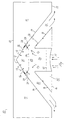
- the cooling baffle 10 includes a primary air channel having a first space 11 to which primary air 12 is delivered from an external source (not shown).
- the baffle 10 also includes an outer casing 13, which delimits the primary air channel outwards, and inner walls 14 which delimit the primary air channel against the remainder of the baffle, which comprises a lower part 15 having a lower plate 16 which forms an outer, lower delimiting wall 17 of the lower part 15 and two outlet channel walls 18, and which together with an upper plate 19 also forms an upper delimiting wall of the lower part 15, said plates preferably being removable.
- the lower part 15 accommodates one or more cooling coils 20 mounted in a coil holder 21 and functioning to cool room air that flows in through openings (not shown) in the lower wall 17.
- the mixing chamber 23 is disposed above the lower part 15 and is delimited downwards by the upper plate 19 of the lower part 15, on one side of parts of the inner walls 14 that delimit the space 11, and delimited upwards by a lower air-impermeable delimiting wall 24 of the second space 25 of the primary air channel.
- the second primary air channel space 25 has a pentahedral/?/ cross-sectional shape and is separated from the first primary air channel space 11 by an air-permeable partition wall 26, normally comprised of perforated sheet metal and, in the illustrated case, bent to form an obtuse angle at its upper ridge-like part 27.
- the space 25 is also delimited by two obliquely extending partition walls 28 which border on the mixing chamber 23 and define generally a right angle with the partition walls 26 and the inner walls 14 extending parallel with said partition walls.
- Provided in each partition wall 28 in the longitudinal direction of the device 10 are mutually spaced nozzles 29 through which primary air is blown from the primary air channel into the mixing chamber 23.
- the cooling baffle shall be used as a 1-way baffle, the nozzles 29 shown in the higher rows may be blocked or removed and the holes plugged.
- a screening plate 30, shown in a broken line, may also be fitted in this case.
- the overpressure in the primary air channels 11, 25 will cause primary air 12 to be blown in through the nozzles 29, so as to form a subpressure in the mixing chamber 23.
- This subpressure contributes towards sucking room air into the baffle (through induction) as illustrated by the upwardly pointing arrows, and up through the cooling coil 20 and into the mixing chamber 23.
- the primary air blown into the device transports the room air sucked in by induction down through the outlet channels 22 and out along the ceiling of the room, as indicated by arrows.
- the primary air delivered to and flowing through the first space 11 of the primary air channel flows through the holes in the air-permeable partition wall 26 and moves into the second primary air channel space 25 essentially from above and downwards.
Landscapes
- Engineering & Computer Science (AREA)
- Chemical & Material Sciences (AREA)
- Combustion & Propulsion (AREA)
- Mechanical Engineering (AREA)
- General Engineering & Computer Science (AREA)
- Duct Arrangements (AREA)
- Sorption Type Refrigeration Machines (AREA)
Applications Claiming Priority (2)
| Application Number | Priority Date | Filing Date | Title |
|---|---|---|---|
| SE9802215 | 1998-06-23 | ||
| SE9802215A SE521038C2 (sv) | 1998-06-23 | 1998-06-23 | Takmonterad anordning för kylning av rumsluft samt tillförsel av tilluft |
Publications (3)
| Publication Number | Publication Date |
|---|---|
| EP0967443A2 true EP0967443A2 (de) | 1999-12-29 |
| EP0967443A3 EP0967443A3 (de) | 2000-09-27 |
| EP0967443B1 EP0967443B1 (de) | 2003-10-15 |
Family
ID=20411793
Family Applications (1)
| Application Number | Title | Priority Date | Filing Date |
|---|---|---|---|
| EP19990850110 Expired - Lifetime EP0967443B1 (de) | 1998-06-23 | 1999-06-22 | Luftkühlungsanordnung eines Raumes |
Country Status (4)
| Country | Link |
|---|---|
| EP (1) | EP0967443B1 (de) |
| DE (1) | DE69912030T2 (de) |
| NO (1) | NO318402B1 (de) |
| SE (1) | SE521038C2 (de) |
Cited By (11)
| Publication number | Priority date | Publication date | Assignee | Title |
|---|---|---|---|---|
| WO2000028263A1 (en) * | 1998-11-05 | 2000-05-18 | Teknoterm Climate Ab | Airconditioning device |
| FR2807501A1 (fr) * | 2000-04-06 | 2001-10-12 | Halton Oy | Systeme d'amenee d'air dans une piece d'un batiment |
| EP1188992A3 (de) * | 2000-09-13 | 2002-04-24 | ABB Fläkt AB | Luftbehandlung und Belüftungsvorrichtung |
| GB2371357A (en) * | 2000-11-24 | 2002-07-24 | Halton Oy | An air conditioner terminal device with air mixing control for a room |
| GB2371853A (en) * | 2000-12-07 | 2002-08-07 | Halton Oy | An air conditioner unit for a room with angled nozzles. |
| EP1319902A1 (de) | 2001-12-07 | 2003-06-18 | Fläkt Woods AB | Heizeinrichtung zur Deckenmontage |
| US6715538B2 (en) | 2000-11-24 | 2004-04-06 | Halton Oy | Supply air terminal device |
| EP1637815A1 (de) * | 2004-06-10 | 2006-03-22 | Lindab AB | Belüftungsvorrichtung |
| GB2491039A (en) * | 2011-05-20 | 2012-11-21 | Frenger Systems Ltd | Induction type air conditioner having a primary air chamber body and a separate discharge member coupled thereto |
| IT201800003335A1 (it) * | 2018-03-07 | 2019-09-07 | Aermec Spa | Unita' di condizionamento dell'aria per interni |
| NO20181398A1 (no) * | 2018-10-31 | 2020-05-01 | Trox Auranor Norge As | Kjølebaffel |
Families Citing this family (1)
| Publication number | Priority date | Publication date | Assignee | Title |
|---|---|---|---|---|
| SE532506C2 (sv) | 2008-03-31 | 2010-02-09 | Lindab Ab | Förfarande och anordning för ventilering av ett utrymme |
Citations (5)
| Publication number | Priority date | Publication date | Assignee | Title |
|---|---|---|---|---|
| GB1011742A (en) | 1961-10-03 | 1965-12-01 | Carrier Corp | Improvements in or relating to an induction type room air conditioning unit |
| GB1274540A (en) | 1969-11-14 | 1972-05-17 | Hendrik Jacobus Spoormaker | Improvements in air conditioning and in air conditioning terminal units therefor |
| GB1468754A (en) | 1973-06-02 | 1977-03-30 | Ltg Lufttechnische Gmbh | Air conditioning apparatus |
| DE3321612A1 (de) | 1983-06-15 | 1984-12-20 | Howaldtswerke-Deutsche Werft Ag Hamburg Und Kiel, 2300 Kiel | Klimageraet |
| GB2271175A (en) | 1992-09-25 | 1994-04-06 | Halton Oy | Space air heating or cooling device |
Family Cites Families (4)
| Publication number | Priority date | Publication date | Assignee | Title |
|---|---|---|---|---|
| US3824909A (en) * | 1970-04-08 | 1974-07-23 | Cgt Corp | Distribution system for clean rooms |
| SE460923B (sv) * | 1987-04-16 | 1989-12-04 | Farex As | Straalnings- och konvektionselement foer undertaksmontage |
| US5725427A (en) * | 1996-01-24 | 1998-03-10 | Chemfab Corporation | Fabric air diffuser, method for diffusing air, and method for attenuating noise associated with flowing air |
| SE516349C2 (sv) * | 1996-08-26 | 2001-12-17 | Stifab Farex Ab | Anordning för kylning av rumsluft |
-
1998
- 1998-06-23 SE SE9802215A patent/SE521038C2/sv not_active IP Right Cessation
-
1999
- 1999-06-22 NO NO19993087A patent/NO318402B1/no unknown
- 1999-06-22 EP EP19990850110 patent/EP0967443B1/de not_active Expired - Lifetime
- 1999-06-22 DE DE1999612030 patent/DE69912030T2/de not_active Expired - Fee Related
Patent Citations (5)
| Publication number | Priority date | Publication date | Assignee | Title |
|---|---|---|---|---|
| GB1011742A (en) | 1961-10-03 | 1965-12-01 | Carrier Corp | Improvements in or relating to an induction type room air conditioning unit |
| GB1274540A (en) | 1969-11-14 | 1972-05-17 | Hendrik Jacobus Spoormaker | Improvements in air conditioning and in air conditioning terminal units therefor |
| GB1468754A (en) | 1973-06-02 | 1977-03-30 | Ltg Lufttechnische Gmbh | Air conditioning apparatus |
| DE3321612A1 (de) | 1983-06-15 | 1984-12-20 | Howaldtswerke-Deutsche Werft Ag Hamburg Und Kiel, 2300 Kiel | Klimageraet |
| GB2271175A (en) | 1992-09-25 | 1994-04-06 | Halton Oy | Space air heating or cooling device |
Cited By (20)
| Publication number | Priority date | Publication date | Assignee | Title |
|---|---|---|---|---|
| US6520247B2 (en) | 1998-11-05 | 2003-02-18 | Teknoterm Climate Ab | Airconditioning device |
| WO2000028263A1 (en) * | 1998-11-05 | 2000-05-18 | Teknoterm Climate Ab | Airconditioning device |
| FR2807501A1 (fr) * | 2000-04-06 | 2001-10-12 | Halton Oy | Systeme d'amenee d'air dans une piece d'un batiment |
| BE1014102A3 (fr) * | 2000-04-06 | 2003-04-01 | Halton Oy | Systeme d'amenee d'air. |
| EP1188992A3 (de) * | 2000-09-13 | 2002-04-24 | ABB Fläkt AB | Luftbehandlung und Belüftungsvorrichtung |
| GB2371357B (en) * | 2000-11-24 | 2004-11-24 | Halton Oy | Supply air terminal device |
| GB2371357A (en) * | 2000-11-24 | 2002-07-24 | Halton Oy | An air conditioner terminal device with air mixing control for a room |
| US7000688B2 (en) | 2000-11-24 | 2006-02-21 | Halton Oy | Supply air terminal device |
| US6715538B2 (en) | 2000-11-24 | 2004-04-06 | Halton Oy | Supply air terminal device |
| US6769477B2 (en) | 2000-12-07 | 2004-08-03 | Halton Oy | Supply air terminal device |
| GB2371853A (en) * | 2000-12-07 | 2002-08-07 | Halton Oy | An air conditioner unit for a room with angled nozzles. |
| GB2371853B (en) * | 2000-12-07 | 2005-04-27 | Halton Oy | Supply air terminal device |
| EP1319902A1 (de) | 2001-12-07 | 2003-06-18 | Fläkt Woods AB | Heizeinrichtung zur Deckenmontage |
| EP1637815A1 (de) * | 2004-06-10 | 2006-03-22 | Lindab AB | Belüftungsvorrichtung |
| GB2491039A (en) * | 2011-05-20 | 2012-11-21 | Frenger Systems Ltd | Induction type air conditioner having a primary air chamber body and a separate discharge member coupled thereto |
| GB2491039B (en) * | 2011-05-20 | 2017-02-01 | Frenger Systems Ltd | Improvements in or relating to air conditioning modules |
| IT201800003335A1 (it) * | 2018-03-07 | 2019-09-07 | Aermec Spa | Unita' di condizionamento dell'aria per interni |
| EP3537056A1 (de) * | 2018-03-07 | 2019-09-11 | AERMEC S.p.A. | Klimaanlageneinheit für innenräume |
| NO20181398A1 (no) * | 2018-10-31 | 2020-05-01 | Trox Auranor Norge As | Kjølebaffel |
| NO345103B1 (no) * | 2018-10-31 | 2020-09-28 | Trox Auranor Norge As | Kjølebaffel |
Also Published As
| Publication number | Publication date |
|---|---|
| EP0967443B1 (de) | 2003-10-15 |
| SE9802215L (sv) | 1999-12-24 |
| DE69912030D1 (de) | 2003-11-20 |
| NO993087L (no) | 1999-12-27 |
| NO993087D0 (no) | 1999-06-22 |
| DE69912030T2 (de) | 2004-07-22 |
| SE9802215D0 (sv) | 1998-06-23 |
| SE521038C2 (sv) | 2003-09-23 |
| EP0967443A3 (de) | 2000-09-27 |
| NO318402B1 (no) | 2005-03-14 |
Similar Documents
| Publication | Publication Date | Title |
|---|---|---|
| US6213867B1 (en) | Venturi type air distribution system | |
| EP0967443B1 (de) | Luftkühlungsanordnung eines Raumes | |
| EP0199762B2 (de) | Vorrichtung und verfahren zum belüften von zimmern | |
| JP5626588B2 (ja) | 空調システム | |
| US20090264062A1 (en) | Ventilation system | |
| CA2520330C (en) | A system for directing and controlling two separate streams of air to a kitchen | |
| IE920336A1 (en) | Filter/ventilator apparatus for use in clean rooms | |
| JP2019105383A (ja) | 空調ユニット | |
| EP0967444B1 (de) | Vorrichtung zum Belüften, Kühlen und/oder Beheizen eines Raumes | |
| JP6767616B2 (ja) | 送風装置 | |
| JP2020169813A (ja) | 空調ユニット | |
| KR102537504B1 (ko) | 감염병 전파 방지를 위한 공조 설비 | |
| JP3936962B1 (ja) | 輻射空調ユニット | |
| JP6493997B2 (ja) | 空調装置 | |
| EP1122501A1 (de) | An der Decke montierte Vorrichtung zur Raumbelüftung und gleichzeitige Luft-Kühlung oder Heizung von Räumen | |
| KR20230147933A (ko) | 소음 저감구조를 갖는 상치형 환기장치 | |
| JP4574317B2 (ja) | 暖房空調方法及び暖房空調システム | |
| JP4597769B2 (ja) | クリーンルーム及びその設計施工方法 | |
| JP4357975B2 (ja) | クリーンルーム用空調装置および空調方法 | |
| KR102899349B1 (ko) | 에어폴 인덕션 쿡킹존을 갖는 인덕션 쿡탑 시스템 | |
| EP3387329B1 (de) | Zuluftvorrichtung | |
| KR102348740B1 (ko) | 전열교환기가 구비된 수직기류형 냉방시스템 | |
| JP3229774U (ja) | 換気システム | |
| JP2522705B2 (ja) | 空調用送風装置 | |
| JP2006046671A (ja) | ファン内蔵二重床パネル及びこれを備えた室内空調システム |
Legal Events
| Date | Code | Title | Description |
|---|---|---|---|
| PUAI | Public reference made under article 153(3) epc to a published international application that has entered the european phase |
Free format text: ORIGINAL CODE: 0009012 |
|
| AK | Designated contracting states |
Kind code of ref document: A2 Designated state(s): DE FI FR GB IT NL SE |
|
| AX | Request for extension of the european patent |
Free format text: AL;LT;LV;MK;RO;SI |
|
| PUAL | Search report despatched |
Free format text: ORIGINAL CODE: 0009013 |
|
| AK | Designated contracting states |
Kind code of ref document: A3 Designated state(s): AT BE CH CY DE DK ES FI FR GB GR IE IT LI LU MC NL PT SE |
|
| AX | Request for extension of the european patent |
Free format text: AL;LT;LV;MK;RO;SI |
|
| RIC1 | Information provided on ipc code assigned before grant |
Free format text: 7F 24F 1/01 A, 7F 24F 13/24 B |
|
| 17P | Request for examination filed |
Effective date: 20010319 |
|
| AKX | Designation fees paid |
Free format text: DE FI FR GB IT NL SE |
|
| GRAH | Despatch of communication of intention to grant a patent |
Free format text: ORIGINAL CODE: EPIDOS IGRA |
|
| GRAS | Grant fee paid |
Free format text: ORIGINAL CODE: EPIDOSNIGR3 |
|
| GRAA | (expected) grant |
Free format text: ORIGINAL CODE: 0009210 |
|
| AK | Designated contracting states |
Kind code of ref document: B1 Designated state(s): DE FI FR GB IT NL SE |
|
| REG | Reference to a national code |
Ref country code: GB Ref legal event code: FG4D |
|
| REF | Corresponds to: |
Ref document number: 69912030 Country of ref document: DE Date of ref document: 20031120 Kind code of ref document: P |
|
| PG25 | Lapsed in a contracting state [announced via postgrant information from national office to epo] |
Ref country code: SE Free format text: LAPSE BECAUSE OF FAILURE TO SUBMIT A TRANSLATION OF THE DESCRIPTION OR TO PAY THE FEE WITHIN THE PRESCRIBED TIME-LIMIT Effective date: 20040115 |
|
| ET | Fr: translation filed | ||
| PLBE | No opposition filed within time limit |
Free format text: ORIGINAL CODE: 0009261 |
|
| STAA | Information on the status of an ep patent application or granted ep patent |
Free format text: STATUS: NO OPPOSITION FILED WITHIN TIME LIMIT |
|
| 26N | No opposition filed |
Effective date: 20040716 |
|
| PGFP | Annual fee paid to national office [announced via postgrant information from national office to epo] |
Ref country code: FR Payment date: 20050530 Year of fee payment: 7 |
|
| PGFP | Annual fee paid to national office [announced via postgrant information from national office to epo] |
Ref country code: GB Payment date: 20050608 Year of fee payment: 7 |
|
| PGFP | Annual fee paid to national office [announced via postgrant information from national office to epo] |
Ref country code: FI Payment date: 20050615 Year of fee payment: 7 |
|
| PGFP | Annual fee paid to national office [announced via postgrant information from national office to epo] |
Ref country code: NL Payment date: 20050620 Year of fee payment: 7 |
|
| PGFP | Annual fee paid to national office [announced via postgrant information from national office to epo] |
Ref country code: DE Payment date: 20050624 Year of fee payment: 7 |
|
| PG25 | Lapsed in a contracting state [announced via postgrant information from national office to epo] |
Ref country code: GB Free format text: LAPSE BECAUSE OF NON-PAYMENT OF DUE FEES Effective date: 20060622 Ref country code: FI Free format text: LAPSE BECAUSE OF NON-PAYMENT OF DUE FEES Effective date: 20060622 |
|
| PG25 | Lapsed in a contracting state [announced via postgrant information from national office to epo] |
Ref country code: NL Free format text: LAPSE BECAUSE OF NON-PAYMENT OF DUE FEES Effective date: 20070101 |
|
| PG25 | Lapsed in a contracting state [announced via postgrant information from national office to epo] |
Ref country code: DE Free format text: LAPSE BECAUSE OF NON-PAYMENT OF DUE FEES Effective date: 20070103 |
|
| GBPC | Gb: european patent ceased through non-payment of renewal fee |
Effective date: 20060622 |
|
| NLV4 | Nl: lapsed or anulled due to non-payment of the annual fee |
Effective date: 20070101 |
|
| REG | Reference to a national code |
Ref country code: FR Ref legal event code: ST Effective date: 20070228 |
|
| PG25 | Lapsed in a contracting state [announced via postgrant information from national office to epo] |
Ref country code: FR Free format text: LAPSE BECAUSE OF NON-PAYMENT OF DUE FEES Effective date: 20060630 |
|
| PGFP | Annual fee paid to national office [announced via postgrant information from national office to epo] |
Ref country code: IT Payment date: 20110620 Year of fee payment: 13 |
|
| PG25 | Lapsed in a contracting state [announced via postgrant information from national office to epo] |
Ref country code: IT Free format text: LAPSE BECAUSE OF NON-PAYMENT OF DUE FEES Effective date: 20120622 |