EP1319902A1 - Heizeinrichtung zur Deckenmontage - Google Patents
Heizeinrichtung zur Deckenmontage Download PDFInfo
- Publication number
- EP1319902A1 EP1319902A1 EP02445162A EP02445162A EP1319902A1 EP 1319902 A1 EP1319902 A1 EP 1319902A1 EP 02445162 A EP02445162 A EP 02445162A EP 02445162 A EP02445162 A EP 02445162A EP 1319902 A1 EP1319902 A1 EP 1319902A1
- Authority
- EP
- European Patent Office
- Prior art keywords
- air
- room
- metal panel
- supply
- outflow
- Prior art date
- Legal status (The legal status is an assumption and is not a legal conclusion. Google has not performed a legal analysis and makes no representation as to the accuracy of the status listed.)
- Withdrawn
Links
Images


Classifications
-
- F—MECHANICAL ENGINEERING; LIGHTING; HEATING; WEAPONS; BLASTING
- F24—HEATING; RANGES; VENTILATING
- F24F—AIR-CONDITIONING; AIR-HUMIDIFICATION; VENTILATION; USE OF AIR CURRENTS FOR SCREENING
- F24F1/00—Room units for air-conditioning, e.g. separate or self-contained units or units receiving primary air from a central station
- F24F1/01—Room units for air-conditioning, e.g. separate or self-contained units or units receiving primary air from a central station in which secondary air is induced by injector action of the primary air
-
- F—MECHANICAL ENGINEERING; LIGHTING; HEATING; WEAPONS; BLASTING
- F24—HEATING; RANGES; VENTILATING
- F24F—AIR-CONDITIONING; AIR-HUMIDIFICATION; VENTILATION; USE OF AIR CURRENTS FOR SCREENING
- F24F1/00—Room units for air-conditioning, e.g. separate or self-contained units or units receiving primary air from a central station
- F24F1/02—Self-contained room units for air-conditioning, i.e. with all apparatus for treatment installed in a common casing
- F24F1/032—Self-contained room units for air-conditioning, i.e. with all apparatus for treatment installed in a common casing characterised by heat exchangers
- F24F1/0323—Self-contained room units for air-conditioning, i.e. with all apparatus for treatment installed in a common casing characterised by heat exchangers by the mounting or arrangement of the heat exchangers
-
- F—MECHANICAL ENGINEERING; LIGHTING; HEATING; WEAPONS; BLASTING
- F24—HEATING; RANGES; VENTILATING
- F24F—AIR-CONDITIONING; AIR-HUMIDIFICATION; VENTILATION; USE OF AIR CURRENTS FOR SCREENING
- F24F5/00—Air-conditioning systems or apparatus not covered by F24F1/00 or F24F3/00, e.g. using solar heat or combined with household units such as an oven or water heater
- F24F5/0089—Systems using radiation from walls or panels
- F24F5/0092—Systems using radiation from walls or panels ceilings, e.g. cool ceilings
-
- F—MECHANICAL ENGINEERING; LIGHTING; HEATING; WEAPONS; BLASTING
- F24—HEATING; RANGES; VENTILATING
- F24F—AIR-CONDITIONING; AIR-HUMIDIFICATION; VENTILATION; USE OF AIR CURRENTS FOR SCREENING
- F24F2221/00—Details or features not otherwise provided for
- F24F2221/14—Details or features not otherwise provided for mounted on the ceiling
Definitions
- the present invention relates to a device to be mounted adjacent to a ceiling of a room for the supply of heat to the room.
- the device comprises an air flow chamber with at least one outflow opening for the delivery of warm air from the device to the room.
- Such devices are known in different forms.
- a kind used frequently at present is constituted by a cooling baffle which supplies fresh air to a mixing chamber, to which air is recirculated from the room with convectional flow.
- the supply air sucks in the recirculated air from the room while operating like an ejector, and the mixed air streams flow out adjacent to the ceiling of the room and will then mix with the ambient air of the room.
- the ouflowing air is normally being cooled by letting the recirculated room air pass by cooled surfaces, for example tubes through which a refrigerating fluid is circulated. Examples of such devices are disclosed in EP-A2-0967443 (Stifab Farex AB) and SE-0003246-6 (ABB Fläkt AB).
- the warm air tends to stay in the upper part of the room and form an air cushion, at least if the flow rate is low or moderate. This tendency is even more pronounced if a fan driven air flow is switched off at night, as occurs frequently in office and factory premises.
- the warm air adjacent to the ceiling will effect a certain heating to the room, but the warm air will not reach all the way down to the living zone of the room. In this living zone, the temperature will therefore be much lower, and if the room climate is to be acceptable, there is a need for a substantial supply of heat adjacent to the ceiling.
- the fresh air will moreover remain in the upper part of the room and will not reach the living zone.
- the main object of the invention is to provide a ceiling heating device of the kind referred to above which will provide a more effective supply of heat to the room. Another object is to facilitate that the supplied fresh air will reach the living zone of the room.
- the outflowing air will be cooled somewhat while transferring heat to the metal panel, causing the air to obtain an increased density, whereby it will flow more easily downwards so as to mix with the air in the living zone of the room.
- This effect can be reinforced if the metal panel is designed so as to deflect the outflowing air downwardly. This can be accomplished by giving the metal panel a curved configuration, so that the air will follow the curved, possibly arcuate shape of the metal panel and will be deflected from an upward flow direction into a downward flow direction. Such a configuration will also give rise to an especially good heat transfer to the metal panel, since the air will effectively touch the surface of the metal panel while being deflected.
- An advantageous variant is to combine an air supply baffle with an illumination device, wherein an arcuately, e.g. cylindrically curved metal panel constitutes a downwardly facing reflector being located above an elongated light source.
- a light source may be constituted by an ordinary light tube.
- the metal panel is included in the lower part of an outflow chamber having one or more, preferably slot-like outflow openings.
- the metal panel may be substantially horizontal, if so desired, while the outflow openings may be designed for a downwardly directed air flow, preferably obliquely downwards.
- insulating material above the heating panel, or possibly above the outflow chamber, as the case may be, so that the major part of the supplied heating power is delivered to the room air and will not be lost by way of heat conduction upwards.
- Fig. 1 illustrates schematically, in a side view and partially in section, a ceiling heating device according to the invention.
- Fig. 2 shows a cross-section through the device shown in Fig. 1, according to a first embodiment.
- Fig. 3 shows a cross-section through a second embodiment.
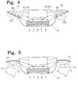
- Fig. 4 shows a cross-section through a third embodiment with an outflow chamber.
- Fig. 5 shows a cross-section through a fourth embodiment which is combined with an illumination device.
- Fig. 6 shows a cross-section through a fifth embodiment provided with insulation material.
- the device to be arranged at a ceiling is constituted by a supply air baffle 1, which may be mounted in a ceiling structure (not shown) or may hang freely below the ceiling of a room, which is to be ventilated, heated and possibly also cooled during certain time periods or when so desired.
- the room may be an office, a factory or any other room where people will stay for a longer or shorter duration.
- Fig. 2 shows a cross-section of a first embodiment of the device of fig. 1.
- the device comprises an elongated air flow chamber 10, which is substantially box-like and extends along the whole length of the device.
- the air flow chamber 10 is open at its lower side 10a and, in this embodiment, also at its upper side 10b, so that room air can flow vertically through the chamber 10, as illustrated by the arrows in figures 1 and 2.
- supply air channels 11 are disposed, these channels being provided with supply air openings.
- the latter are preferably located at the upper side of the supply air channels 11, so that upwardly directed supply air will flow through the upper side 10b of the air flow chamber 10. See the arrows P2.
- the vertical flow of room air (P1) is reinforced by ejector action.
- the air flow chamber 10 there are also arranged a number of tubes 12, through which a cooling or a heating fluid is circulated. These tubes 12 interact primarily with the recirculated room air (arrows P1). The outflow air, supplied through the channels 11, may likewise be cooled or heated.
- the air flow chamber 10 adjoins to at least one metal panel, in this case two metal panels 13, which are designed and disposed in such a way that the air (P1 and P2) flowing out from the air flow chamber through the outflow opening 10b will flow along the downwardly facing surface 13a of each metal panel.
- the air streams P1 and P2 are heated to a relatively high temperature, this flow along the surfaces 13a will cause the metal panels to obtain an elevated temperature, which in turn causes the surfaces 13 to emit radiating heat downwardly into the room.
- the heated air will cause an indirect heating of the room by way of the metal panels 13 radiating heat downwards.
- the air (the streams P1 and P2) will be cooled somewhat, and these air streams will therefore mix more easily with the ambient room air.
- Apart from the advantage in supplying heat to the living zone of the room there will also be an increased content of fresh air in the room (from the supply air channels 11).
- the air flow chamber is designed substantially in the same manner, in its central portion, as the air conditioning device disclosed in SE-0003246-6.
- the ceiling baffle 1 is here provided with an upper supply air channel 11 with downwardly disposed supply air openings 11a and a lower cooling/heating element equipped with tubes 12 for a circulating cooling or heating fluid.
- the ceiling baffle 1 also has outflow openings 10c located between upper and lower side flanges 11b,12b, so that the air streams P1, P2 flow substantially sideways adjacent to the respective metal panel 13.
- the metal panels 13 are arranged sideways at mutual distance and adjoining each upper side flange 11b, respectively.
- the metal panels 13 are substantially arcuate in cross-section (according to figure 3), so that the air streams P1,P2, which flow substantially in parallel to the lower surfaces 13a of the metal panels 13, will follow these lower surfaces.
- the air streams P1,P2 When flowing out from the chamber 10 (at the air flow openings 10c), the air streams P1,P2 are directed obliquely upwards, whereupon they are directed obliquely downwards when they leave the respective metal panel, as indicated by the arrows P3, after having been deflected along the arcuate metal panels.
- the mixing of the air streams with the room air will be facilitated.
- the metal panels 13 also have flanges 13f extending sideways (in parallel with the air flow) and enlarging the effective area of the metal panels 13, so that the heat exchange between the air streams P1,P2 and the metal panels 13 is improved.
- the air flow chamber 10 is designed in the same way as in figure 3, but the laterally adjoining metal panels 13 are in this case disposed as a lower wall of an air outflow box.
- the metal panels 13 have longitudinally distributed openings, slots or perforations 13b, through which the air streams P1,P2 flow out sideways or obliquely sideways. See the arrows P4. Even in this case, the metal panels 13 are heated by the warm air streams and will emit heat radiation downwards to the room.
- the embodiment according to figure 5 corresponds substantially to the embodiment of figure 3 in respect of air flow and thermal characteristics.
- the metal panels 13 have an additional function, namely as a reflector to a light source 15, so that the light source 15 and the arcuately bent metal panel 13 together form an illumination device.
- the lines L depict light rays.
- the metal panels serving as a reflector may be, e.g., circularly cylindrically curved, but it is of course also possible to give the metal panels 13 a different geometrical configuration, if so desired from an optical point of view.
- FIG 6 there is shown a schematic, simple embodiment with substantially planar, horizontal metal panels 13 on each side of the air flow chamber 10.
- a heat insulating material 16 is disposed above the air flow chamber 10 and the two metal panels 13.
- such an insulating material is arranged also in the preceding embodiments, although this is not shown in the drawing figures.
- the metal panels are provided with perforation holes 13c for the absorption of sound.
- the ceiling baffle 1 serves as a supply air device and cooling device at daytime. At night, when the heat generating apparatuses are switched off, there is a need for heat supply. This will be accomplished by circulating hot water through the tubes 12, whereby the room air will be heated as well as the metal panels 13. Now, the supply air in the supply air channel 11 can be cut off, if so desired, by switching of centrally disposed fans.
- the invention can be applied in many ways within the scope of the invention as defined in the claims.
- the shape of the air flow chamber can be modified by those skilled in art.
- the device can be provided with heating elements only.
- the configuration of the metal panels may also be varied.
- the chamber may have an outlet opening at one side only.
- the term "metal panel" also incorporates mixed or composite materials having a good heat conductive capacity. It is essential that the panels 13 have the capacity of accumulating heat from the outflowing air and emitting heat radiation downwardly to the room.
Landscapes
- Engineering & Computer Science (AREA)
- Chemical & Material Sciences (AREA)
- Combustion & Propulsion (AREA)
- Mechanical Engineering (AREA)
- General Engineering & Computer Science (AREA)
- Physics & Mathematics (AREA)
- Thermal Sciences (AREA)
- Life Sciences & Earth Sciences (AREA)
- Sustainable Development (AREA)
- Devices For Blowing Cold Air, Devices For Blowing Warm Air, And Means For Preventing Water Condensation In Air Conditioning Units (AREA)
- Central Heating Systems (AREA)
- Duct Arrangements (AREA)
Applications Claiming Priority (2)
| Application Number | Priority Date | Filing Date | Title |
|---|---|---|---|
| SE0104123A SE523648C2 (sv) | 2001-12-07 | 2001-12-07 | Tilluftbaffel för placering invid ett rumstak för tillförsel av luft till ett rum |
| SE0104123 | 2001-12-07 |
Publications (1)
| Publication Number | Publication Date |
|---|---|
| EP1319902A1 true EP1319902A1 (de) | 2003-06-18 |
Family
ID=20286241
Family Applications (1)
| Application Number | Title | Priority Date | Filing Date |
|---|---|---|---|
| EP02445162A Withdrawn EP1319902A1 (de) | 2001-12-07 | 2002-11-29 | Heizeinrichtung zur Deckenmontage |
Country Status (3)
| Country | Link |
|---|---|
| EP (1) | EP1319902A1 (de) |
| NO (1) | NO20025889L (de) |
| SE (1) | SE523648C2 (de) |
Cited By (4)
| Publication number | Priority date | Publication date | Assignee | Title |
|---|---|---|---|---|
| GB2415247B (en) * | 2004-06-18 | 2009-08-05 | Halton Oy | Supply air terminal device |
| WO2011073525A1 (en) * | 2009-12-18 | 2011-06-23 | Halton Oy | Supply air unit |
| EP2244021A3 (de) * | 2009-04-13 | 2012-04-11 | Kimura Kohki Co., Ltd. | Heiz- und Kühleinheit sowie Heiz- und Kühlvorrichtung |
| EP2535649A3 (de) * | 2011-05-20 | 2014-06-11 | Frenger Systems Limited | Verbesserung bei oder im Zusammenhang mit Klimaanlagenmodulen |
Citations (8)
| Publication number | Priority date | Publication date | Assignee | Title |
|---|---|---|---|---|
| US1492750A (en) * | 1919-09-18 | 1924-05-06 | Charles L Rogers | Air-distributing means |
| DE9315709U1 (de) * | 1993-06-07 | 1994-02-10 | ZENT - FRENGER - Strahlungsheizungs-Gesellschaft mbH, 64646 Heppenheim | Deckenprofil für eine Kühldecke und Kühldecke |
| US5363908A (en) * | 1990-02-24 | 1994-11-15 | Koester Helmut | Heating and cooling arrangement in particular of a structure suspended from a room ceiling |
| WO1995019528A1 (en) * | 1994-01-17 | 1995-07-20 | ABB Fläkt AB | Method of ventilating/conditioning a room and apparatus for performing said method |
| EP0967444A2 (de) * | 1998-06-23 | 1999-12-29 | Stifab Farex AB | Vorrichtung zum Belüften, Kühlen und/oder Beheizen eines Raumes |
| EP0967443A2 (de) | 1998-06-23 | 1999-12-29 | Stifab Farex AB | Luftkühlungsanordnung eines Raumes |
| GB2349688A (en) * | 1999-02-19 | 2000-11-08 | Halton Oy | Air supply device with removable diffuser assembly |
| DE20113303U1 (de) * | 2000-08-18 | 2001-11-15 | Abb Installaatiot Oy, Helsinki | Einrichtung zum Anordnen von technischen Funktionen eines Zimmerraums |
-
2001
- 2001-12-07 SE SE0104123A patent/SE523648C2/sv not_active IP Right Cessation
-
2002
- 2002-11-29 EP EP02445162A patent/EP1319902A1/de not_active Withdrawn
- 2002-12-06 NO NO20025889A patent/NO20025889L/no not_active Application Discontinuation
Patent Citations (8)
| Publication number | Priority date | Publication date | Assignee | Title |
|---|---|---|---|---|
| US1492750A (en) * | 1919-09-18 | 1924-05-06 | Charles L Rogers | Air-distributing means |
| US5363908A (en) * | 1990-02-24 | 1994-11-15 | Koester Helmut | Heating and cooling arrangement in particular of a structure suspended from a room ceiling |
| DE9315709U1 (de) * | 1993-06-07 | 1994-02-10 | ZENT - FRENGER - Strahlungsheizungs-Gesellschaft mbH, 64646 Heppenheim | Deckenprofil für eine Kühldecke und Kühldecke |
| WO1995019528A1 (en) * | 1994-01-17 | 1995-07-20 | ABB Fläkt AB | Method of ventilating/conditioning a room and apparatus for performing said method |
| EP0967444A2 (de) * | 1998-06-23 | 1999-12-29 | Stifab Farex AB | Vorrichtung zum Belüften, Kühlen und/oder Beheizen eines Raumes |
| EP0967443A2 (de) | 1998-06-23 | 1999-12-29 | Stifab Farex AB | Luftkühlungsanordnung eines Raumes |
| GB2349688A (en) * | 1999-02-19 | 2000-11-08 | Halton Oy | Air supply device with removable diffuser assembly |
| DE20113303U1 (de) * | 2000-08-18 | 2001-11-15 | Abb Installaatiot Oy, Helsinki | Einrichtung zum Anordnen von technischen Funktionen eines Zimmerraums |
Cited By (7)
| Publication number | Priority date | Publication date | Assignee | Title |
|---|---|---|---|---|
| GB2415247B (en) * | 2004-06-18 | 2009-08-05 | Halton Oy | Supply air terminal device |
| EP2244021A3 (de) * | 2009-04-13 | 2012-04-11 | Kimura Kohki Co., Ltd. | Heiz- und Kühleinheit sowie Heiz- und Kühlvorrichtung |
| US8844608B2 (en) | 2009-04-13 | 2014-09-30 | Kimura Kohki Co., Ltd. | Heating and cooling unit, and heating and cooling apparatus |
| WO2011073525A1 (en) * | 2009-12-18 | 2011-06-23 | Halton Oy | Supply air unit |
| EP2535649A3 (de) * | 2011-05-20 | 2014-06-11 | Frenger Systems Limited | Verbesserung bei oder im Zusammenhang mit Klimaanlagenmodulen |
| GB2491039B (en) * | 2011-05-20 | 2017-02-01 | Frenger Systems Ltd | Improvements in or relating to air conditioning modules |
| GB2492310B (en) * | 2011-05-20 | 2017-03-01 | Frenger Systems Ltd | Improvements in or relating to air conditioning modules |
Also Published As
| Publication number | Publication date |
|---|---|
| SE523648C2 (sv) | 2004-05-04 |
| NO20025889D0 (no) | 2002-12-06 |
| SE0104123L (sv) | 2003-06-08 |
| SE0104123D0 (sv) | 2001-12-07 |
| NO20025889L (no) | 2003-06-10 |
Similar Documents
| Publication | Publication Date | Title |
|---|---|---|
| JP4999944B2 (ja) | 誘引放射空調機 | |
| AU2010201383B9 (en) | Heating and cooling unit, and heating and cooling apparatus | |
| KR101535866B1 (ko) | 공기 조화 장치 및 공기 조화 장치의 운전 방법 | |
| US20110143648A1 (en) | Automatic displacement ventilation system with heating mode | |
| US6267666B1 (en) | Room air conditioning method and an air-conditioned ceiling for a method of this type | |
| US6438322B1 (en) | Ceiling fan with attached heater and secondary fan | |
| KR20120101354A (ko) | 실내 공기 조화 장치 및 이 장치에 사용되는 히트 펌프 유닛 | |
| JP2011021808A (ja) | 空気式輻射層流ユニット | |
| JP5043158B2 (ja) | 空気熱源ヒートポンプ式空調装置 | |
| EP1319902A1 (de) | Heizeinrichtung zur Deckenmontage | |
| JP4605759B2 (ja) | 建物の室内空調システム | |
| JP2004197988A (ja) | 冷暖房装置 | |
| US20080226452A1 (en) | Modular fan housing | |
| JP7015645B2 (ja) | 空調システム | |
| JP2007271250A (ja) | 輻射空調ユニット | |
| JP4698204B2 (ja) | 建物の室内空調システム | |
| CN101636623B (zh) | 高效率混合空调系统 | |
| US20120088445A1 (en) | Air distribution unit | |
| US20060211361A1 (en) | Personalized air conditioning displacement ventilation system | |
| JP6963912B2 (ja) | ダクト空調・照明一体型システム | |
| US20240369244A1 (en) | Aeraulic device and radiant ceiling thermal system with internal air mixing | |
| JP2005188823A (ja) | 床下暖房装置、及び建物 | |
| JP4503621B2 (ja) | 給気チャンバ | |
| NL2003188C2 (nl) | Constructie-element. | |
| EP2417401B1 (de) | Luftzufuhrvorrichtung |
Legal Events
| Date | Code | Title | Description |
|---|---|---|---|
| PUAI | Public reference made under article 153(3) epc to a published international application that has entered the european phase |
Free format text: ORIGINAL CODE: 0009012 |
|
| AK | Designated contracting states |
Designated state(s): AT BE BG CH CY CZ DE DK EE ES FI FR GB GR IE IT LI LU MC NL PT SE SK TR |
|
| AX | Request for extension of the european patent |
Extension state: AL LT LV MK RO SI |
|
| 17P | Request for examination filed |
Effective date: 20031211 |
|
| AKX | Designation fees paid |
Designated state(s): AT BE BG CH CY CZ DE DK EE ES FI FR GB GR IE IT LI LU MC NL PT SE SK TR |
|
| 17Q | First examination report despatched |
Effective date: 20040401 |
|
| STAA | Information on the status of an ep patent application or granted ep patent |
Free format text: STATUS: THE APPLICATION IS DEEMED TO BE WITHDRAWN |
|
| 18D | Application deemed to be withdrawn |
Effective date: 20040812 |