EP0967627B1 - Elément fusible à plusieurs électrodes et fusible à plusieurs électrodes l' utilisant - Google Patents
Elément fusible à plusieurs électrodes et fusible à plusieurs électrodes l' utilisant Download PDFInfo
- Publication number
- EP0967627B1 EP0967627B1 EP98305027A EP98305027A EP0967627B1 EP 0967627 B1 EP0967627 B1 EP 0967627B1 EP 98305027 A EP98305027 A EP 98305027A EP 98305027 A EP98305027 A EP 98305027A EP 0967627 B1 EP0967627 B1 EP 0967627B1
- Authority
- EP
- European Patent Office
- Prior art keywords
- input terminal
- type fuse
- fuse element
- fuse
- multielectrode
- Prior art date
- Legal status (The legal status is an assumption and is not a legal conclusion. Google has not performed a legal analysis and makes no representation as to the accuracy of the status listed.)
- Expired - Lifetime
Links
- 239000000463 material Substances 0.000 claims description 16
- 230000001419 dependent effect Effects 0.000 claims description 2
- 238000004080 punching Methods 0.000 description 11
- 239000002184 metal Substances 0.000 description 5
- 238000000034 method Methods 0.000 description 3
- 230000008878 coupling Effects 0.000 description 2
- 238000010168 coupling process Methods 0.000 description 2
- 238000005859 coupling reaction Methods 0.000 description 2
- 230000002708 enhancing effect Effects 0.000 description 1
Images




Classifications
-
- H—ELECTRICITY
- H01—ELECTRIC ELEMENTS
- H01H—ELECTRIC SWITCHES; RELAYS; SELECTORS; EMERGENCY PROTECTIVE DEVICES
- H01H85/00—Protective devices in which the current flows through a part of fusible material and this current is interrupted by displacement of the fusible material when this current becomes excessive
-
- H—ELECTRICITY
- H01—ELECTRIC ELEMENTS
- H01H—ELECTRIC SWITCHES; RELAYS; SELECTORS; EMERGENCY PROTECTIVE DEVICES
- H01H85/00—Protective devices in which the current flows through a part of fusible material and this current is interrupted by displacement of the fusible material when this current becomes excessive
- H01H85/02—Details
- H01H85/04—Fuses, i.e. expendable parts of the protective device, e.g. cartridges
- H01H85/041—Fuses, i.e. expendable parts of the protective device, e.g. cartridges characterised by the type
- H01H85/044—General constructions or structure of low voltage fuses, i.e. below 1000 V, or of fuses where the applicable voltage is not specified
-
- H—ELECTRICITY
- H01—ELECTRIC ELEMENTS
- H01H—ELECTRIC SWITCHES; RELAYS; SELECTORS; EMERGENCY PROTECTIVE DEVICES
- H01H85/00—Protective devices in which the current flows through a part of fusible material and this current is interrupted by displacement of the fusible material when this current becomes excessive
- H01H85/02—Details
- H01H85/04—Fuses, i.e. expendable parts of the protective device, e.g. cartridges
- H01H85/05—Component parts thereof
- H01H85/055—Fusible members
- H01H2085/0555—Input terminal connected to a plurality of output terminals, e.g. multielectrode
-
- Y—GENERAL TAGGING OF NEW TECHNOLOGICAL DEVELOPMENTS; GENERAL TAGGING OF CROSS-SECTIONAL TECHNOLOGIES SPANNING OVER SEVERAL SECTIONS OF THE IPC; TECHNICAL SUBJECTS COVERED BY FORMER USPC CROSS-REFERENCE ART COLLECTIONS [XRACs] AND DIGESTS
- Y10—TECHNICAL SUBJECTS COVERED BY FORMER USPC
- Y10T—TECHNICAL SUBJECTS COVERED BY FORMER US CLASSIFICATION
- Y10T29/00—Metal working
- Y10T29/49—Method of mechanical manufacture
- Y10T29/49002—Electrical device making
- Y10T29/49107—Fuse making
Definitions
- the present invention relates to a blade type multielectrode fuse to be used mainly for automobiles which is characterized in that blowout portions and a plurality of terminals are formed integrally by punching from a long fuse material consisting of a single electrically conductive plate.
- a fuse element which is disclosed by U.S. Patent No. 4023264 is conventionally known as a general fuse which is to be disposed in a fuse box for automobiles.
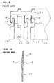
- This fuse element is manufactured by sequentially punching with presses and cutting out from a long fuse material 12 which has a thin portion 11 of definite width formed at in a longitudinal direction at a middle portion thereof into a piece having a predetermined shape and a predetermined length, and configured as a bielectrode type fuse element which has a thin blowout portion 13 between a pair of right and left terminals as shown in FIGS. 7 and 8.
- a reference numeral 10 represents an insulating housing in which the fuse element is to be disposed and fixed.
- a fuse element disclosed by Japanese Patent Publication (KOKOKU) No. 61-14625 is known as a multielectrode type fuse element which is configured to prevent a blown fuse from influencing on other fuses by arranging a plurality of output terminals in parallel with an input terminal on a side of a power source by way of a blowout portion.
- This fuse element is manufactured by punching from a long fuse metal plate material 14, and consists of a common link 16 and a plurality of fuse forming links 17, 17,... which are disposed on one side of a coupling link 15 so that they hang down in parallel with one another, and that they have blowout portions 18 which have sectional areas smaller than those of the other portions as shown in FIGS. 9 and 10.
- the multielectrode type fuse element described above is manufactured by punching from the fuse metal plate 14 which has a definite thickness and projecting a portion 19 from the common link 16, and the links hang down in parallel with one another on one side of (under) the coupling link 15.
- the fuse element disclosed by U.S. Patent No. 4023264 can be manufactured efficiently in a large number by sequentially punching with presses from a long fuse material and cutting into a piece having a predetermined shape and a predetermined length while feeding the long fuse material 12 which has the longitudinal thin area 11 of the definite width in the middle portion thereof, this fuse element is required in a large number for a single vehicle since the fuse element is configured to control electric conduction capacity between an input terminal and output terminals.
- the multielectrode type fuse element disclosed by Japanese Patent Publication (KOKOKU) No. 61-14625 is limited from a viewpoint of working in its width to be pouched since the blowout portions 18 are formed by punching from the fuse metal plate 14 having the definite thickness.
- sectional areas of the blowout portion 18 Since it is required to reduce sectional areas of the blowout portion 18 dependently on electrical conduction capacities, these sectional areas can be adjusted only within a certain limited range by adjusting only a punching width from a plate-like metal which has a definite thickness (0.65mm) required for the fuse links.
- the fuse links are 0.65mm thick and the blowout portions have a sectional area of 0.3mm 2 for 30A (amperes) or 0.1mm 2 for 1A: these blowout portions having sizes from 0.3mm thick by 1.0mm wide to 0.1mm thick by 0.1mm wide.
- EP 0 802 553 A2 discloses a fuse combination in which each fuse comprises an input terminal and an output terminal aligned on opposite sides of a thinned portion, or else a common terminal is provided on one side of respective thinned portions with separate terminals on the other side of the thinned portions.
- a multielectrode type fuse element formed from an elongate electrically conductive plate of fuse material having a thin area, said fuse element comprising:
- the extending portion is hook-like and the output terminals are formed on one side of the input terminal.
- the extending portion is hook-like and output terminals are formed on both sides of the input terminal.
- FIGS. 1 and 2 An embodiment of the present invention will be described with reference to FIGS. 1 and 2.
- a reference numeral 9 represents a long fuse material which consists of an electrically conductive plate and on which a thin area 2 having a definite width is formed in a longitudinal direction at a location a little shifted upward from a center in a width direction with shallow shaving portions 1 tormed by cutting both surfaces.
- This thin area 2 may be provided by cutting both front and rear surfaces so as to form the shallow shaving portions 1, 1 as shown in FIG. 2 or one surface only, and a thickness of the thin are 2 is determined in association with a punching width of a blowout portion 3 dependently on electrical conduction capacities of fuses.
- the multielectrode type fuse element according to the present invention is punched sequentially, as shown in FIG. 1, with presses in a process to transfer the long fuse material 9 so that the fuse element has a configuration wherein a hook-like extending portion 6 is formed on one side (right side) across the thin area 2 at an upper end of an input terminal 4 which is disposed in a direction perpendicular to the longitudinal direction of the long fuse material 9 and blowout portions 3, 3 are formed to connect one side (right side) of an upper portion of a vertical section of the input terminal 4 and a lower tip of the hook-like extending portion 6 with top ends of a plurality of output terminals 5, 5 which are arranged in parallel with the input terminal 4 at an equal pitch.
- blowout portions 3, 3 are positioned so as to be located on the thin area 2.
- a reference numeral 7 represent a punched hole which is to be used for engagement at a stage to insert the multielectrode type fuse element into an insulating housing and caulk it.
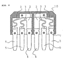
- FIG. 3 shows a fuse element in which output terminals 5, 5 of the fuse element having the shape shown in FIG. 1 are arranged also on a left side of an input terminal 4 symmetrically and integrally. It is possible to sequentially punch fuse elements having this shape with presses in the process to transfer the long fuse material 9.
- a T-shaped extending portion 6' is formed at an upper end of the input terminal 4 located at the center across the thin area 2, and the plurality of output terminals 5, 5 which are arranged on the right and left sides of the input terminal 4 and the input terminal 4 are formed in parallel with one another at a constant pitch, and blowout portions 3, 3 are formed to connect both sides of an upper portion of a vertical section of the input terminal 4 and lower tips on both sides of the T-shaped extending portion 6' with top ends of the plurality of output terminals 5, 5 on both sides.
- FIGS. 4 and 5 are a front view of a longitudinal section illustrating a condition where the upper half of the fuse element having the shape shown in FIG. 3 is disposed and fixed' in an. insulating housing 10, and a side view of a longitudinal section of the middle part or a condition where the multielectrode type fuse is actually used.
- FIG. 6 is a front view of a longitudinal section illustrating a condition where the upper half of two fuse elements which have the shape shown in FIG. 1 is disposed and fixed in an insulating housing 10 with the input terminals 4, 4 adjacent to each other.
- the multielectrode type fuse element according to the present invention can easily be manufactured simply by punching and cutting in a predetermined shape from the long fuse material since the thin area 2 having the definite width can be preliminarily formed over an entire length of the long fuse material in the longitudinal direction thereof.
- the multielectrode type fuse element according to the present invention in which the thin area is preliminarily formed as blowout portions can be punched so as to have a large width, thereby facilitating to adjust a sectional area of the blowout portion and enhancing design freedom.
- the multielectrode type fuse element according to the present invention in which a plurality of output terminals are equipped with blowout portions respectively has fuse functions for a plurality of circuits, thereby making it possible to configure a set of fuses as a whole more compact and lighter in weight.
- the multielectrode type fuse element according to the present invention makes it possible to configure a fuse box more compact and lighter in weight, and features high industrial utility.
Landscapes
- Fuses (AREA)
Claims (5)
- Elément fusible du type à électrodes multiples formé à partir d'une plaque allongée, électriquement conductrice (9) constituée d'un matériau fusible et comportant une zone mince (2), ledit élément fusible comprenant:caractérisé en ce que:une borne d'entrée (4) et au moins des première et seconde bornes de sortie (5), ladite borne d'entrée et lesdites bornes de sortie étant parallèles en étant séparées par un pas identique et s'étendant perpendiculairement à la direction longitudinale de ladite plaque électriquement conductrice (9);une partie étendue (6, 6') qui, en combinaison avec ladite borne d'entrée, constitue une forme de crochet ou une forme en T qui s'étend parallèlement à ladite direction longitudinale; etau moins des première et seconde parties de claquage ou de fusion (3) situées dans ladite zone mince et possédant des largeurs prédéterminées en fonction de la capacité de conduction électrique dudit fusible;lesdites bornes d'entrée et de sortie (4, 5) s'étendent à partir d'un premier côté de ladite zone mince (2) et ladite partie étendue s'étend le long d'un second côté de ladite zone mince, à l'opposé dudit premier côté;une extrémité supérieure de ladite borne d'entrée (4) s'étend à travers ladite zone mince (2) jusqu'à ladite partie étendue (6, 6');ladite première partie de claquage (3) raccorde une extrémité supérieure de ladite première borne de sortie (5) à un côté de ladite extrémité supérieure de ladite borne d'entrée (4); etladite seconde partie de claquage (3) raccorde une extrémité supérieure de ladite seconde borne de sortie (5) à une pointe inférieure de ladite partie étendue.
- Elément fusible du type à électrodes multiples selon la revendication 1, dans lequel ladite partie étendue (6) combinée à ladite borne d'entrée possède la forme d'un crochet et lesdites bornes de sortie (5) sont formées d'un côté de ladite borne d'entrée (4).
- Fusible du type à électrodes multiples comprenant une paire d'éléments fusibles du type à électrodes multiples selon la revendication 1, dont les moitiés supérieures sont disposées et fixées dans un boítier isolant, tandis que leurs bornes d'entrée (4) sont adjacentes entre elles.
- Elément fusible du type à électrodes multiples selon la revendication 1, dans lequel ladite partie étendue (6') combinée à ladite borne d'entrée possède une forme en T, et des bornes de sortie (5) sont formées des deux côtés de ladite borne d'entrée (4).
- Fusible du type à électrodes multiples comprenant un élément fusible du type à électrodes multiples selon la revendication 4, dont la moitié supérieure est disposée et fixée dans un boítier isolant (10).
Priority Applications (11)
| Application Number | Priority Date | Filing Date | Title |
|---|---|---|---|
| JP9017507A JPH10199396A (ja) | 1997-01-13 | 1997-01-13 | 多極型ヒューズ素子およびこの素子を使用した多極型ヒューズ |
| ES98305027T ES2207797T3 (es) | 1997-01-13 | 1998-06-25 | Elemento de fusible del tipo multielectrodo y fusible del tipo mulielectrodo que lo utiliza. |
| DE69818233T DE69818233T2 (de) | 1998-06-25 | 1998-06-25 | Schmelzelement mit mehreren Elektroden und Schmelzsicherung mit mehreren Elektroden, die dieses verwendet |
| US09/104,430 US5977859A (en) | 1997-01-13 | 1998-06-25 | Multielectrode type fuse element and multielectrode type fuse using the same |
| EP98305027A EP0967627B1 (fr) | 1997-01-13 | 1998-06-25 | Elément fusible à plusieurs électrodes et fusible à plusieurs électrodes l' utilisant |
| RU98112332/09A RU2198448C2 (ru) | 1997-01-13 | 1998-06-26 | Плавкий элемент многоэлектродного типа и плавкий предохранитель многоэлектродного типа (варианты) |
| CA002242220A CA2242220C (fr) | 1997-01-13 | 1998-06-30 | Element de fusible a plusieurs electrodes et fusible a plusieurs electrodes employant cet element |
| TW087110555A TW380271B (en) | 1997-01-13 | 1998-06-30 | Multielectrode type fuse element and multielectrode type fuse using the same |
| KR10-1998-0026708A KR100468633B1 (ko) | 1997-01-13 | 1998-07-03 | 다중전극형 퓨즈 소자 |
| BR9806567-0A BR9806567A (pt) | 1997-01-13 | 1998-07-08 | Elemento fusìvel do tipo de eletrodo múltiplo e fusìvel do tipo de eletrodo múltiplo que usa o mesmo |
| CN98115486A CN1241797A (zh) | 1997-01-13 | 1998-07-09 | 多极型保险丝元件及其应用 |
Applications Claiming Priority (8)
| Application Number | Priority Date | Filing Date | Title |
|---|---|---|---|
| JP9017507A JPH10199396A (ja) | 1997-01-13 | 1997-01-13 | 多極型ヒューズ素子およびこの素子を使用した多極型ヒューズ |
| US09/104,430 US5977859A (en) | 1997-01-13 | 1998-06-25 | Multielectrode type fuse element and multielectrode type fuse using the same |
| EP98305027A EP0967627B1 (fr) | 1997-01-13 | 1998-06-25 | Elément fusible à plusieurs électrodes et fusible à plusieurs électrodes l' utilisant |
| RU98112332/09A RU2198448C2 (ru) | 1997-01-13 | 1998-06-26 | Плавкий элемент многоэлектродного типа и плавкий предохранитель многоэлектродного типа (варианты) |
| CA002242220A CA2242220C (fr) | 1997-01-13 | 1998-06-30 | Element de fusible a plusieurs electrodes et fusible a plusieurs electrodes employant cet element |
| KR10-1998-0026708A KR100468633B1 (ko) | 1997-01-13 | 1998-07-03 | 다중전극형 퓨즈 소자 |
| BR9806567-0A BR9806567A (pt) | 1997-01-13 | 1998-07-08 | Elemento fusìvel do tipo de eletrodo múltiplo e fusìvel do tipo de eletrodo múltiplo que usa o mesmo |
| CN98115486A CN1241797A (zh) | 1997-01-13 | 1998-07-09 | 多极型保险丝元件及其应用 |
Publications (2)
| Publication Number | Publication Date |
|---|---|
| EP0967627A1 EP0967627A1 (fr) | 1999-12-29 |
| EP0967627B1 true EP0967627B1 (fr) | 2003-09-17 |
Family
ID=31982804
Family Applications (1)
| Application Number | Title | Priority Date | Filing Date |
|---|---|---|---|
| EP98305027A Expired - Lifetime EP0967627B1 (fr) | 1997-01-13 | 1998-06-25 | Elément fusible à plusieurs électrodes et fusible à plusieurs électrodes l' utilisant |
Country Status (10)
| Country | Link |
|---|---|
| US (1) | US5977859A (fr) |
| EP (1) | EP0967627B1 (fr) |
| JP (1) | JPH10199396A (fr) |
| KR (1) | KR100468633B1 (fr) |
| CN (1) | CN1241797A (fr) |
| BR (1) | BR9806567A (fr) |
| CA (1) | CA2242220C (fr) |
| ES (1) | ES2207797T3 (fr) |
| RU (1) | RU2198448C2 (fr) |
| TW (1) | TW380271B (fr) |
Cited By (2)
| Publication number | Priority date | Publication date | Assignee | Title |
|---|---|---|---|---|
| DE202011000947U1 (de) | 2011-04-20 | 2011-10-10 | Audio Ohm Di Tonani Caterina & C. S.R.L. | Sicherungsträger für ein Kraftfahrzeug |
| DE102010046840A1 (de) | 2010-09-29 | 2012-03-29 | Audio Ohm Di Tonani Caterina & C. S.R.L. | Flachsicherung und Sicherungsträger |
Families Citing this family (48)
| Publication number | Priority date | Publication date | Assignee | Title |
|---|---|---|---|---|
| EP0939967B1 (fr) * | 1996-11-22 | 2002-01-23 | Audio Ohm di Tonani Caterina E.C. S.N.C. | Dispositif de distribution de courant |
| FR2761204B1 (fr) * | 1997-03-24 | 1999-05-14 | Siemens Automotive Sa | Dispositif de distribution d'energie electrique dans plusieurs circuits alimentes en paralleles, et procede de fabrication de ce dispositif |
| US6456186B1 (en) * | 1999-10-27 | 2002-09-24 | Motorola, Inc. | Multi-terminal fuse device |
| JP3814451B2 (ja) * | 1999-12-03 | 2006-08-30 | 住友電装株式会社 | ヒューズの製造方法 |
| JP2001266733A (ja) * | 2000-03-22 | 2001-09-28 | Yazaki Corp | ヒューズ |
| JP2001283710A (ja) * | 2000-03-31 | 2001-10-12 | Yazaki Corp | ヒューズ |
| JP3815709B2 (ja) * | 2000-03-31 | 2006-08-30 | 矢崎総業株式会社 | ヒューズ |
| EP1182680A1 (fr) * | 2000-08-25 | 2002-02-27 | Sumitomo Wiring Systems, Ltd. | Fusible et boítier de connexion électrique |
| TW467389U (en) * | 2000-10-26 | 2001-12-01 | Jonie Chou | Circuit to display the abnormality of three-phase surge absorber of utility power and multi-terminal fuse |
| CN100365901C (zh) * | 2000-11-07 | 2008-01-30 | 周义雄 | 可显示市电三相突波吸收器异常的电路 |
| US6558198B2 (en) * | 2000-11-30 | 2003-05-06 | Autonetworks Technologies, Ltd. | Fuse device and fuse device connecting structure |
| JP2002329453A (ja) * | 2001-04-27 | 2002-11-15 | Yazaki Corp | 連鎖型ヒューズ組立体およびそのレイアウト方法 |
| JP4731721B2 (ja) * | 2001-05-22 | 2011-07-27 | 太平洋精工株式会社 | ヒューズ機構付きジョイントコネクタ |
| ES2393545T3 (es) * | 2001-08-07 | 2012-12-26 | Pacific Engineering Corporation | Composición de resina de poliamida para elemento fusible y elemento fusible |
| JP4009515B2 (ja) * | 2002-10-02 | 2007-11-14 | 矢崎総業株式会社 | ヒュージブルリンクユニット |
| JP2004127698A (ja) * | 2002-10-02 | 2004-04-22 | Yazaki Corp | ヒュージブルリンクユニット |
| JP3737080B2 (ja) * | 2002-11-29 | 2006-01-18 | 山田電機製造株式会社 | 単相誘導電動機の起動装置、起動装置を用いた密閉形電動圧縮機及びこれを用いる機器 |
| KR20050085204A (ko) * | 2002-11-29 | 2005-08-29 | 야마다덴키세이조가부시키가이샤 | 단상유도전동기의 기동장치 |
| USD567766S1 (en) | 2004-11-30 | 2008-04-29 | Pacific Engineering Corp. | Fuse |
| USD555600S1 (en) * | 2004-11-30 | 2007-11-20 | Pacific Engineering Corp. | Fuse |
| USD551174S1 (en) * | 2005-09-30 | 2007-09-18 | Pacific Engineering Corp. | Fuse |
| USD550631S1 (en) * | 2005-10-11 | 2007-09-11 | Pacific Engineering Corp. | Fuse |
| DE102006024391A1 (de) * | 2006-05-24 | 2007-11-29 | Lisa Dräxlmaier GmbH | Sicherungseinheit |
| JP4805057B2 (ja) * | 2006-08-04 | 2011-11-02 | 矢崎総業株式会社 | ヒュージブルリンクユニット |
| US7568921B2 (en) * | 2006-08-22 | 2009-08-04 | Lear Corporation | Fuse cassette |
| DE102006040824B4 (de) * | 2006-08-31 | 2013-03-28 | Lisa Dräxlmaier GmbH | Stromverteiler zum Ausgleichen einer Toleranz |
| USD559203S1 (en) | 2006-11-14 | 2008-01-08 | Littelfuse, Inc. | Indicator for a fuse |
| US20080224814A1 (en) * | 2007-03-13 | 2008-09-18 | Lear Corporation | Electrical assembly and manufacturing method |
| JP4917927B2 (ja) * | 2007-03-15 | 2012-04-18 | 太平洋精工株式会社 | 車両用多連型ヒューズ装置 |
| US7983024B2 (en) * | 2007-04-24 | 2011-07-19 | Littelfuse, Inc. | Fuse card system for automotive circuit protection |
| USD575746S1 (en) | 2008-01-14 | 2008-08-26 | Littelfuse, Inc. | Blade fuse and fuse element therefore |
| US8077007B2 (en) | 2008-01-14 | 2011-12-13 | Littlelfuse, Inc. | Blade fuse |
| USD575745S1 (en) | 2008-01-14 | 2008-08-26 | Littelfuse, Inc. | Blade fuse and fuse element therefore |
| BRPI0801195A2 (pt) * | 2008-04-14 | 2009-12-29 | Sensata Technologies Ltda | dispositivo protetor de sobrecarga de motor, dispositivo para partida de motor, elemento protetor reserva e processo para obtenção de um elemento protetor reserva |
| KR20090112390A (ko) * | 2008-04-24 | 2009-10-28 | 삼성전자주식회사 | 전기적 퓨즈 소자 |
| JP5207533B2 (ja) * | 2008-09-05 | 2013-06-12 | 矢崎総業株式会社 | 複合型ヒュージブルリンク、ヒューズボックス及びその製造方法 |
| JP5486853B2 (ja) * | 2009-06-29 | 2014-05-07 | 矢崎総業株式会社 | ヒュージブルリンクユニット |
| JP5682067B2 (ja) * | 2011-03-31 | 2015-03-11 | 矢崎総業株式会社 | ヒュージブルリンクブロックの回路構成用バスバー、ヒュージブルリンクブロック、およびヒュージブルリンクブロックの製造方法 |
| JP5771057B2 (ja) | 2011-04-22 | 2015-08-26 | 矢崎総業株式会社 | ヒューズ |
| JP5695975B2 (ja) * | 2011-05-26 | 2015-04-08 | 矢崎総業株式会社 | ヒュージブルリンク装着構造及び電気接続箱 |
| JP6255158B2 (ja) * | 2013-02-12 | 2017-12-27 | 矢崎総業株式会社 | バスバー |
| JP5903399B2 (ja) * | 2013-04-17 | 2016-04-13 | 太平洋精工株式会社 | 多極型ヒュージブルリンク |
| CN105103260B (zh) * | 2013-04-17 | 2018-03-16 | 太平洋精工株式会社 | 多极熔断线 |
| CN108289372B (zh) * | 2017-01-09 | 2021-11-19 | 莫仕连接器(成都)有限公司 | 电池连接模块 |
| JP7578028B2 (ja) * | 2021-03-09 | 2024-11-06 | 株式会社オートネットワーク技術研究所 | 回路装置 |
| US12525671B2 (en) | 2023-06-30 | 2026-01-13 | Rivian Ip Holdings, Llc | Battery welds |
| US12542330B2 (en) | 2023-06-30 | 2026-02-03 | Rivian Ip Holdings, Llc | Battery subassembly with potting material |
| US12471245B2 (en) | 2023-06-30 | 2025-11-11 | Rivian Ip Holdings, Llc | Cold plate |
Family Cites Families (22)
| Publication number | Priority date | Publication date | Assignee | Title |
|---|---|---|---|---|
| JPS5118946A (en) * | 1974-08-08 | 1976-02-14 | Yamazaki Denki Kogyo Kk | Tetsukokinzokuno gasushinhoho |
| US4023265A (en) * | 1975-12-12 | 1977-05-17 | Littelfuse, Inc. | Method of making a miniature plug-in fuse |
| JPS5286148A (en) * | 1976-01-13 | 1977-07-18 | Shinagawa Jidosha Densen | Fuse board |
| US4023264A (en) * | 1976-06-21 | 1977-05-17 | Littelfuse, Inc. | Method of making miniature plug-in fuses of different fuse ratings |
| JPS5717049A (en) * | 1980-07-04 | 1982-01-28 | Hitachi Ltd | Direct memory access controlling circuit and data processing system |
| DE3044040A1 (de) * | 1980-11-22 | 1982-07-15 | Wilhelm Pudenz KG, 2833 Dünsen | Stecksicherung |
| JPS5827966A (ja) * | 1981-08-12 | 1983-02-18 | Nippon Mining Co Ltd | 高力導電銅合金の熱処理方法 |
| JPS6114625A (ja) * | 1984-06-29 | 1986-01-22 | Canon Inc | フイルムコマ数表示装置 |
| US4604602A (en) * | 1984-08-17 | 1986-08-05 | Littelfuse, Inc. | Plug-in fuse assembly with stackable housing |
| JPH0724053B2 (ja) * | 1985-08-01 | 1995-03-15 | カシオ計算機株式会社 | 仮名漢字変換装置 |
| US4689597A (en) * | 1986-04-29 | 1987-08-25 | Amp Incorporated | Electrical fuse component and method of using same |
| US4831353A (en) * | 1987-09-30 | 1989-05-16 | Cooper Industries, Inc. | Cable fuse |
| GB2233840B (en) * | 1989-04-24 | 1994-05-11 | Cooper Ind Inc | Electrical fuse |
| JPH03285230A (ja) * | 1990-03-30 | 1991-12-16 | Sumitomo Electric Ind Ltd | 非可逆可変色ヒューズ |
| US5055817A (en) * | 1990-10-03 | 1991-10-08 | Gould Inc. | Fuse with improved fusible element |
| WO1992013356A1 (fr) * | 1991-01-16 | 1992-08-06 | Dav | Fusible plat pour courants nominaux eleves |
| US5229739A (en) * | 1992-02-21 | 1993-07-20 | Littelfuse, Inc. | Automotive high current fuse |
| JPH07105826A (ja) * | 1993-09-30 | 1995-04-21 | Shusaku Umeda | ヒューズ、ヒューズ箱及び感温弁 |
| JP3442159B2 (ja) * | 1994-09-27 | 2003-09-02 | 矢崎総業株式会社 | ヒューズ |
| JPH09282999A (ja) * | 1996-04-17 | 1997-10-31 | Sumitomo Wiring Syst Ltd | ヒューズ素子とその製造方法及びヒューズ装置 |
| US6007350A (en) * | 1996-09-12 | 1999-12-28 | Sumitomo Wiring Systems, Ltd. | Electrical connection box |
| GB2326287B (en) * | 1997-06-09 | 2001-10-24 | Delphi Automotive Systems Gmbh | Fuse assembly |
-
1997
- 1997-01-13 JP JP9017507A patent/JPH10199396A/ja active Pending
-
1998
- 1998-06-25 US US09/104,430 patent/US5977859A/en not_active Expired - Lifetime
- 1998-06-25 EP EP98305027A patent/EP0967627B1/fr not_active Expired - Lifetime
- 1998-06-25 ES ES98305027T patent/ES2207797T3/es not_active Expired - Lifetime
- 1998-06-26 RU RU98112332/09A patent/RU2198448C2/ru not_active IP Right Cessation
- 1998-06-30 CA CA002242220A patent/CA2242220C/fr not_active Expired - Fee Related
- 1998-06-30 TW TW087110555A patent/TW380271B/zh not_active IP Right Cessation
- 1998-07-03 KR KR10-1998-0026708A patent/KR100468633B1/ko not_active Expired - Lifetime
- 1998-07-08 BR BR9806567-0A patent/BR9806567A/pt active Search and Examination
- 1998-07-09 CN CN98115486A patent/CN1241797A/zh active Pending
Cited By (3)
| Publication number | Priority date | Publication date | Assignee | Title |
|---|---|---|---|---|
| DE102010046840A1 (de) | 2010-09-29 | 2012-03-29 | Audio Ohm Di Tonani Caterina & C. S.R.L. | Flachsicherung und Sicherungsträger |
| DE102010046840B4 (de) * | 2010-09-29 | 2013-10-10 | Audio Ohm Di Tonani Caterina & C. S.R.L. | Flachsicherung und Sicherungsträger |
| DE202011000947U1 (de) | 2011-04-20 | 2011-10-10 | Audio Ohm Di Tonani Caterina & C. S.R.L. | Sicherungsträger für ein Kraftfahrzeug |
Also Published As
| Publication number | Publication date |
|---|---|
| RU2198448C2 (ru) | 2003-02-10 |
| CA2242220A1 (fr) | 1999-12-30 |
| KR100468633B1 (ko) | 2005-04-06 |
| CN1241797A (zh) | 2000-01-19 |
| ES2207797T3 (es) | 2004-06-01 |
| TW380271B (en) | 2000-01-21 |
| BR9806567A (pt) | 2000-07-11 |
| EP0967627A1 (fr) | 1999-12-29 |
| US5977859A (en) | 1999-11-02 |
| KR20000007398A (ko) | 2000-02-07 |
| JPH10199396A (ja) | 1998-07-31 |
| CA2242220C (fr) | 2005-10-04 |
Similar Documents
| Publication | Publication Date | Title |
|---|---|---|
| EP0967627B1 (fr) | Elément fusible à plusieurs électrodes et fusible à plusieurs électrodes l' utilisant | |
| EP1253613B1 (fr) | Ensemble à élément fusible et procédé d' agencement relatif | |
| US5395252A (en) | Area and edge array electrical connectors | |
| US5581225A (en) | One-piece female blade fuse with housing | |
| US6921301B2 (en) | Blade-contact socket | |
| EP0703117B1 (fr) | Boíte de connexion électrique | |
| DE60128716T2 (de) | Klingensicherung | |
| EP1065768B1 (fr) | Structure de connexion des barres omnibus | |
| RU98112332A (ru) | Плавкий элемент многоэлектродного типа и плавкий предохранитель многоэлектродного типа (варианты) | |
| JPH0230136B2 (fr) | ||
| US5123854A (en) | Shunted electrical connector | |
| US20010027042A1 (en) | Terminal with link strip | |
| EP0767479B1 (fr) | Elément fusible pour fusible lent | |
| EP1148531B1 (fr) | Fusible | |
| US5372521A (en) | Electrical connection bar for terminals | |
| JPH10199395A (ja) | 多極型ヒューズ素子およびこの素子を使用した多極型ヒューズ | |
| US6531949B2 (en) | Fuse | |
| EP1063725B1 (fr) | Structure de connexion de fils électriques | |
| US4670725A (en) | Relay tongue unit | |
| MXPA98005444A (en) | Fuse element of the type of multi-electrode and fuse of the type of multi-electrode using the anter | |
| JPS6231466B2 (fr) | ||
| US4806121A (en) | Contact socket element, strip comprising it and its manufacturing | |
| JP3141307B2 (ja) | スイッチ接点/コネクター用端子の製造方法 | |
| JP3146950B2 (ja) | 電気接続箱 | |
| US6341977B1 (en) | Pressure-contact terminal |
Legal Events
| Date | Code | Title | Description |
|---|---|---|---|
| PUAI | Public reference made under article 153(3) epc to a published international application that has entered the european phase |
Free format text: ORIGINAL CODE: 0009012 |
|
| 17P | Request for examination filed |
Effective date: 19990510 |
|
| AK | Designated contracting states |
Kind code of ref document: A1 Designated state(s): BE DE ES FR GB IT NL SE |
|
| AX | Request for extension of the european patent |
Free format text: AL;LT;LV;MK;RO;SI |
|
| AKX | Designation fees paid |
Free format text: BE DE ES FR GB IT NL SE |
|
| 17Q | First examination report despatched |
Effective date: 20020603 |
|
| GRAH | Despatch of communication of intention to grant a patent |
Free format text: ORIGINAL CODE: EPIDOS IGRA |
|
| GRAH | Despatch of communication of intention to grant a patent |
Free format text: ORIGINAL CODE: EPIDOS IGRA |
|
| GRAA | (expected) grant |
Free format text: ORIGINAL CODE: 0009210 |
|
| AK | Designated contracting states |
Kind code of ref document: B1 Designated state(s): BE DE ES FR GB IT NL SE |
|
| REG | Reference to a national code |
Ref country code: GB Ref legal event code: FG4D |
|
| REF | Corresponds to: |
Ref document number: 69818233 Country of ref document: DE Date of ref document: 20031023 Kind code of ref document: P |
|
| REG | Reference to a national code |
Ref country code: SE Ref legal event code: TRGR |
|
| REG | Reference to a national code |
Ref country code: ES Ref legal event code: FG2A Ref document number: 2207797 Country of ref document: ES Kind code of ref document: T3 |
|
| ET | Fr: translation filed | ||
| PLBE | No opposition filed within time limit |
Free format text: ORIGINAL CODE: 0009261 |
|
| STAA | Information on the status of an ep patent application or granted ep patent |
Free format text: STATUS: NO OPPOSITION FILED WITHIN TIME LIMIT |
|
| 26N | No opposition filed |
Effective date: 20040618 |
|
| PGFP | Annual fee paid to national office [announced via postgrant information from national office to epo] |
Ref country code: NL Payment date: 20060604 Year of fee payment: 9 |
|
| PGFP | Annual fee paid to national office [announced via postgrant information from national office to epo] |
Ref country code: ES Payment date: 20060720 Year of fee payment: 9 |
|
| PGFP | Annual fee paid to national office [announced via postgrant information from national office to epo] |
Ref country code: BE Payment date: 20060816 Year of fee payment: 9 |
|
| BERE | Be: lapsed |
Owner name: *PACIFIC ENGINEERING CORP. Effective date: 20070630 |
|
| NLV4 | Nl: lapsed or anulled due to non-payment of the annual fee |
Effective date: 20080101 |
|
| PG25 | Lapsed in a contracting state [announced via postgrant information from national office to epo] |
Ref country code: BE Free format text: LAPSE BECAUSE OF NON-PAYMENT OF DUE FEES Effective date: 20070630 |
|
| PG25 | Lapsed in a contracting state [announced via postgrant information from national office to epo] |
Ref country code: NL Free format text: LAPSE BECAUSE OF NON-PAYMENT OF DUE FEES Effective date: 20080101 |
|
| REG | Reference to a national code |
Ref country code: ES Ref legal event code: FD2A Effective date: 20070626 |
|
| PG25 | Lapsed in a contracting state [announced via postgrant information from national office to epo] |
Ref country code: ES Free format text: LAPSE BECAUSE OF NON-PAYMENT OF DUE FEES Effective date: 20070626 |
|
| PGFP | Annual fee paid to national office [announced via postgrant information from national office to epo] |
Ref country code: SE Payment date: 20080609 Year of fee payment: 11 |
|
| PGFP | Annual fee paid to national office [announced via postgrant information from national office to epo] |
Ref country code: FR Payment date: 20080617 Year of fee payment: 11 |
|
| PGFP | Annual fee paid to national office [announced via postgrant information from national office to epo] |
Ref country code: GB Payment date: 20080625 Year of fee payment: 11 |
|
| GBPC | Gb: european patent ceased through non-payment of renewal fee |
Effective date: 20090625 |
|
| REG | Reference to a national code |
Ref country code: FR Ref legal event code: ST Effective date: 20100226 |
|
| PG25 | Lapsed in a contracting state [announced via postgrant information from national office to epo] |
Ref country code: FR Free format text: LAPSE BECAUSE OF NON-PAYMENT OF DUE FEES Effective date: 20090630 |
|
| PG25 | Lapsed in a contracting state [announced via postgrant information from national office to epo] |
Ref country code: GB Free format text: LAPSE BECAUSE OF NON-PAYMENT OF DUE FEES Effective date: 20090625 |
|
| PG25 | Lapsed in a contracting state [announced via postgrant information from national office to epo] |
Ref country code: SE Free format text: LAPSE BECAUSE OF NON-PAYMENT OF DUE FEES Effective date: 20090626 |
|
| PGFP | Annual fee paid to national office [announced via postgrant information from national office to epo] |
Ref country code: IT Payment date: 20170619 Year of fee payment: 20 |
|
| PGFP | Annual fee paid to national office [announced via postgrant information from national office to epo] |
Ref country code: DE Payment date: 20170621 Year of fee payment: 20 |
|
| REG | Reference to a national code |
Ref country code: DE Ref legal event code: R071 Ref document number: 69818233 Country of ref document: DE |