EP0967687A2 - Rétention d'un insert dans un connecteur - Google Patents
Rétention d'un insert dans un connecteur Download PDFInfo
- Publication number
- EP0967687A2 EP0967687A2 EP99111536A EP99111536A EP0967687A2 EP 0967687 A2 EP0967687 A2 EP 0967687A2 EP 99111536 A EP99111536 A EP 99111536A EP 99111536 A EP99111536 A EP 99111536A EP 0967687 A2 EP0967687 A2 EP 0967687A2
- Authority
- EP
- European Patent Office
- Prior art keywords
- tine
- shell
- insert
- section
- forwardly
- Prior art date
- Legal status (The legal status is an assumption and is not a legal conclusion. Google has not performed a legal analysis and makes no representation as to the accuracy of the status listed.)
- Withdrawn
Links
- 230000014759 maintenance of location Effects 0.000 title 1
- 239000002184 metal Substances 0.000 claims abstract description 10
- 239000012212 insulator Substances 0.000 claims abstract description 9
- 238000005452 bending Methods 0.000 claims 1
- 238000000034 method Methods 0.000 claims 1
- 230000000717 retained effect Effects 0.000 abstract 1
- 239000000835 fiber Substances 0.000 description 3
- 230000000712 assembly Effects 0.000 description 2
- 238000000429 assembly Methods 0.000 description 2
- 238000003780 insertion Methods 0.000 description 2
- 230000037431 insertion Effects 0.000 description 2
- 239000000463 material Substances 0.000 description 2
- 238000012986 modification Methods 0.000 description 2
- 230000004048 modification Effects 0.000 description 2
- 239000004020 conductor Substances 0.000 description 1
- 230000000994 depressogenic effect Effects 0.000 description 1
- 239000013307 optical fiber Substances 0.000 description 1
- 229910001220 stainless steel Inorganic materials 0.000 description 1
- 239000010935 stainless steel Substances 0.000 description 1
Images


Classifications
-
- H—ELECTRICITY
- H01—ELECTRIC ELEMENTS
- H01R—ELECTRICALLY-CONDUCTIVE CONNECTIONS; STRUCTURAL ASSOCIATIONS OF A PLURALITY OF MUTUALLY-INSULATED ELECTRICAL CONNECTING ELEMENTS; COUPLING DEVICES; CURRENT COLLECTORS
- H01R13/00—Details of coupling devices of the kinds covered by groups H01R12/70 or H01R24/00 - H01R33/00
- H01R13/46—Bases; Cases
- H01R13/502—Bases; Cases composed of different pieces
- H01R13/508—Bases; Cases composed of different pieces assembled by a separate clip or spring
-
- H—ELECTRICITY
- H01—ELECTRIC ELEMENTS
- H01R—ELECTRICALLY-CONDUCTIVE CONNECTIONS; STRUCTURAL ASSOCIATIONS OF A PLURALITY OF MUTUALLY-INSULATED ELECTRICAL CONNECTING ELEMENTS; COUPLING DEVICES; CURRENT COLLECTORS
- H01R13/00—Details of coupling devices of the kinds covered by groups H01R12/70 or H01R24/00 - H01R33/00
- H01R13/46—Bases; Cases
- H01R13/502—Bases; Cases composed of different pieces
- H01R13/506—Bases; Cases composed of different pieces assembled by snap action of the parts
-
- Y—GENERAL TAGGING OF NEW TECHNOLOGICAL DEVELOPMENTS; GENERAL TAGGING OF CROSS-SECTIONAL TECHNOLOGIES SPANNING OVER SEVERAL SECTIONS OF THE IPC; TECHNICAL SUBJECTS COVERED BY FORMER USPC CROSS-REFERENCE ART COLLECTIONS [XRACs] AND DIGESTS
- Y10—TECHNICAL SUBJECTS COVERED BY FORMER USPC
- Y10S—TECHNICAL SUBJECTS COVERED BY FORMER USPC CROSS-REFERENCE ART COLLECTIONS [XRACs] AND DIGESTS
- Y10S439/00—Electrical connectors
- Y10S439/901—Connector hood or shell
- Y10S439/903—Special latch for insert
Definitions
- Electrical and optic connectors commonly include an insert with a plurality of parallel contact-receiving passages, with the insert received in a shell.
- the insert is commonly inserted forwardly into an open rear of the shell, and is held therein by any of a number of devices, including screws and sidewardly-slideable retainer plates.
- a simple means for retaining an insert in a shell, which facilitated removal of the insulator from the shell when necessary, would be of value.
- a mechanism for retaining a connector insert within a shell, which automatically retains the insert after it has been fully installed, which enables easy and rapid removal, which uses simple sheet metal parts, and which enables rearward removal of the insert by a tool inserted into the rear of the connector.
- the insert is provided with cavities at opposite sides of its rear end.
- the shell is formed with its rear part having a forwardly-facing shoulder on its inside.
- the insert has a cavity facing the shell shoulder, and has a resilient sheet metal tine with a front mount portion fixed to the rest of the insert.
- the tine has a first section extending at a rearward and outward incline from the mount portion so the rear end of the first section lies immediately forward of the shell shoulder.
- the tine also has a second section that extends inwardly along the shell shoulder, and has a tab at the inner end of the second section. The second section substantially abuts the shell shoulder to prevent insert removal. However, when the tab is deflected inwardly by a tool inserted into the cavity at the rear of the connector, the insert can be removed.
- Fig. 1 illustrates a connector 10 which includes a shell 12 and inserts 14, with the figure showing three inserts spaced in a lateral direction L.
- Each insert includes a plurality of contact-holding passages 16 that receive electrical or optic contacts, for connecting to similar contacts of another connector.
- Each of the contacts such as contact 20 has an electrical wire or optical fiber assembly 22 extending in a rearward direction R from the rear end of the insert passage.
- the inserts are designed to be inserted in a forward direction F into the shell.
- a plurality of tines 30, lying at longitudinally M opposite sides of each of the three inserts, serves to retain the corresponding insert in the shell.
- the connector is constructed so the tines 30 can be operated to release a corresponding connector, from the rear end 32 of the shell, which is the end from which the insert is withdrawn from the shell.
- mounting flanges such as indicated at 34 are sometimes provided on shells, for mounting on walls of equipment and release of the tines from the same rearward end out of which the insert is pulled, is desirable especially where there is not ready access to connector locations forward of the mounting flange.
- Fig. 2 illustrates a portion of the connector 10, showing one of the inserts 14 as it is being installed by moving it forwardly F into the shell 12.
- the insert includes an isolator, or insulator 36 and a pair of tines 30.
- the isolator or insulator can be formed of electrically conductive material such as metal.
- Each tine 30 has a forward mount portion 40 that is fixed in position within the insert isolator.
- the tine has a free portion 41 with first and second sections 42, 50 and a tab 52.
- the first section 42 extends at an outward O and rearward R incline from the mount portion 40, with the rear end 44 of the first section extending sidewardly (in direction M) beyond a cavity 46 formed in the insert isolator.
- a primarily rearwardly-facing second section or tine shoulder 50 extends inwardly I from the rear end of the first section, and a tab 52 extends rearwardly from an inner end of the second section 50.
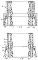
- a surface 54 of the shell deflect the tine inwardly to the position 30A.
- the tine snaps back to its original lock position 30.
- the tine second section shoulder 50 lies directly forward of a shell shoulder 60 that faces primarily forwardly.
- the shell shoulder 60 prevents rearward movement of the insert 14 out of the shell.
- Forwardly-facing surfaces 61 of longitudinally-projecting isolator side projections 63 limit forward movement of the isolator.
- Fig. 4 shows the tine in its release position 30A, which is accomplished by deflecting the tab 52 inwardly.
- deflecting the tab and corresponding deflection of the first and second sections 42, 50 enables the insert 14 to be removed, as by pulling rearwardly on the wires or fiber assemblies extending rearwardly from the insert.
- wires or fiber assemblies extend from the rear of the insert and occupy a region immediately rearward of the contact-holding passages, the rear of the cavity 46 lies at a longitudinal side of the wires and is not covered.
- a side hole indicated at 56 may be provided for insertion of a thin tool to deflect the tine, but applicant generally prefers that the tool be inserted into the rear of the shell, through the rear 62 of the cavity 46, since the rear is open when the insert is removed from the rear of the shell. It is noted that the cavity has an open longitudinally-facing (in outward direction O) cavity side 64, but that is open only to a recess 66 in the shell.
- FIG. 1 shows one example of a tool 70 for deflecting a pair of tabs to remove a connector.
- the tool includes a fixed forwardly-projecting flange 72 and a moveable flange 74 that is moved when a button 76 is depressed against the force of a spring (not shown) to move the tine tabs 52 together.
- a spring not shown
- the mount portion 40 (Fig. 2) of the tine can be fixed in the insert in a number of ways.
- One way is to mold plastic material of the insert isolator 36 around the mount portion 40 of the tine.
- Another way, shown in Fig. 9, is to provide a slot 80 and to slide the mount portion of the tine along the slot into its final position. Then, the mount portion can be trapped by inwardly deflecting locations 82 of the insert material.
- the tine is preferably formed of resilient sheet metal, such as stainless steel sheet metal, which has been plastically deformed to the shape illustrated.
- sheet metal tines can be produced in quantity at low cost and provide high resilience because of their thinness.
- Each tine preferably has a width in a lateral direction L that is at least one-fourth its length in forward-rearward directions F, R, to provide strength against undesirable tine twisting or collapse.
- the illustrated tines each has a width equal to its length.
- the invention provides a connector of the type that includes a shell and an insert that can be removed in a rearward direction from the shell, wherein a simple, low cost and reliable mechanism is provided, that enables release of the insert from the rear of the connector.
- the mechanism includes a resilient tine that is formed of a piece of sheet metal that has been deformed to its shape.
- the tine has a front mount portion that is fixed in the insert isolator, a first section extending at a rearward and outward incline, and a second section extending inwardly from a rear end of the first section, with a tab at the inner end of the second section.
- the shell is formed with a largely forwardly-facing shoulder on its inside, which lies directly rearward of the tine second section, to prevent rearward movement of the tine and therefore of the insert, until the tine is deflected.
Landscapes
- Connector Housings Or Holding Contact Members (AREA)
- Coupling Device And Connection With Printed Circuit (AREA)
- Details Of Connecting Devices For Male And Female Coupling (AREA)
Applications Claiming Priority (2)
| Application Number | Priority Date | Filing Date | Title |
|---|---|---|---|
| US102548 | 1998-06-22 | ||
| US09/102,548 US6042428A (en) | 1998-06-22 | 1998-06-22 | Connector insert retention |
Publications (2)
| Publication Number | Publication Date |
|---|---|
| EP0967687A2 true EP0967687A2 (fr) | 1999-12-29 |
| EP0967687A3 EP0967687A3 (fr) | 2001-04-25 |
Family
ID=22290415
Family Applications (1)
| Application Number | Title | Priority Date | Filing Date |
|---|---|---|---|
| EP99111536A Withdrawn EP0967687A3 (fr) | 1998-06-22 | 1999-06-14 | Rétention d'un insert dans un connecteur |
Country Status (2)
| Country | Link |
|---|---|
| US (1) | US6042428A (fr) |
| EP (1) | EP0967687A3 (fr) |
Cited By (1)
| Publication number | Priority date | Publication date | Assignee | Title |
|---|---|---|---|---|
| EP1122833A1 (fr) * | 2000-02-04 | 2001-08-08 | Air LB International S.A. | Dispositif d'assemblage d'un boítier de connecteur et d'un capot de maintien et de protection des fils raccordés audit connecteur |
Families Citing this family (7)
| Publication number | Priority date | Publication date | Assignee | Title |
|---|---|---|---|---|
| US6363199B1 (en) * | 2000-10-10 | 2002-03-26 | Neptec Optical Solutions, Inc. | Extraction apparatus for a fiber optic connector component |
| US6471414B2 (en) * | 2000-10-10 | 2002-10-29 | Neptec Optical Solutions, Inc. | Spring clip assembly for fiber optic adapter |
| FR2843491B1 (fr) * | 2002-08-09 | 2006-09-08 | Amphenol Air Lb | Connecteur pour des conducteurs electriques comportant un embout de contact et de verrouillage a leur extremite a connecter |
| FR2886475B1 (fr) * | 2005-05-27 | 2011-10-28 | Amphenol Air Lb | Connecteur blinde pour conducteurs electriques. |
| US9444169B2 (en) * | 2015-01-21 | 2016-09-13 | Cooper Technologies Company | Contacts with retractable drive pins |
| DE102016105470A1 (de) * | 2016-03-23 | 2017-09-28 | Te Connectivity Germany Gmbh | Leistungselektrische Kontakteinrichtung; austauschbares, leistungselektrisches Kontaktmodul sowie leistungselektrischer Verbinder |
| CN107329210B (zh) | 2016-04-19 | 2021-03-09 | 西蒙公司 | 通信连接器安装夹 |
Family Cites Families (20)
| Publication number | Priority date | Publication date | Assignee | Title |
|---|---|---|---|---|
| US3570096A (en) * | 1968-04-26 | 1971-03-16 | Thomas & Betts Corp | Module extraction tool |
| US3885849A (en) * | 1973-03-08 | 1975-05-27 | Switchcraft | Electrical connectors with interchangeable components |
| US3993394A (en) * | 1974-07-31 | 1976-11-23 | Raychem Corporation | Connector half having connector wafer retained therein |
| US3951514A (en) * | 1974-12-23 | 1976-04-20 | International Telephone And Telegraph Corporation | Connector member |
| US4084882A (en) * | 1976-08-30 | 1978-04-18 | International Telephone And Telegraph Corporation | Connector member |
| US4193655A (en) * | 1978-07-20 | 1980-03-18 | Amp Incorporated | Field repairable connector assembly |
| US4361376A (en) * | 1980-11-14 | 1982-11-30 | The Bendix Corporation | Electrical connector |
| US4413875A (en) * | 1981-09-23 | 1983-11-08 | Matrix Science Corporation | Connector retaining apparatus |
| US4477022A (en) * | 1982-02-23 | 1984-10-16 | Amp Incorporated | Polarizing and latch arrangement for an electrical connector |
| US4764130A (en) * | 1983-02-07 | 1988-08-16 | Amp Incorporated | Electrical connector having terminal housing retaining member |
| DE3566853D1 (en) * | 1984-06-29 | 1989-01-19 | Amp Inc | Retention article for electrical contacts |
| FR2572857B1 (fr) * | 1984-11-05 | 1986-12-26 | Sogie | Element de connecteur multicontacts et dispositif pour immobiliser un bloc isolant dans le boitier d'un tel element de connecteur |
| US4834678A (en) * | 1988-05-31 | 1989-05-30 | Amp Incorporated | High voltage contact assembly |
| US4985002A (en) * | 1988-10-25 | 1991-01-15 | Preh, Elektrofeinmechanische Werke Jakob Preh, Nachf, Gmbh & Co. | Shielded circular plug connector |
| US4927388A (en) * | 1989-09-29 | 1990-05-22 | Amp Incorporated | Electrical connector shell assembly and module retention clip |
| JPH0770334B2 (ja) * | 1989-12-27 | 1995-07-31 | 矢崎総業株式会社 | 端子係止具付コネクタ |
| DE4216162C2 (de) * | 1991-07-26 | 1996-04-04 | Standard Establishment | Mechanische Verriegelung an einer Steckverbindung zwischen einem elektrischen Schalter und einem Verbindungsstecker |
| US5145411A (en) * | 1991-08-14 | 1992-09-08 | Amp Incorporated | Connector insert retention system |
| JP2518968Y2 (ja) * | 1992-02-06 | 1996-12-04 | 矢崎総業株式会社 | 合体式コネクタ |
| NL1000052C2 (nl) * | 1995-04-05 | 1996-10-08 | Framatome Connectors Belgium | Connector. |
-
1998
- 1998-06-22 US US09/102,548 patent/US6042428A/en not_active Expired - Fee Related
-
1999
- 1999-06-14 EP EP99111536A patent/EP0967687A3/fr not_active Withdrawn
Cited By (2)
| Publication number | Priority date | Publication date | Assignee | Title |
|---|---|---|---|---|
| EP1122833A1 (fr) * | 2000-02-04 | 2001-08-08 | Air LB International S.A. | Dispositif d'assemblage d'un boítier de connecteur et d'un capot de maintien et de protection des fils raccordés audit connecteur |
| FR2804798A1 (fr) * | 2000-02-04 | 2001-08-10 | Air Lb Internat Sa | Dispositif d'assemblage d'un boitier de connecteur et d'un capot de maintien et de protection des fils raccordes audit connecteur |
Also Published As
| Publication number | Publication date |
|---|---|
| EP0967687A3 (fr) | 2001-04-25 |
| US6042428A (en) | 2000-03-28 |
Similar Documents
| Publication | Publication Date | Title |
|---|---|---|
| US6149451A (en) | Cable connector latching device | |
| EP0307464B1 (fr) | Systeme de retenue et de stabilisation de bornes pour connecteur electrique | |
| US5026304A (en) | Connector and connector assembly having improved terminal insertion feature | |
| US5470258A (en) | Electrical connector | |
| EP0830712B1 (fr) | Connecteur electrique | |
| EP0740374A2 (fr) | Système de retenue de contact | |
| WO1998027624A1 (fr) | Verrou a ressort monobloc pour ensemble connecteur electrique | |
| US7892048B2 (en) | Cable end connector and method of assembling the same | |
| US6751392B1 (en) | Cable management system for connector assemblies | |
| US6086419A (en) | Electrical connector assembly | |
| EP0740372B1 (fr) | Connecteur électrique | |
| EP0881711A1 (fr) | Connecteur électrique pour des circuits plats flexibles | |
| US5980283A (en) | Lever-fitting type connector with lever insertion limitation and withdrawal portion | |
| US5133672A (en) | Insulation displacement terminal | |
| EP0356157A2 (fr) | Connecteur électrique ayant un loquet antisurcharge | |
| EP0025366A1 (fr) | Connecteur électrique séparable du type contenant des premiers et seconds membres connecteurs avec des contacts améliorés pour l'un des membres connecteurs | |
| US5389013A (en) | Electrical terminal with means to avoid locking lance damage and entanglement | |
| US6042428A (en) | Connector insert retention | |
| EP0610855B1 (fr) | Connecteur électrique avec dispositif de rétention des contacts | |
| US4295698A (en) | Electrical connector housing | |
| GB2251343A (en) | Double lock connector. | |
| US5427549A (en) | Electrical cable assembly with improved latch | |
| US5672075A (en) | Round terminal-receiving connector | |
| EP0442215A1 (fr) | Ensemble connecteur modulaire assurant soulagement de traction | |
| US5373573A (en) | High density fiber optic connector |
Legal Events
| Date | Code | Title | Description |
|---|---|---|---|
| PUAI | Public reference made under article 153(3) epc to a published international application that has entered the european phase |
Free format text: ORIGINAL CODE: 0009012 |
|
| AK | Designated contracting states |
Kind code of ref document: A2 Designated state(s): AT BE CH CY DE DK ES FI FR GB GR IE IT LI LU MC NL PT SE |
|
| AX | Request for extension of the european patent |
Free format text: AL;LT;LV;MK;RO;SI |
|
| PUAL | Search report despatched |
Free format text: ORIGINAL CODE: 0009013 |
|
| AK | Designated contracting states |
Kind code of ref document: A3 Designated state(s): AT BE CH CY DE DK ES FI FR GB GR IE IT LI LU MC NL PT SE |
|
| AX | Request for extension of the european patent |
Free format text: AL;LT;LV;MK;RO;SI |
|
| 17P | Request for examination filed |
Effective date: 20011025 |
|
| RIN1 | Information on inventor provided before grant (corrected) |
Inventor name: ESPIRITU, HERMENEGILDO ALTARES Inventor name: HYZIN, PETER JOSEPH |
|
| AKX | Designation fees paid |
Free format text: DE FR GB |
|
| 17Q | First examination report despatched |
Effective date: 20030416 |
|
| STAA | Information on the status of an ep patent application or granted ep patent |
Free format text: STATUS: THE APPLICATION HAS BEEN WITHDRAWN |
|
| 18W | Application withdrawn |
Effective date: 20041113 |