EP1122833A1 - Dispositif d'assemblage d'un boítier de connecteur et d'un capot de maintien et de protection des fils raccordés audit connecteur - Google Patents
Dispositif d'assemblage d'un boítier de connecteur et d'un capot de maintien et de protection des fils raccordés audit connecteur Download PDFInfo
- Publication number
- EP1122833A1 EP1122833A1 EP01400259A EP01400259A EP1122833A1 EP 1122833 A1 EP1122833 A1 EP 1122833A1 EP 01400259 A EP01400259 A EP 01400259A EP 01400259 A EP01400259 A EP 01400259A EP 1122833 A1 EP1122833 A1 EP 1122833A1
- Authority
- EP
- European Patent Office
- Prior art keywords
- cover
- housing
- locking
- connector
- tab
- Prior art date
- Legal status (The legal status is an assumption and is not a legal conclusion. Google has not performed a legal analysis and makes no representation as to the accuracy of the status listed.)
- Granted
Links
- 230000014759 maintenance of location Effects 0.000 title description 2
- 230000000295 complement effect Effects 0.000 claims abstract description 3
- 239000002184 metal Substances 0.000 claims description 6
- 238000004873 anchoring Methods 0.000 claims description 4
- 230000005489 elastic deformation Effects 0.000 claims description 2
- 239000004020 conductor Substances 0.000 description 6
- 208000031968 Cadaver Diseases 0.000 description 4
- 238000005452 bending Methods 0.000 description 3
- 230000005670 electromagnetic radiation Effects 0.000 description 3
- 239000002131 composite material Substances 0.000 description 2
- 238000004519 manufacturing process Methods 0.000 description 2
- 239000000463 material Substances 0.000 description 2
- 230000008878 coupling Effects 0.000 description 1
- 238000010168 coupling process Methods 0.000 description 1
- 238000005859 coupling reaction Methods 0.000 description 1
- 230000000694 effects Effects 0.000 description 1
- 238000003754 machining Methods 0.000 description 1
- 230000004048 modification Effects 0.000 description 1
- 238000012986 modification Methods 0.000 description 1
- 238000000465 moulding Methods 0.000 description 1
- 230000000284 resting effect Effects 0.000 description 1
Images


Classifications
-
- H—ELECTRICITY
- H01—ELECTRIC ELEMENTS
- H01R—ELECTRICALLY-CONDUCTIVE CONNECTIONS; STRUCTURAL ASSOCIATIONS OF A PLURALITY OF MUTUALLY-INSULATED ELECTRICAL CONNECTING ELEMENTS; COUPLING DEVICES; CURRENT COLLECTORS
- H01R13/00—Details of coupling devices of the kinds covered by groups H01R12/70 or H01R24/00 - H01R33/00
- H01R13/46—Bases; Cases
- H01R13/502—Bases; Cases composed of different pieces
- H01R13/508—Bases; Cases composed of different pieces assembled by a separate clip or spring
-
- H—ELECTRICITY
- H01—ELECTRIC ELEMENTS
- H01R—ELECTRICALLY-CONDUCTIVE CONNECTIONS; STRUCTURAL ASSOCIATIONS OF A PLURALITY OF MUTUALLY-INSULATED ELECTRICAL CONNECTING ELEMENTS; COUPLING DEVICES; CURRENT COLLECTORS
- H01R13/00—Details of coupling devices of the kinds covered by groups H01R12/70 or H01R24/00 - H01R33/00
- H01R13/62—Means for facilitating engagement or disengagement of coupling parts or for holding them in engagement
- H01R13/627—Snap or like fastening
- H01R13/6275—Latching arms not integral with the housing
Definitions
- the present invention relates to an assembly device a connector housing and a cover for maintaining and protecting wires connected to said connector.
- connectors of this type such as for example those marketed by the AIR LB group under the name "SIM"
- the housings and covers can be either metallic or made of material composite, possibly externally metallized for the electromagnetic radiation protection, hood body is fitted with a fitting part which fits into an opening rear of the connector housing.
- various solutions have been used so far, than for example screw systems whose main disadvantages consist in their cost, in the difficulty of operating said systems and in the risks of damage, by said systems, of the wires surrounded by covers or components located in the vicinity of these.
- the present invention relates to a device for assembling a connector housing and a cover for holding the wires connected to said connector connector, device which is simple to manufacture and of reduced cost and which allows a simpler and faster assembly than the devices known, without risk of damage.
- the assembly device is intended for assembly of a connector housing and a wire retention cover connected to said connector, said cover consisting of a body provided of a fitting part fitting into a rear opening of the connector housing, and a cover attached and fixed to said body, in view of the closing of the cover, assembly means being provided on said housing and said cover for maintaining the cover on the housing.
- Said assembly means include two first elements of locking provided in opposite positions at said level opening of the housing, and two second locking elements which are complementary to said first elements and which are provided for in opposite positions on said nesting part, at least one of said second locking elements being elastically deformable, so that it can be brought, by elastic deformation, from a position active locking to an inactive unlocking position.
- the assembly means further comprise means of lock provided on the cover of the hood to lock in position activates said second deformable locking element when the cover is attached and fixed to the cover body.
- the first locking means are formed by recesses in opposite faces of said opening of the connector housing, and said second locking means comprise projections of which at least one is arranged on an elastically deformable part.
- said elastically deformable part includes a cantilever tab, elastic in flexion.
- said elastic tab in bending may consist of a tab made in one piece with the body hood, but according to a preferred embodiment, said tab is a tab attached to the hood body.
- the hood body can advantageously include a housing for anchoring said tab, which housing may come from molding with the body or be machined therein, depending on whether the body of cover is molded or produced by machining.
- said tab can be constituted by a blade metallic shaped by folding.
- the locking means provided on the cover for block the second locking element in the active position can be advantageously constituted by an element projecting from the face inner cover, so as to immobilize said tab in position active when the cover is attached to the cover body.
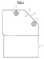
- Figures 1 and 2 illustrate an assembly comprising a housing of connector 1 and a cover 2 for holding and protecting the wires not shown connected to the connector.
- the connector housing 1 is intended to receive one or more connector modules not shown, in particular modules of the "SIM" type as marketed by the AIR LB group.
- the connector housing 1 is shown (see also by example Figures 8, 9 and 11) in the form of a housing parallelepiped having two opposite openings, namely a rear opening 3 of rectangular shape and a front opening not visible on the drawings.
- the front opening gives access to the contacts of modules mounted in the housing, for the coupling of these contacts with the additional contacts of the modules contained in another box connector not shown.
- the rear opening 3 makes it possible to insert, into the modules contained in the housing 1, the ends of the conductors not shown intended to be connected to said modules, these conductors preferably each having, at its end, a contact tip and lock, as is well known.
- the housing 1 has two locking elements 4 provided in positions opposite in said rear opening 3, in the form of two grooves parallels internally arranged in two opposite walls delimiting said opening.
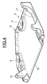
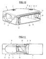
- the cover 2 comprises a body 5 shown in detail in the figure 3, and a cover 6 shown in detail in FIG. 4, the cover 6 being fixed to the body 5, for example using two screws 7 which appear on Figures 1 and 10. These screws 7 are screwed through through holes 8 of the cover 6 (figure 4) in threaded holes 9 of the cover body 5 (figure 3).
- the body 2 comprises, for the passage of the connected conductors to the connector arranged in the housing 1, two openings 10 and 11 are found here in two adjoining side walls at right angles one by compared to each other.
- the opening 11 is defined substantially half by the body 5 and cover 6, while the opening 10 on the connector side is mainly defined by the body 5.
- the body 5 of the cover comprises a fitting part 12 defining at minus one large side and the first small side of the rectangular opening 10, the cover 6 having a socket part 13 which defines the second large side of opening 10.
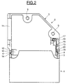
- the fitting part 12 comprises, at the place of said first small side delimiting the opening 10, a locking element 14 constituted by an external projection on said side in the form of a rib 14 whose shape and size are adapted to the shape and size one of the grooves 4 of the rear opening 3 of the connector housing 1.
- the element 15 consists of a metal blade 16, one of which end is folded into a U to form an anchoring part 17 and the other of which end is angled at 18, so as to constitute an external projection having a shape and a size adapted to said inner groove 4 of the rear opening 3 of the connector housing 1.
- the cover body 5 has for its part a housing 19 shaped so that the end anchor 17 of the blade 16 can be fitted there from the cover side and be held there in such a way that the blade 16 constitutes a tab in overhang elastically biased outwards, resting against a stop 20 which limits the bending of the blade 16 towards the outside, but allows on the other hand the blade to flex elastically inwards.
- the free end 18 of the blade 16 is angled at less than 90 ° so that, when the blade 16 is in contact against the stop 20, the end 18 makes an angle with the axis of the opening 10 less than 90 °, for example an angle between 45 and 60 °.
- the hood body 5 alone can be assembled provisionally with the housing 1, by engagement of its part 12 in the rear opening 3.
- blade 16 alone is not capable of ensuring a sufficiently reliable locking of the cover 2 on the housing 1. This is the reason for which locking means are provided on the cover of cover 6, to lock the blade 16 in the locking position of its free end 18 in the groove 4, according to FIG. 2, therefore pressing against the stop 20.
- These means of condemnation consist of a nose locking 21 projecting from the inner face of the cover 6, in such a way only when the cover 6 is placed on the cover body 5 (see FIGS. 8 and 9 and especially FIGS. 10 and 11), said nose 21 is placed opposite the inner face of the blade 16 whose free end 18 is snapped into the groove 4, so that after fixing the cover 6 on the body 5 using screws 7, the blade 16 is locked in the locked position by the nose 21.
- Unlocking the cover body 5, after removing the cover 6, can be done, without the use of any tool, by a simple traction exerted on the body 5 on the side of the elastic blade 16, traction under the effect of which, thanks to its bent end 18, the blade 16 flexes inward to allow its end 18 to come free of the groove 4.
- the elastic locking element 15 in bending instead of being constituted by a metal blade 16 attached to the body 5, could be constituted by a cantilever tab produced in one piece with the body 5.
- the use of the blade added metal 16 has the particular advantage of allowing a simpler embodiment of the cover body 5, insofar as it suffices to provide, on the latter, a housing (19) for the anchoring end 17 blade 16.
- cover 2 instead of being a cover with a 90 ° elbow (openings 10 and 11 in walls at right angles to each other the other), could of course also be a different cover, for example example straight or at any angle.
- the cover can be either a plug cover or a cover base, the cover body being able to be provided, as required, with fastening means, not shown because they are not part of the present invention.
- the cover provided with the following assembly means
- the invention can be a metal cover as well as a material cover plastic or composite material, if necessary metallized for the protection against electromagnetic radiation.
- the body and the hood cover can be either machined or molded. In both case, the metal blade 16 added simplifies the manufacture of the body hood.
- the locking nose 21 can preferably be made in one part with cover 6.
Landscapes
- Connector Housings Or Holding Contact Members (AREA)
- Coupling Device And Connection With Printed Circuit (AREA)
- Details Of Connecting Devices For Male And Female Coupling (AREA)
Abstract
Description
- la figure 1 est une vue de dessus d'un boítier de connecteur et d'un capot fixé à ce boítier;
- la figure 2 est une vue de dessus selon la figure 1, le couvercle du capot étant retiré et le boítier de connecteur étant représenté partiellement en coupe;
- la figure 3 est une vue en perspective du corps de capot;
- la figure 4 est une vue en perspective du couvercle de capot;
- la figure 5 est une vue analogue à celle de la figure 2, montrant une première phase d'assemblage du corps de capot avec le boítier de connecteur;
- la figure 6 est une vue en perspective du corps de capot et du boítier de connecteur, dans la même phase que la figure 5;
- la figure 7 est une vue analogue à celle de la figure 5, au cours d'une phase ultérieure d'assemblage;
- la figure 8 est une vue en perspective du boítier de connecteur et du capot, avant fermeture du couvercle de capot;
- la figure 9 est une vue latérale, partiellement en coupe, de l'ensemble suivant la figure 8;
- la figure 10 est une vue en perspective du capot, sans le boítier de connecteur, après fixation du couvercle sur le corps de capot; et
- la figure 11 est une vue latérale, partiellement en coupe, du capot suivant la figure 10, assemblé avec le boítier de connecteur.
Claims (8)
- Dispositif d'assemblage d'un boítier de connecteur et d'un capot de maintien et de protection des fils raccordés audit connecteur, ledit capot étant constitué d'un corps muni d'une partie d'emboítement s'ajustant dans une ouverture arrière du boítier de connecteur et d'un couvercle rapporté et fixé sur ledit corps en vue de la fermeture du capot, des moyens d'assemblage étant prévus sur ledit boítier et ledit capot pour le maintien du capot sur le boítier, caractérisé par le fait que lesdits moyens d'assemblage comprennent :deux premiers éléments de verrouillage (4) prévus dans des positions opposées au niveau de ladite ouverture arrière (3) du boítier (1);deux seconds éléments de verrouillage (14, 15) qui sont complémentaires desdits premiers éléments de verrouillage et sont prévus dans des positions opposées sur ladite partie d'emboítement (12), l'un au moins desdits seconds éléments de verrouillage étant élastiquement déformable de manière à pouvoir être amené, par déformation élastique, d'une position active de verrouillage à une position inactive de déverrouillage; etdes moyens de condamnation (21) prévus sur le couvercle (6) pour bloquer en position active ledit second élément de verrouillage déformable (15) lorsque le couvercle (6) est rapporté et fixé sur le corps de capot (5).
- Dispositif suivant la revendication 1, caractérisé par le fait que lesdits premiers moyens de verrouillage sont constitués par des creux (4) ménagés dans des faces opposées de ladite ouverture (3), et que lesdits seconds moyens de verrouillage comprennent des saillies (14, 18) dont l'une au moins est disposée sur une partie (16) élastiquement déformable.
- Dispositif suivant la revendication 2, caractérisé par le fait que ledit second élément de verrouillage (15) élastiquement déformable est constiué par une patte en porte-à-faux élastique en flexion.
- Dispositif suivant la revendication 3, caractérisé par le fait que ladite patte (15) est constituée par une patte rapportée sur le corps de capot (5).
- Dispositif suivant la revendication 4, caractérisé par le fait que le corps de capot (5) présente un logement (19) pour l'ancrage de ladite patte.
- Dispositif suivant la revendication 5, caractérisée par le fait que ladite patte (15) est constituée par une lame métallique (16) conformée par pliage.
- Dispositif suivant l'une quelconque des revendications précédentes, caractérisé par le fait que lesdits moyens de condamnation comprennent un élément (21) disposé en saillie sur la face intérieure du couvercle (6) de manière à bloquer ladite patte (15) en position active.
- Dispositif suivant la revendication 7, caractérisé par le fait que ledit élément est un nez (21) formé d'une seule pièce avec le couvercle (6).
Applications Claiming Priority (2)
| Application Number | Priority Date | Filing Date | Title |
|---|---|---|---|
| FR0001411 | 2000-02-04 | ||
| FR0001411A FR2804798B1 (fr) | 2000-02-04 | 2000-02-04 | Dispositif d'assemblage d'un boitier de connecteur et d'un capot de maintien et de protection des fils raccordes audit connecteur |
Publications (2)
| Publication Number | Publication Date |
|---|---|
| EP1122833A1 true EP1122833A1 (fr) | 2001-08-08 |
| EP1122833B1 EP1122833B1 (fr) | 2007-11-28 |
Family
ID=8846657
Family Applications (1)
| Application Number | Title | Priority Date | Filing Date |
|---|---|---|---|
| EP01400259A Expired - Lifetime EP1122833B1 (fr) | 2000-02-04 | 2001-02-02 | Dispositif d'assemblage d'un boîtier de connecteur et d'un capot de maintien et de protection des fils raccordés audit connecteur |
Country Status (5)
| Country | Link |
|---|---|
| EP (1) | EP1122833B1 (fr) |
| AT (1) | ATE379856T1 (fr) |
| DE (1) | DE60131582T2 (fr) |
| ES (1) | ES2292546T3 (fr) |
| FR (1) | FR2804798B1 (fr) |
Cited By (1)
| Publication number | Priority date | Publication date | Assignee | Title |
|---|---|---|---|---|
| EP1732175A3 (fr) * | 2005-06-08 | 2007-02-28 | Lapp Engineering & Co | Boîtier de connecteur angulaire avec couvercle |
Citations (4)
| Publication number | Priority date | Publication date | Assignee | Title |
|---|---|---|---|---|
| US5662491A (en) * | 1995-12-07 | 1997-09-02 | Chrysler Corporation | Electrical connector for vehicle power component switches |
| WO1997044862A1 (fr) * | 1996-05-23 | 1997-11-27 | The Siemon Company | Sortie modulaire a diaphonie reduite |
| EP0921600A2 (fr) * | 1997-12-04 | 1999-06-09 | Bradford K. Gauker | Ensemble connecteur d'amorce exempt d'orientation pour ensembles airbag d'automobiles |
| EP0967687A2 (fr) * | 1998-06-22 | 1999-12-29 | Itt Manufacturing Enterprises, Inc. | Rétention d'un insert dans un connecteur |
-
2000
- 2000-02-04 FR FR0001411A patent/FR2804798B1/fr not_active Expired - Fee Related
-
2001
- 2001-02-02 EP EP01400259A patent/EP1122833B1/fr not_active Expired - Lifetime
- 2001-02-02 AT AT01400259T patent/ATE379856T1/de not_active IP Right Cessation
- 2001-02-02 ES ES01400259T patent/ES2292546T3/es not_active Expired - Lifetime
- 2001-02-02 DE DE60131582T patent/DE60131582T2/de not_active Expired - Lifetime
Patent Citations (4)
| Publication number | Priority date | Publication date | Assignee | Title |
|---|---|---|---|---|
| US5662491A (en) * | 1995-12-07 | 1997-09-02 | Chrysler Corporation | Electrical connector for vehicle power component switches |
| WO1997044862A1 (fr) * | 1996-05-23 | 1997-11-27 | The Siemon Company | Sortie modulaire a diaphonie reduite |
| EP0921600A2 (fr) * | 1997-12-04 | 1999-06-09 | Bradford K. Gauker | Ensemble connecteur d'amorce exempt d'orientation pour ensembles airbag d'automobiles |
| EP0967687A2 (fr) * | 1998-06-22 | 1999-12-29 | Itt Manufacturing Enterprises, Inc. | Rétention d'un insert dans un connecteur |
Cited By (1)
| Publication number | Priority date | Publication date | Assignee | Title |
|---|---|---|---|---|
| EP1732175A3 (fr) * | 2005-06-08 | 2007-02-28 | Lapp Engineering & Co | Boîtier de connecteur angulaire avec couvercle |
Also Published As
| Publication number | Publication date |
|---|---|
| EP1122833B1 (fr) | 2007-11-28 |
| ATE379856T1 (de) | 2007-12-15 |
| FR2804798B1 (fr) | 2002-04-05 |
| DE60131582T2 (de) | 2008-10-23 |
| DE60131582D1 (de) | 2008-01-10 |
| FR2804798A1 (fr) | 2001-08-10 |
| ES2292546T3 (es) | 2008-03-16 |
Similar Documents
| Publication | Publication Date | Title |
|---|---|---|
| EP3231042B1 (fr) | Dispositif de prise électrique comprenant au moins un élément de verrouillage et déverrouillage | |
| EP1604085A1 (fr) | Boitier de cle | |
| FR2490027A1 (fr) | Connecteur a faible force d'insertion, destine par exemple a connecter un circuit integre a une plaquette de circuit imprime | |
| FR2684242A1 (fr) | Assemblage de connecteur electrique comportant un element de verrouillage des bornes. | |
| FR2749711A1 (fr) | Detrompage de connecteurs electriques | |
| WO2013182819A1 (fr) | Plaque de finition equipee de moyens de centrage sur un element interne d'un appareillage electrique | |
| FR2545285A1 (fr) | Connecteur electrique a verrouillage perfectionne | |
| FR2759205A1 (fr) | Dispositif de connexion electrique a securite de contact amelioree | |
| EP0581638B1 (fr) | Connecteur électrique | |
| EP1122833B1 (fr) | Dispositif d'assemblage d'un boîtier de connecteur et d'un capot de maintien et de protection des fils raccordés audit connecteur | |
| FR2503466A1 (fr) | Structure de connecteur a plusieurs contacts pour le branchement de remorques ou vehicules similaires | |
| EP1286427B1 (fr) | Bloc de jonction avec un bras de verrouillage pour connecteur enfichable | |
| EP0660447A1 (fr) | Perfectionnements aux éléments de boîtiers de connecteurs électriques | |
| EP2824785B1 (fr) | Ensemble articulé d un boîtier pour appareillage électrique et boîte de sol comprenant un tel ensemble | |
| EP0869580B1 (fr) | Connecteur à verrou secondaire intégré | |
| EP0744088A1 (fr) | Fiche electrique du type fiche anglaise | |
| EP3255732B1 (fr) | Borne de connexion electrique comportant un levier de connexion et appareillage electrique associe | |
| FR2805672A1 (fr) | Embout pour goulotte de cheminement de cables ou de conducteurs electriques | |
| FR2684244A1 (fr) | Connecteur codable. | |
| EP0954063A2 (fr) | Dispositif de connexion électrique à verrouillage | |
| FR2655207A1 (fr) | Connecteur electrique comportant des moyens perfectionnes de retenue de bornes. | |
| EP1241764B1 (fr) | Ensemble comportant un socle et un mécanisme, entrant dans la composition d'un appareil électrique, et présentant des moyens d'encliquetage perfectionnés du mécanisme sur le socle | |
| FR2751832A1 (fr) | Commande de meuble electromotorisee | |
| FR2866083A1 (fr) | Dispositif de fixation par encliquetage de deux elements et boitier le comportant | |
| EP3297099A1 (fr) | Verrou destiné au verrouillage d'une prise d'un reseau électrique et/ou de télécommunication |
Legal Events
| Date | Code | Title | Description |
|---|---|---|---|
| PUAI | Public reference made under article 153(3) epc to a published international application that has entered the european phase |
Free format text: ORIGINAL CODE: 0009012 |
|
| AK | Designated contracting states |
Kind code of ref document: A1 Designated state(s): AT BE CH CY DE DK ES FI FR GB GR IE IT LI LU MC NL PT SE TR |
|
| AX | Request for extension of the european patent |
Free format text: AL;LT;LV;MK;RO;SI |
|
| 17P | Request for examination filed |
Effective date: 20020124 |
|
| AKX | Designation fees paid |
Free format text: AT BE CH CY DE DK ES FI FR GB GR IE IT LI LU MC NL PT SE TR |
|
| RAP1 | Party data changed (applicant data changed or rights of an application transferred) |
Owner name: AMPHENOL-AIR LB |
|
| GRAP | Despatch of communication of intention to grant a patent |
Free format text: ORIGINAL CODE: EPIDOSNIGR1 |
|
| GRAS | Grant fee paid |
Free format text: ORIGINAL CODE: EPIDOSNIGR3 |
|
| GRAA | (expected) grant |
Free format text: ORIGINAL CODE: 0009210 |
|
| AK | Designated contracting states |
Kind code of ref document: B1 Designated state(s): AT BE CH CY DE DK ES FI FR GB GR IE IT LI LU MC NL PT SE TR |
|
| REG | Reference to a national code |
Ref country code: GB Ref legal event code: FG4D Free format text: NOT ENGLISH |
|
| GBT | Gb: translation of ep patent filed (gb section 77(6)(a)/1977) |
Effective date: 20071128 |
|
| REG | Reference to a national code |
Ref country code: IE Ref legal event code: FG4D Free format text: LANGUAGE OF EP DOCUMENT: FRENCH |
|
| REG | Reference to a national code |
Ref country code: CH Ref legal event code: EP |
|
| REF | Corresponds to: |
Ref document number: 60131582 Country of ref document: DE Date of ref document: 20080110 Kind code of ref document: P |
|
| REG | Reference to a national code |
Ref country code: ES Ref legal event code: FG2A Ref document number: 2292546 Country of ref document: ES Kind code of ref document: T3 |
|
| PG25 | Lapsed in a contracting state [announced via postgrant information from national office to epo] |
Ref country code: SE Free format text: LAPSE BECAUSE OF FAILURE TO SUBMIT A TRANSLATION OF THE DESCRIPTION OR TO PAY THE FEE WITHIN THE PRESCRIBED TIME-LIMIT Effective date: 20080228 Ref country code: NL Free format text: LAPSE BECAUSE OF FAILURE TO SUBMIT A TRANSLATION OF THE DESCRIPTION OR TO PAY THE FEE WITHIN THE PRESCRIBED TIME-LIMIT Effective date: 20071128 |
|
| NLV1 | Nl: lapsed or annulled due to failure to fulfill the requirements of art. 29p and 29m of the patents act | ||
| PG25 | Lapsed in a contracting state [announced via postgrant information from national office to epo] |
Ref country code: FI Free format text: LAPSE BECAUSE OF FAILURE TO SUBMIT A TRANSLATION OF THE DESCRIPTION OR TO PAY THE FEE WITHIN THE PRESCRIBED TIME-LIMIT Effective date: 20071128 |
|
| PG25 | Lapsed in a contracting state [announced via postgrant information from national office to epo] |
Ref country code: AT Free format text: LAPSE BECAUSE OF FAILURE TO SUBMIT A TRANSLATION OF THE DESCRIPTION OR TO PAY THE FEE WITHIN THE PRESCRIBED TIME-LIMIT Effective date: 20071128 |
|
| PG25 | Lapsed in a contracting state [announced via postgrant information from national office to epo] |
Ref country code: DK Free format text: LAPSE BECAUSE OF FAILURE TO SUBMIT A TRANSLATION OF THE DESCRIPTION OR TO PAY THE FEE WITHIN THE PRESCRIBED TIME-LIMIT Effective date: 20071128 |
|
| BERE | Be: lapsed |
Owner name: AMPHENOL-AIR LB Effective date: 20080228 |
|
| PG25 | Lapsed in a contracting state [announced via postgrant information from national office to epo] |
Ref country code: PT Free format text: LAPSE BECAUSE OF FAILURE TO SUBMIT A TRANSLATION OF THE DESCRIPTION OR TO PAY THE FEE WITHIN THE PRESCRIBED TIME-LIMIT Effective date: 20080428 |
|
| REG | Reference to a national code |
Ref country code: CH Ref legal event code: PL |
|
| REG | Reference to a national code |
Ref country code: IE Ref legal event code: FD4D |
|
| PLBE | No opposition filed within time limit |
Free format text: ORIGINAL CODE: 0009261 |
|
| STAA | Information on the status of an ep patent application or granted ep patent |
Free format text: STATUS: NO OPPOSITION FILED WITHIN TIME LIMIT |
|
| PG25 | Lapsed in a contracting state [announced via postgrant information from national office to epo] |
Ref country code: MC Free format text: LAPSE BECAUSE OF NON-PAYMENT OF DUE FEES Effective date: 20080228 Ref country code: LI Free format text: LAPSE BECAUSE OF NON-PAYMENT OF DUE FEES Effective date: 20080229 Ref country code: CH Free format text: LAPSE BECAUSE OF NON-PAYMENT OF DUE FEES Effective date: 20080229 Ref country code: IE Free format text: LAPSE BECAUSE OF FAILURE TO SUBMIT A TRANSLATION OF THE DESCRIPTION OR TO PAY THE FEE WITHIN THE PRESCRIBED TIME-LIMIT Effective date: 20071128 |
|
| 26N | No opposition filed |
Effective date: 20080829 |
|
| PG25 | Lapsed in a contracting state [announced via postgrant information from national office to epo] |
Ref country code: GR Free format text: LAPSE BECAUSE OF FAILURE TO SUBMIT A TRANSLATION OF THE DESCRIPTION OR TO PAY THE FEE WITHIN THE PRESCRIBED TIME-LIMIT Effective date: 20080229 |
|
| PG25 | Lapsed in a contracting state [announced via postgrant information from national office to epo] |
Ref country code: BE Free format text: LAPSE BECAUSE OF NON-PAYMENT OF DUE FEES Effective date: 20080228 |
|
| REG | Reference to a national code |
Ref country code: ES Ref legal event code: FD2A Effective date: 20080204 |
|
| PG25 | Lapsed in a contracting state [announced via postgrant information from national office to epo] |
Ref country code: CY Free format text: LAPSE BECAUSE OF FAILURE TO SUBMIT A TRANSLATION OF THE DESCRIPTION OR TO PAY THE FEE WITHIN THE PRESCRIBED TIME-LIMIT Effective date: 20071128 Ref country code: ES Free format text: LAPSE BECAUSE OF NON-PAYMENT OF DUE FEES Effective date: 20080204 |
|
| PG25 | Lapsed in a contracting state [announced via postgrant information from national office to epo] |
Ref country code: LU Free format text: LAPSE BECAUSE OF NON-PAYMENT OF DUE FEES Effective date: 20080202 |
|
| PG25 | Lapsed in a contracting state [announced via postgrant information from national office to epo] |
Ref country code: TR Free format text: LAPSE BECAUSE OF FAILURE TO SUBMIT A TRANSLATION OF THE DESCRIPTION OR TO PAY THE FEE WITHIN THE PRESCRIBED TIME-LIMIT Effective date: 20071128 |
|
| PG25 | Lapsed in a contracting state [announced via postgrant information from national office to epo] |
Ref country code: IT Free format text: LAPSE BECAUSE OF NON-PAYMENT OF DUE FEES Effective date: 20080229 |
|
| REG | Reference to a national code |
Ref country code: FR Ref legal event code: PLFP Year of fee payment: 16 |
|
| REG | Reference to a national code |
Ref country code: FR Ref legal event code: PLFP Year of fee payment: 17 |
|
| REG | Reference to a national code |
Ref country code: FR Ref legal event code: PLFP Year of fee payment: 18 |
|
| PGFP | Annual fee paid to national office [announced via postgrant information from national office to epo] |
Ref country code: FR Payment date: 20191218 Year of fee payment: 20 |
|
| PGFP | Annual fee paid to national office [announced via postgrant information from national office to epo] |
Ref country code: DE Payment date: 20200211 Year of fee payment: 20 Ref country code: GB Payment date: 20200219 Year of fee payment: 20 |
|
| REG | Reference to a national code |
Ref country code: DE Ref legal event code: R071 Ref document number: 60131582 Country of ref document: DE |
|
| REG | Reference to a national code |
Ref country code: GB Ref legal event code: PE20 Expiry date: 20210201 |
|
| PG25 | Lapsed in a contracting state [announced via postgrant information from national office to epo] |
Ref country code: GB Free format text: LAPSE BECAUSE OF EXPIRATION OF PROTECTION Effective date: 20210201 |