EP0968381B1 - Mecanisme desmodromique - Google Patents
Mecanisme desmodromique Download PDFInfo
- Publication number
- EP0968381B1 EP0968381B1 EP98904341A EP98904341A EP0968381B1 EP 0968381 B1 EP0968381 B1 EP 0968381B1 EP 98904341 A EP98904341 A EP 98904341A EP 98904341 A EP98904341 A EP 98904341A EP 0968381 B1 EP0968381 B1 EP 0968381B1
- Authority
- EP
- European Patent Office
- Prior art keywords
- cam
- primary
- transmitting members
- intermediate element
- cams
- Prior art date
- Legal status (The legal status is an assumption and is not a legal conclusion. Google has not performed a legal analysis and makes no representation as to the accuracy of the status listed.)
- Expired - Lifetime
Links
- 230000007246 mechanism Effects 0.000 title claims abstract description 98
- 230000033001 locomotion Effects 0.000 claims abstract description 21
- 239000012530 fluid Substances 0.000 claims 2
- 210000000056 organ Anatomy 0.000 description 21
- 238000006073 displacement reaction Methods 0.000 description 12
- 230000002093 peripheral effect Effects 0.000 description 7
- 238000005096 rolling process Methods 0.000 description 7
- 238000002485 combustion reaction Methods 0.000 description 6
- 239000003638 chemical reducing agent Substances 0.000 description 4
- 230000006835 compression Effects 0.000 description 4
- 238000007906 compression Methods 0.000 description 4
- 238000004880 explosion Methods 0.000 description 4
- 230000007423 decrease Effects 0.000 description 3
- 230000005540 biological transmission Effects 0.000 description 2
- 238000009826 distribution Methods 0.000 description 2
- 238000005461 lubrication Methods 0.000 description 2
- 238000004519 manufacturing process Methods 0.000 description 2
- 239000000203 mixture Substances 0.000 description 2
- 230000001154 acute effect Effects 0.000 description 1
- 239000000919 ceramic Substances 0.000 description 1
- 238000010276 construction Methods 0.000 description 1
- 238000010586 diagram Methods 0.000 description 1
- 230000005226 mechanical processes and functions Effects 0.000 description 1
- 229920003023 plastic Polymers 0.000 description 1
- 239000004033 plastic Substances 0.000 description 1
- 230000002441 reversible effect Effects 0.000 description 1
- 238000007789 sealing Methods 0.000 description 1
- 230000003068 static effect Effects 0.000 description 1
Images




Classifications
-
- F—MECHANICAL ENGINEERING; LIGHTING; HEATING; WEAPONS; BLASTING
- F01—MACHINES OR ENGINES IN GENERAL; ENGINE PLANTS IN GENERAL; STEAM ENGINES
- F01C—ROTARY-PISTON OR OSCILLATING-PISTON MACHINES OR ENGINES
- F01C1/00—Rotary-piston machines or engines
- F01C1/30—Rotary-piston machines or engines having the characteristics covered by two or more groups F01C1/02, F01C1/08, F01C1/22, F01C1/24 or having the characteristics covered by one of these groups together with some other type of movement between co-operating members
- F01C1/34—Rotary-piston machines or engines having the characteristics covered by two or more groups F01C1/02, F01C1/08, F01C1/22, F01C1/24 or having the characteristics covered by one of these groups together with some other type of movement between co-operating members having the movement defined in group F01C1/08 or F01C1/22 and relative reciprocation between the co-operating members
- F01C1/344—Rotary-piston machines or engines having the characteristics covered by two or more groups F01C1/02, F01C1/08, F01C1/22, F01C1/24 or having the characteristics covered by one of these groups together with some other type of movement between co-operating members having the movement defined in group F01C1/08 or F01C1/22 and relative reciprocation between the co-operating members with vanes reciprocating with respect to the inner member
- F01C1/3448—Rotary-piston machines or engines having the characteristics covered by two or more groups F01C1/02, F01C1/08, F01C1/22, F01C1/24 or having the characteristics covered by one of these groups together with some other type of movement between co-operating members having the movement defined in group F01C1/08 or F01C1/22 and relative reciprocation between the co-operating members with vanes reciprocating with respect to the inner member with axially movable vanes
-
- F—MECHANICAL ENGINEERING; LIGHTING; HEATING; WEAPONS; BLASTING
- F01—MACHINES OR ENGINES IN GENERAL; ENGINE PLANTS IN GENERAL; STEAM ENGINES
- F01C—ROTARY-PISTON OR OSCILLATING-PISTON MACHINES OR ENGINES
- F01C1/00—Rotary-piston machines or engines
- F01C1/30—Rotary-piston machines or engines having the characteristics covered by two or more groups F01C1/02, F01C1/08, F01C1/22, F01C1/24 or having the characteristics covered by one of these groups together with some other type of movement between co-operating members
- F01C1/34—Rotary-piston machines or engines having the characteristics covered by two or more groups F01C1/02, F01C1/08, F01C1/22, F01C1/24 or having the characteristics covered by one of these groups together with some other type of movement between co-operating members having the movement defined in group F01C1/08 or F01C1/22 and relative reciprocation between the co-operating members
- F01C1/344—Rotary-piston machines or engines having the characteristics covered by two or more groups F01C1/02, F01C1/08, F01C1/22, F01C1/24 or having the characteristics covered by one of these groups together with some other type of movement between co-operating members having the movement defined in group F01C1/08 or F01C1/22 and relative reciprocation between the co-operating members with vanes reciprocating with respect to the inner member
- F01C1/3446—Rotary-piston machines or engines having the characteristics covered by two or more groups F01C1/02, F01C1/08, F01C1/22, F01C1/24 or having the characteristics covered by one of these groups together with some other type of movement between co-operating members having the movement defined in group F01C1/08 or F01C1/22 and relative reciprocation between the co-operating members with vanes reciprocating with respect to the inner member the inner and outer member being in contact along more than one line or surface
- F01C1/3447—Rotary-piston machines or engines having the characteristics covered by two or more groups F01C1/02, F01C1/08, F01C1/22, F01C1/24 or having the characteristics covered by one of these groups together with some other type of movement between co-operating members having the movement defined in group F01C1/08 or F01C1/22 and relative reciprocation between the co-operating members with vanes reciprocating with respect to the inner member the inner and outer member being in contact along more than one line or surface the vanes having the form of rollers, slippers or the like
-
- F—MECHANICAL ENGINEERING; LIGHTING; HEATING; WEAPONS; BLASTING
- F16—ENGINEERING ELEMENTS AND UNITS; GENERAL MEASURES FOR PRODUCING AND MAINTAINING EFFECTIVE FUNCTIONING OF MACHINES OR INSTALLATIONS; THERMAL INSULATION IN GENERAL
- F16H—GEARING
- F16H25/00—Gearings comprising primarily only cams, cam-followers and screw-and-nut mechanisms
- F16H25/02—Gearings comprising primarily only cams, cam-followers and screw-and-nut mechanisms the movements of two or more independently moving members being combined into a single movement
-
- F—MECHANICAL ENGINEERING; LIGHTING; HEATING; WEAPONS; BLASTING
- F16—ENGINEERING ELEMENTS AND UNITS; GENERAL MEASURES FOR PRODUCING AND MAINTAINING EFFECTIVE FUNCTIONING OF MACHINES OR INSTALLATIONS; THERMAL INSULATION IN GENERAL
- F16H—GEARING
- F16H25/00—Gearings comprising primarily only cams, cam-followers and screw-and-nut mechanisms
- F16H25/04—Gearings comprising primarily only cams, cam-followers and screw-and-nut mechanisms for conveying rotary motion
- F16H25/06—Gearings comprising primarily only cams, cam-followers and screw-and-nut mechanisms for conveying rotary motion with intermediate members guided along tracks on both rotary members
-
- F—MECHANICAL ENGINEERING; LIGHTING; HEATING; WEAPONS; BLASTING
- F16—ENGINEERING ELEMENTS AND UNITS; GENERAL MEASURES FOR PRODUCING AND MAINTAINING EFFECTIVE FUNCTIONING OF MACHINES OR INSTALLATIONS; THERMAL INSULATION IN GENERAL
- F16H—GEARING
- F16H25/00—Gearings comprising primarily only cams, cam-followers and screw-and-nut mechanisms
- F16H25/08—Gearings comprising primarily only cams, cam-followers and screw-and-nut mechanisms for interconverting rotary motion and reciprocating motion
-
- F—MECHANICAL ENGINEERING; LIGHTING; HEATING; WEAPONS; BLASTING
- F02—COMBUSTION ENGINES; HOT-GAS OR COMBUSTION-PRODUCT ENGINE PLANTS
- F02B—INTERNAL-COMBUSTION PISTON ENGINES; COMBUSTION ENGINES IN GENERAL
- F02B53/00—Internal-combustion aspects of rotary-piston or oscillating-piston engines
-
- F—MECHANICAL ENGINEERING; LIGHTING; HEATING; WEAPONS; BLASTING
- F16—ENGINEERING ELEMENTS AND UNITS; GENERAL MEASURES FOR PRODUCING AND MAINTAINING EFFECTIVE FUNCTIONING OF MACHINES OR INSTALLATIONS; THERMAL INSULATION IN GENERAL
- F16H—GEARING
- F16H49/00—Other gearings
- F16H49/001—Wave gearings, e.g. harmonic drive transmissions
-
- Y—GENERAL TAGGING OF NEW TECHNOLOGICAL DEVELOPMENTS; GENERAL TAGGING OF CROSS-SECTIONAL TECHNOLOGIES SPANNING OVER SEVERAL SECTIONS OF THE IPC; TECHNICAL SUBJECTS COVERED BY FORMER USPC CROSS-REFERENCE ART COLLECTIONS [XRACs] AND DIGESTS
- Y10—TECHNICAL SUBJECTS COVERED BY FORMER USPC
- Y10T—TECHNICAL SUBJECTS COVERED BY FORMER US CLASSIFICATION
- Y10T74/00—Machine element or mechanism
- Y10T74/15—Intermittent grip type mechanical movement
- Y10T74/1503—Rotary to intermittent unidirectional motion
- Y10T74/1508—Rotary crank or eccentric drive
-
- Y—GENERAL TAGGING OF NEW TECHNOLOGICAL DEVELOPMENTS; GENERAL TAGGING OF CROSS-SECTIONAL TECHNOLOGIES SPANNING OVER SEVERAL SECTIONS OF THE IPC; TECHNICAL SUBJECTS COVERED BY FORMER USPC CROSS-REFERENCE ART COLLECTIONS [XRACs] AND DIGESTS
- Y10—TECHNICAL SUBJECTS COVERED BY FORMER USPC
- Y10T—TECHNICAL SUBJECTS COVERED BY FORMER US CLASSIFICATION
- Y10T74/00—Machine element or mechanism
- Y10T74/15—Intermittent grip type mechanical movement
- Y10T74/1503—Rotary to intermittent unidirectional motion
- Y10T74/1508—Rotary crank or eccentric drive
- Y10T74/1518—Rotary cam drive
-
- Y—GENERAL TAGGING OF NEW TECHNOLOGICAL DEVELOPMENTS; GENERAL TAGGING OF CROSS-SECTIONAL TECHNOLOGIES SPANNING OVER SEVERAL SECTIONS OF THE IPC; TECHNICAL SUBJECTS COVERED BY FORMER USPC CROSS-REFERENCE ART COLLECTIONS [XRACs] AND DIGESTS
- Y10—TECHNICAL SUBJECTS COVERED BY FORMER USPC
- Y10T—TECHNICAL SUBJECTS COVERED BY FORMER US CLASSIFICATION
- Y10T74/00—Machine element or mechanism
- Y10T74/15—Intermittent grip type mechanical movement
- Y10T74/1503—Rotary to intermittent unidirectional motion
- Y10T74/1508—Rotary crank or eccentric drive
- Y10T74/1518—Rotary cam drive
- Y10T74/1523—Radial cam
-
- Y—GENERAL TAGGING OF NEW TECHNOLOGICAL DEVELOPMENTS; GENERAL TAGGING OF CROSS-SECTIONAL TECHNOLOGIES SPANNING OVER SEVERAL SECTIONS OF THE IPC; TECHNICAL SUBJECTS COVERED BY FORMER USPC CROSS-REFERENCE ART COLLECTIONS [XRACs] AND DIGESTS
- Y10—TECHNICAL SUBJECTS COVERED BY FORMER USPC
- Y10T—TECHNICAL SUBJECTS COVERED BY FORMER US CLASSIFICATION
- Y10T74/00—Machine element or mechanism
- Y10T74/18—Mechanical movements
- Y10T74/18568—Reciprocating or oscillating to or from alternating rotary
Definitions
- the present invention relates to a desmodromic mechanism comprising a primary element and a secondary element mechanically connected by a desmodromic link, that is to say such that the speed of one of said elements leads to a well-determined speed for the other.
- variable speed drives Such mechanisms are found in variable speed drives, speed multipliers or reducers, hydraulic motors, pneumatic or combustion, compressors, pumps, cylinders, linear actuators, etc.
- gears which in some cases have major drawbacks, such as problems lubrication, noise, size, difficulties in obtaining displacements without game, cost price, etc.
- Patent DE 338495 discloses a mechanism as defined in the preamble of claim 1, this mechanism comprising a cam primary and a secondary cam as well as an intermediate element harboring bodies which slide or roll in their housing in allowing rotary movement between said three main parts.
- the housings of the bodies in the intermediate element constitute guides for their movement. These bodies have smooth surfaces ensuring permanent contact with the primary cam and the secondary cam and allow the drive between the two cams and the intermediate element.
- the cams are arranged so that the driven element rotates with a predetermined speed and different from the element speed engine.
- GB patent 1199257 describes a variable speed drive comprising also a primary cam, a secondary cam and an element intermediate who can perform relative rotary movements in modifying the speed of one or more driven elements compared to the speed of the driving element.
- This mechanism includes elements being in contact permanent with two cams and rolling in element housing intermediate serving as movement guides. The assembly and component design are different from the mechanism previous.
- Document US 3468175 discloses a mechanism for transmitting movement.
- this mechanism serves to transmission of rotary movements with a change in speed rotation and also has two cams and one element intermediate.
- This element hosts rolling bodies in their housing which are not in permanent contact with the two cams in this case.
- none of the above mechanisms includes a chamber watertight formed between the main elements of the mechanism which would allow such a mechanism to be used for example as a combustion, hydraulic motor, pneumatic motor, compressor or pump.
- Conventional mechanisms are therefore only suitable for their primary mechanical function as a motion transmitter or variable speed drive thus limiting their application and constituting a significant drawback.
- the goal is to realize the mechanisms mentioned above by a simple, precise, robust desmodromic system with a cost price lower than that of conventional designs.
- This system allows the use of plastics, ceramics in optimum conditions. It is possible to realize mechanisms that can operate without lubrication and with high mechanical resistance.
- the object of the present invention is to provide such a mechanism inexpensive, robust, easy-to-use, no-hassle gear and which makes it possible to cause a rotary movement of the element driven from a rotary movement of the motor element or vice versa, and which has a sealed chamber to allow the use of the mechanism e.g. as combustion engine, hydraulic motor, motor pneumatic, compressor or pump.
- the mechanism e.g. as combustion engine, hydraulic motor, motor pneumatic, compressor or pump.
- the subject of the present invention is a desmodromic mechanism tending to overcome the aforementioned drawbacks and to achieve the stated goals.
- This desmodromic mechanism is characterized by the combination of elements set out in claim 1.
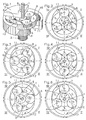
- Figure 1 is a partially exploded perspective view of a first embodiment of the mechanism.
- Figures 2 to 6 illustrate the successive positions of the mechanism for successive 90 ° rotations of the primary element of the mechanism.
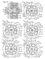
- Figures 7 and 8 illustrate an axial section and a longitudinal section of the mechanism in an application thereof for an internal combustion engine.
- Figures 9 to 12 illustrate the positions of the elements of the mechanism for the four-stroke engine intake, compression, explosion and exhaust.
- Figure 13 illustrates an axial section of the mechanism used as compressor.
- Figures 14 to 18 illustrate successive positions of the mechanism of the Figure 13 illustrating the operation of it as an air compressor.
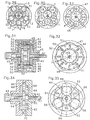
- Figures 19 to 23 illustrate the successive positions of a second form execution of the mechanism for angular increments of 90 ° of the element primary; the secondary element being stationary.
- Figures 24 to 28 illustrate the successive positions of the second form execution of the mechanism for increments of 30 ° of the secondary element, the intermediate element being stationary.
- Figures 29 and 30 illustrate two variants of a third form of the mechanism comprising five transmitting members.
- Figures 31 and 32 illustrate a fourth embodiment of the mechanism in which friction is removed by the use of elements turns.
- Figure 33 illustrates in plan and schematically a variant of the shape of the mechanism illustrated in FIGS. 31 and 32.
- Figures 34 and 35 illustrate a fifth embodiment of the mechanism.
- Figure 36 is an axial section of a sixth embodiment of the mechanism.
- Figures 37 to 41 illustrate the positions of the elements of the Figure 36 for successive increments of 90 ° of the primary element when the secondary element remains stationary.
- Figure 42 is a longitudinal sectional view of a seventh form execution of the mechanism.
- Figures 43 to 47 illustrate the successive positions of the mechanism of the FIG. 42 for angular displacements of 90 ° of the secondary element, the intermediate element being stationary.
- Figures 48, 49 and 50 are diagrams of the first embodiment of the mechanism illustrated in Figures 1 to 6 highlighting a characteristic fundamental peculiarity of the mechanism found in all its forms executions.
- the first embodiment of the desmodromic mechanism according to the invention illustrated in Figures 1 to 6 comprises an input shaft 1 whose end is provided with a primary cam 2 formed here by an eccentric to a lift.
- This mechanism also includes an output shaft 3, concentric with the shaft inlet 1, the end of which is provided with a plate 4 comprising bosses axial 5 defining between them rectilinear grooves or guides 6. This set constitutes an intermediate element of the mechanism.
- the primary cam 2 is located in the middle of the bosses 5 of the intermediate element.
- a casing 7 has bearings 8, 9 for the input 1 and output shafts 3 and has an internal cavity 10 in which the plate 4 and the primary cam 2.
- the peripheral wall of this internal cavity 10 of the casing 7 constitutes a secondary cam comprising in this embodiment two lifts 11, 12.
- Motion transmitters 13 are in the form cylindrical rollers and are arranged in each of the guides 6 located between the bosses 5 of the plate 4 of the intermediate element 3. These transmitting members 13 slide without play in the guides 6 between the bosses 5 and are in contact by their periphery simultaneously with the primary cam 2 and the secondary cam two tricks 11.12. In addition, these transmitting members 13 are supported permanent against at least one of the lateral faces of the guides 6 of the element intermediate. Thus, each transmitting member 13 is in permanent contact with the primary cam 2, the secondary cam and the intermediate element.
- a successive rotation of 90 ° (from Figure 3 to Figure 4) of the shaft input 1 causes, by lifting the primary cam, the displacement towards the exterior of the transmitting members 13b and 13c still in contact with the cam secondary again causing a 30 ° rotation of the intermediate element. From the position of figure 4 to that of figure 5 the force is transmitted from the cam primary 2 to the intermediate element by the transmitting members 13a and 13c. When the primary cam has made a new movement of 90 °, the element intermediate made a new rotation of 30 °. Then with a new 90 ° rotation of the primary cam 2 (from Figure 5 to Figure 6) these are the transmitters 13a and 13c which continue to drive the element intermediate of a new displacement of 30 °. At this moment, we return to the starting configuration of FIG.
- the transmitter member 13c having taken the position of the transmitting member 13a.
- the input shaft 1 and the primary cam 2 have rotated 360 ° and in doing so resulted in a desmodromic the intermediate element over an angular distance of 120 °, i.e. 1/3 of the distance angular distance traveled by the primary element 1.
- the mechanism described is strictly desmodromic, that is, the velocities of elements 1 and 3 are strictly proportional. If the speed of the input shaft 1 is constant, the speed of rotation of the input shaft output 3 will also be constant, without any ripple, at a value three times lower than that of input shaft 1.
- the transmitting member 13a is in contact with the top of the primary cam 2 and the hollow 11 of the cam secondary. In this position the tangents to the contact points of the organ transmitter 13a with the primary, respectively secondary, cams parallel to each other. In this position, the transmitting member 13a cannot transmit no torque or movement.
- the transmitting members are active, for a rotation of the primary cam 2 clockwise, when they are located in quadrants II and IV and passive when located in the quadrants I and III.
- the intermediate element it always finds at least one transmitting organ located in one of quadrants II and IV and at least one other in one of quadrants I and III, so there is always at minus a transmitting member active during the rotation of the mechanism.
- this provision makes it blocked in both directions whatever the angular position in which the intermediate member is stopped.
- the volume of the space 10 contained between two organs transmitters 13, the peripheral surface of the projection 5 of the intermediate element in contact with these transmitting members 13 and the portion of the surface internal device of the casing 7, or secondary cam is variable as a function of the rotation of the input shaft 1 and the primary cam 2. This feature allows to consider applications of this mechanism not only as a reducer or multiplier, but also as a motor, compressor or pump.
- variable volume 10 is then determined by two neighboring transmitters and the parts of the primary cam and secondary between these two transmitters.
- the number of transmitting members 13 is equal to number of lifts of primary cam 2 increased by the number of lifts 11.12 by the secondary cam, in this example equal to three.
- the center 0 of the three transmitting organs 13 is permanently located on a circle whose center coincides with the axis X of the primary cam 2.
- the primary cam 2 is constituted by an eccentric while the cam secondary consists of an oval surface.
- the primary cam 2 is located at inside the secondary cam.
- this mechanism is composed essentially a primary cam, a secondary cam and an element intermediate defining linear guides in which slides motion transmitting organs; the two cams and the intermediate element being movable relative to each other.
- cam primary may be inside the secondary cam or vice versa, or that the two cams can face each other axially; but still the element intermediate is between the two cams.
- the two cams can be mobile and the intermediate element stationary where one of the cams and the intermediate element are movable but then the other cam is stationary. Either of the cams can be driven the other cam or the intermediate element then being the coach or vice versa.
- Figures 7 and 8 illustrate in transverse and longitudinal section a application of the mechanism described above for the production of a explosion.
- the same reference numbers as in Figures 1 to 6 will be used to designate corresponding parts.
- the casing 7 is kept stationary and constitutes the engine block.
- it is made in three pieces in this example, two flanges 7a and 7b as well as a crown 7c. These three pieces 7a, 7b and 7c are integral with each other and stationary.
- the intermediate element comprises a shaft 3 journalled in the two flanges 7a, 7b of the casing.
- This shaft 3 is integral with two sides 20 connected between them by bridges 21 equivalent to bosses 5 of the first form execution of the mechanism.
- These flanks 20 rotate without play and tightly relative to the crown 7c, the median part of the internal face of which constitutes the secondary cam comprising the two lifts 11,12.
- the input shaft 1 is journalled in the shaft 3 and carries the primary cam 2.
- the transmitting members 13 are arranged between the bridges 21, the face internal or secondary cam of the casing 7c, the primary cam 2 and the flanks 20. These transmitting members 13 ensure tight contact between the parts with which they are in contact and thus delimit three variable volume chambers 10a, 10b, 10c.
- a needle bearing is provided in this embodiment 22 between an eccentric 23 integral with the shaft 1 and a circular ring constituting the external surface of the primary cam 2.
- the crown 7c of the housing also includes an intake manifold 24 of a combustible mixture, an exhaust pipe 25 of the combustion and a spark plug 26, angularly offset by about 120 ° one to another.
- the transmitting members 13 can be tubular and provided with means sealing guaranteeing good compression and a low coefficient of friction and rolling.
- Figure 9 illustrates the admission of the gas mixture into the chamber with variable volume 10c through the conduit 24.
- the primary cam 2 and the element intermediate rotate clockwise.
- Figure 10 illustrates the engine when compression is about to reach maximum in the variable volume chamber 10c and where the explosion is caused by the spark plug 26.
- figure 11 illustrates the engine in expansion phase of the variable volume chamber 10c
- FIG. 12 illustrates the exhaust 25 of the variable volume chamber 10c. It's obvious that the three variable volume chambers go through the same four-stroke cycle, so that for a complete revolution of the intermediate element 3.21 each variable volume chamber 10a, 10b, 10c will have an explosion time and expansion. In doing so, the shaft 1 and the primary cam 2 will have made three turns complete.
- Such an engine therefore has two rotary power take-offs, the shaft 1 integral with the primary cam and the intermediate element 3, the speed of rotation of this intermediate element 3 being three times weaker than that of the element primary 1.
- Figures 13 to 18 illustrate another embodiment of the mechanism and its application as a compressor.
- the mechanism comprises a casing formed by two flanges 130,131, of which one has a hub 132, connected by a crown 133 whose internal surface 134 constitutes the secondary cam which here has four lifts.
- the intermediate element is formed by two sides 135,136 connected by bridges 137, provided with air passages 137a, defining guides between them radial rectilinear lines in which transmitting members 138 formed by tubular elements.
- the connection between each rotary 135,136 flank and the fixed crown 133 is waterproof.
- the mechanism also includes a primary cam 139 at a raised lift by an eccentric secured to an input shaft 140 pivoted in the flange 130 and the hub 132 of the casing.
- the transmitting members 138 slide tightly between the sides 135.136 but not tight in the radial guides and are in permanent contact and sealed with the two primary 139 and secondary 134. cams. transmitters thus define with the primary and secondary cams watertight chambers with variable volume 150, five in number.
- This mechanism also includes at least one supply orifice 141 in the hub 132 of the casing communicating by a bore 142 of the flank 136 with a distribution sector 143 hollowed out in one of the lateral faces of the cam primary 139.
- This mechanism also includes an exhaust duct 144 in the hub 132 of the casing, communicating with a bore 145, made in the end of the shaft 140 and the primary cam 139, opening towards the periphery of this primary cam.
- Distribution sector 143 extends over an angular extent substantially equal to 90 ° and one of its ends is diametrically opposite to the axis of the hole 145.
- the casing is stationary, and for a complete 360 ° revolution of the input shaft 140 secured to the cam primary 139 the intermediate element rotates 72 ° or 1/5 of a turn.
- the volume chamber variable 150a is at its lowest volume, isolated from intake 143 and the exhaust 145.
- the variable volume chamber 150b is connected to the exhaust 145 while the variable volume chambers 150 d and e are related to admission.
- a rotation of the input shaft 140 and the primary cam 139 by 45 ° causes rotation of the intermediate element and the chambers variable volume 150 of 9 ° bringing the mechanism into the position illustrated in the figure 15.
- variable volume chamber 150 a is connected to the intake and the chamber variable volume 150 b is exhausted.
- the volume of the chamber 150a increases while the volume of the chamber 150b decreases driving the gas it contains in the exhaust duct 144.
- the chamber 150 b is at its smallest volume and it is not more connected to the exhaust but it is the chamber 150 c which is connected to the exhaust while the chambers 150 d and a are connected to the intake.
- the variable volume chamber 150 c decreases in volume and expels its contents on exhaust.
- the chamber variable volume 150 d expels its contents on exhaust while the chambers 150c and 150b fill up since they are connected to the intake.
- the mechanism thus constitutes a continuous compressor.
- the mechanism according to the invention can be used as mechanical reduction or multiplier ( Figures 1 to 6), as an internal combustion engine ( Figures 7 to 12) or as a compressor or hydraulic or pneumatic motor ( Figures 13 to 18). It is also applied to perform movements linear for example for cylinders, linear actuators displacements of elements of indefinite lengths replacing racks, chains, etc. So, using the same mechanical principle, several very diverse applications are possible which makes this mechanism particularly versatile.
- the embodiment of the desmodromic mechanism according to the invention illustrated in FIGS. 19 to 23 comprises an input shaft 1 secured to a cam primary 2 to a lift and a fixed casing 7 having a secondary cam to three lifts formed by the internal peripheral wall of this casing 7.
- the intermediate element here comprises an output shaft integral with a plate 4 having four bosses 5 uniformly distributed over its circumference and determining between them four guides 6 receiving the organs transmitters 13, sliding without play in these guides and bearing against the primary 2 and secondary cams and these bosses 5.
- the sum of the lifts of the primary cam 2 and the lifts of the cam secondary 7 is four, equal to the number of transmitting members 13.
- a 4: 1 gear ratio is achieved between the angular displacements of the input shaft 1 secured to the primary cam 2 and the intermediate element 3.5.
- the two shafts 1,3 rotate in the same direction.
- the input shaft 1 carries a eccentric 30 on which a primary tubular cam 31 is mounted idly using of a needle bearing 32.
- This primary cam 31 has a single lift.
- the intermediate element integral with the output shaft 3, comprises a plate 4 provided with five bosses 5 uniformly disposed around the axis of said plate 4 and defining five rectilinear radial guides 6 each receiving a transmitting member 13 sliding without play in these guides and the members transmitters 13 are tubular to reduce inertia and deform slightly during the rotation of the system and ensure a free play when stopped.
- the internal peripheral wall of the casing 7 has four lifts 33 which constitute the secondary cam.
- the number of transmitting members 13 is equal to the sum of the levies of the primary cam 31 and lifts 33 of the secondary cam, ie five. If the housing 7 is kept stationary, one obtains for each complete revolution of the primary cam 30.31 angular displacement in the same direction of the element intermediate 4.5 of 72 °, or 1/5 of a turn.
- the shape of the secondary cam is different although it also includes four levies 34.
- the rule of the sum of the values y, z is applied in these two variants.
- the distance between the low point of the primary cam 2 of each low point of the secondary cam is equal to diameter of a transmitting member, as well as the distance between the point top of the primary cam of each point top of the secondary cam when these points are aligned on a diameter of the mechanism.
- center of the transmitting members 13 is always located on a circle whose center coincides with the axis of the eccentric and therefore of the cam primary 30.
- Figures 31 and 32 illustrate an embodiment of the mechanism comprising an input shaft 41 secured to a central drum 42 bearing each of its axial ends a primary cam to a lift 43, these cams 43 being perfectly angularly aligned.
- This input shaft 41 is journalled on an intermediate element comprising two integral flanges 44 each of a pin 45, located on either side of the primary cams 43.
- These trunnions are pivoted mad in the casing formed by two lateral flanks 46 connected by a ring 47, the central section 48 of the inner face of which constitutes the secondary cam.
- the primary cam 43 is constituted by an eccentric comprising a lift and the secondary cam 48 by a casing having seven lifts uniformly distributed around the axis of the mechanism.
- This mechanism also includes eight transmitting members, each consisting of an axis 49 carrying a central roller 50 cooperating with the cam secondary 48 and two side rollers 51 each cooperating respectively with one of the primary cams 43.
- the axes 49 slide without play in slots 52 radial which comprise the flanges 44 of the intermediate element and serving as guides to the transmitting organs.
- the distances separating, taken on a radius of the mechanism, the high and low points respectively of the primary and secondary cams are equal the diameter of the transmitting members.
- Axes 49 of the transmitting organs are arranged on a circumference whose center coincides with the axis of the eccentric 43.
- FIG. 33 illustrates a variant of this embodiment in which one transmitter body 51 out of two has been eliminated.
- Secondary cam 48 always has seven lifts, the primary cam 42 has one, but the number of transmitting organs 52 is four. This does not change the ratio of division which is always equal to 1/8. This solution simplifies the manufacturing for uses where the cost price is important and the input torque low.
- the intermediate member is of the type of that illustrated in Figures 1 to 6 for example and has a plate 4 provided with bosses 5 constituting linear guides.
- the transmitting members 52 are made up by cylindrical rollers.
- the mechanism comprises an input shaft 61 comprising two opposite eccentrics 62 angularly and together forming a primary cam with two lifts.
- the intermediate element comprises an output shaft 63 carrying a plate 64 provided with three bosses 65 defining between them radial rectilinear guides for transmitters 66 juxtaposed two by two in each of these guides and each cooperating with one of the eccentrics 62.
- One of the ends of the input shaft 61 is journalled in the output shaft 63 while the other is in one half 67 of the housing 67.68.
- the housing 67.68 has on the internal face of each of its halves 67.68 a secondary cam 69.70 with two lifts each.
- the cams secondary 69.70 are offset by 90 ° so as to form a cam secondary to four tricks in total.
- the sum of the lifts of the primary cam 62 and the lifts of the cam secondary 69.70 is six, equal to the number of transmitting organs 66.
- the gear ratio is three.
- the input and output shafts rotate in the same direction.
- the number of transmitting organs is generally equal to the number of lifts of the secondary cam increased by one unit.
- the input shaft 1 carries a primary cam 2 with two lifts.
- the intermediate element or tree of outlet 3 comprises a plate 4 provided with bosses 5 defining eight guides 6 for eight transmitters 13.
- the casing 7 has a internal peripheral surface forming the secondary cam which has six lifts.
- the casing 7 being kept fixed, the output shaft 3 rotates four times slower than input tree 1, which corresponds to the number eight, divided by the number of primary cam lifts, two.
- the two shafts 1 and 3 rotate in the same meaning.
- the shaft 1 is provided a primary cam 2 with four lifts arranged symmetrically around this axis.
- the intermediate element consists of a housing 80 pivoted on the shaft input 1 on either side of the primary cam 2.
- This housing 80 has five holes 81 made in its peripheral wall, uniformly distributed around of the axis of this cage 80 and constituting housings or guides for transmitting members constituted by spherical balls 82.
- the secondary cam is here formed by a ring 83 pivoted on the housing 80 and whose inner surface 84 which is eccentric constitutes the secondary cam which here presents only one lifting.
- the organs transmitters are always in constant contact with the primary cams and secondary and with the intermediate element in which they slide radially.
- the shape of the transmitters may vary. However, they generally have a peripheral spherical or cylindrical portion of circular section which is in contact with each of the primary and secondary cams.
- the transmitting members slide radially and perpendicularly relative to to the axis of the mechanism.
- the transmitting organs may include a body cylindrical and rounded ends. These transmitting organs can also be formed from the juxtaposition of several rotating elements for limit friction.
- the guide axes of the rectilinear guides of the intermediate element are arranged radially and / or perpendicular to the axis of the mechanism.
- each transmitting member can be connected to the body of the intermediate element by a connecting rod articulated on the body of the element intermediate and carrying the transmitting organ.
- a connecting rod articulated on the body of the element intermediate and carrying the transmitting organ there is no friction but only a rolling of the transmitting members on the primary and secondary cams and on the body of the intermediate element.
- the displacement of the transmitting members relative to the body of the intermediate element is carried out in an arc of circle or according to a curvilinear and not straight path.
Landscapes
- Engineering & Computer Science (AREA)
- General Engineering & Computer Science (AREA)
- Mechanical Engineering (AREA)
- Transmission Devices (AREA)
- Saccharide Compounds (AREA)
- Branching, Merging, And Special Transfer Between Conveyors (AREA)
- Reciprocating Conveyors (AREA)
- Gears, Cams (AREA)
Description
Claims (8)
- Mécanisme desmodromique comportant :dans lequel les organes transmetteurs présentent des surfaces de contact avec les cames, de forme telle qu'elles assurent un contact permanent et simultané avec les cames primaire et secondaire; la came primaire, la came secondaire et l'élément intermédiaire étant assemblés les uns aux autres de façon à se déplacer rotativement et/ou linéairement les uns par rapport aux autres d'une façon impérative et avec des vitesses différentielles invariables pour toutes les positions du mécanisme; l'élément intermédiaire étant constitué d'un corps (3, 4, 5) comportant des guides (6) dans chacun desquels coulisse librement un organe transmetteur (13); ce mécanisme étant caractérisé par le fait que l'espace compris entre deux organes transmetteurs adjacents, la portion du corps de l'élément intermédiaire comprise entre ces deux organes transmetteurs, la portion de came secondaire également comprise entre ces deux organes transmetteurs et les deux faces d'appui des extrémités axiales des organes transmetteurs constitue une chambre étanche à volume variable (10) en fonction de la position relative des cames primaire et secondaire et de l'élément intermédiaire.a) des organes transmetteurs (13) de mouvement reliés à un élément intermédiaire et prenant appui sur celui-ci;b) une came primaire (2) en contact permanent avec chacun des organes transmetteurs (13);c) une came secondaire en contact permanent avec chacun des organes transmetteurs (13);
- Mécanisme selon la revendication 1, caractérisé par le fait que l'élément intermédiaire (3, 4, 5, 6) comporte des passages entre deux organes transmetteurs (13) adjacents et que l'espace compris entre deux organes transmetteurs adjacents et les cames primaire et secondaire d'une part, et d'autre part entre les faces frontales des organes transmetteurs (13) et leurs faces d'appui, constitue la chambre à volume variable (10).
- Mécanisme selon la revendication 2, caractérisé par le fait que la came primaire (139), par des lumières judicieusement placées sur son pourtour, a une fonction de distributeur de fluide.
- Mécanisme selon les revendications 2 et 3, caractérisé par le fait qu'au moins un secteur (143) disposé sur le pourtour de la came primaire est en communication avec au moins une chambre à volume variable.
- Mécanisme selon les revendications 2 et 3, caractérisé par le fait qu'un perçage (145) débouche sur la périphérie de la came primaire (139).
- Mécanisme selon la revendication 1, caractérisé par le fait que la came secondaire, par des tubulures (24, 25) judicieusement placées sur son pourtour, a une fonction de distributeur de fluide.
- Mécanisme selon la revendication 1, caractérisé par le fait que les axes de guidage des guides rectilignes (6) de l'élément intermédiaire sont disposés radialement et/ou perpendiculairement à l'axe du mécanisme.
- Mécanisme selon la revendication 1, caractérisé par le fait que les organes transmetteurs (13) sont munis d'un bandage déformable élastiquement.
Priority Applications (1)
| Application Number | Priority Date | Filing Date | Title |
|---|---|---|---|
| EP02025169A EP1286084B1 (fr) | 1997-03-18 | 1998-03-10 | Mécanisme desmodromique |
Applications Claiming Priority (3)
| Application Number | Priority Date | Filing Date | Title |
|---|---|---|---|
| CH66297 | 1997-03-18 | ||
| CH00662/97A CH697259B1 (fr) | 1997-03-18 | 1997-03-18 | Mécanisme desmodromique à cames. |
| PCT/IB1998/000310 WO1998041781A1 (fr) | 1997-03-18 | 1998-03-10 | Mecanisme desmodromique |
Related Child Applications (1)
| Application Number | Title | Priority Date | Filing Date |
|---|---|---|---|
| EP02025169A Division EP1286084B1 (fr) | 1997-03-18 | 1998-03-10 | Mécanisme desmodromique |
Publications (2)
| Publication Number | Publication Date |
|---|---|
| EP0968381A1 EP0968381A1 (fr) | 2000-01-05 |
| EP0968381B1 true EP0968381B1 (fr) | 2003-01-22 |
Family
ID=4192218
Family Applications (2)
| Application Number | Title | Priority Date | Filing Date |
|---|---|---|---|
| EP02025169A Expired - Lifetime EP1286084B1 (fr) | 1997-03-18 | 1998-03-10 | Mécanisme desmodromique |
| EP98904341A Expired - Lifetime EP0968381B1 (fr) | 1997-03-18 | 1998-03-10 | Mecanisme desmodromique |
Family Applications Before (1)
| Application Number | Title | Priority Date | Filing Date |
|---|---|---|---|
| EP02025169A Expired - Lifetime EP1286084B1 (fr) | 1997-03-18 | 1998-03-10 | Mécanisme desmodromique |
Country Status (10)
| Country | Link |
|---|---|
| US (1) | US6231468B1 (fr) |
| EP (2) | EP1286084B1 (fr) |
| JP (1) | JP4278184B2 (fr) |
| AT (2) | ATE332459T1 (fr) |
| AU (1) | AU730221B2 (fr) |
| CA (1) | CA2284739C (fr) |
| CH (1) | CH697259B1 (fr) |
| DE (2) | DE69835171T2 (fr) |
| ES (1) | ES2266390T3 (fr) |
| WO (1) | WO1998041781A1 (fr) |
Families Citing this family (18)
| Publication number | Priority date | Publication date | Assignee | Title |
|---|---|---|---|---|
| JP4818727B2 (ja) * | 2002-10-16 | 2011-11-16 | シンキネティクス・インコーポレイテッド | 軸出力を制御するための多速度比装置 |
| US7134846B2 (en) * | 2004-05-28 | 2006-11-14 | Stanadyne Corporation | Radial piston pump with eccentrically driven rolling actuation ring |
| CA2541352A1 (fr) * | 2005-08-09 | 2007-02-09 | Martin Boudreau | Boites de vitesse multi-fonctions |
| US8113805B2 (en) | 2007-09-26 | 2012-02-14 | Torad Engineering, Llc | Rotary fluid-displacement assembly |
| KR101163889B1 (ko) * | 2010-06-18 | 2012-07-09 | 현대자동차주식회사 | 변속기의 유성기어장치 |
| RU2502003C2 (ru) * | 2010-07-21 | 2013-12-20 | Борис Васильевич Меркурьев | Механическая бесступенчатая передача, способ управления механической бесступенчатой передачей, синхронно-адаптивная схема |
| WO2012162802A1 (fr) * | 2011-06-01 | 2012-12-06 | Magna Seating Inc. | Articulation à disque, à réducteur à planétaire, pour siège de véhicule automobile |
| US9061760B2 (en) | 2012-08-02 | 2015-06-23 | Bell Helicopter Textron Inc. | Independent blade control system with rotary blade actuator |
| US9376205B2 (en) | 2012-08-02 | 2016-06-28 | Bell Helicopter Textron Inc. | Radial fluid device with variable phase and amplitude |
| US9162760B2 (en) * | 2012-08-02 | 2015-10-20 | Bell Helicopter Textron Inc. | Radial fluid device with multi-harmonic output |
| US10240666B2 (en) | 2013-03-12 | 2019-03-26 | Motus Labs, LLC | Simplified gearbox mechanism |
| US10626964B2 (en) | 2013-03-12 | 2020-04-21 | Motus Labs, LLC | Axial cam gearbox mechanism |
| US10428916B2 (en) * | 2013-03-12 | 2019-10-01 | Motus Labs, LLC | Spiral cam gearbox mechanism |
| US11015685B2 (en) | 2013-03-12 | 2021-05-25 | Motus Labs, LLC | Axial cam gearbox mechanism |
| US10151375B2 (en) | 2013-03-12 | 2018-12-11 | Motus Labs, LLC | Motorized gearbox mechanism |
| US10017994B2 (en) | 2014-10-17 | 2018-07-10 | Ashmin Holding Llc | Boring apparatus and method |
| WO2017048571A1 (fr) | 2015-09-14 | 2017-03-23 | Torad Engineering Llc | Dispositif d'hélice à aubes multiples |
| CN109695695A (zh) * | 2018-12-17 | 2019-04-30 | 广州市昊志机电股份有限公司 | 一种内置谐波减速器的气动转台 |
Family Cites Families (30)
| Publication number | Priority date | Publication date | Assignee | Title |
|---|---|---|---|---|
| DE350767C (de) * | 1922-03-24 | Wilhelm Vogt | UEbersetzungsgetriebe | |
| US1470560A (en) * | 1923-10-09 | Variable speed mechanism | ||
| US1194288A (en) * | 1916-08-08 | Mechanical movement | ||
| DE338495C (de) * | 1919-12-03 | 1921-06-20 | Wilhelm Vogt | UEbersetzungsgetriebe |
| US1449352A (en) * | 1921-09-20 | 1923-03-20 | Ferdinand W Seeck | Gearless planetary transmission |
| US1706180A (en) * | 1926-06-23 | 1929-03-19 | Morison Inc | Epicyclic double-reduction transmission |
| US1738662A (en) * | 1927-01-20 | 1929-12-10 | Morison Inc | Ball transmission |
| CH151431A (fr) * | 1929-07-20 | 1931-12-15 | Scheuer Prosper | Dispositif réducteur de vitesse. |
| DE1083833B (de) * | 1959-03-20 | 1960-06-23 | Franz Doll | Kolbenmotor |
| US3403668A (en) * | 1966-04-04 | 1968-10-01 | Schottler Henry | Fluid transducer |
| GB1199257A (en) * | 1966-10-22 | 1970-07-22 | Patrick George Leeson | Speed Changing Mechanisms |
| US3468175A (en) | 1967-08-15 | 1969-09-23 | Jan W Rabek | Transmission |
| US3589202A (en) * | 1969-03-19 | 1971-06-29 | Richard B Stanley | Linear actuator |
| US3910733A (en) * | 1969-09-18 | 1975-10-07 | Leslie H Grove | Rotary mechanism having at least two camming elements |
| US3874253A (en) * | 1973-05-31 | 1975-04-01 | Clive Waddington | Waddington drive |
| GB1432023A (en) * | 1973-07-03 | 1976-04-14 | Variable Kinetic Drives Ltd | Load moving apparatus |
| US4109541A (en) * | 1974-04-29 | 1978-08-29 | Gerhard Jesse | Friction gear |
| US4566352A (en) * | 1978-12-01 | 1986-01-28 | Bernard Stiff | Rotary shaft control apparatus |
| US4338830A (en) * | 1979-11-02 | 1982-07-13 | Rodaway Keith S | Subtractive and additive differential gear reduction system |
| US4478100A (en) * | 1982-03-08 | 1984-10-23 | Sfredda Albert P | Automatic transmission |
| DE3364922D1 (en) * | 1982-05-28 | 1986-09-04 | Rhp Group Plc | Devices for converting rotary movement into linear movement |
| JPS60256643A (ja) * | 1984-05-31 | 1985-12-18 | Moritomo Ando | 減速装置 |
| US4856378A (en) * | 1985-06-10 | 1989-08-15 | Djh Engineering Center, Inc. | Variable speed transmission |
| JPS63130956A (ja) * | 1986-11-18 | 1988-06-03 | Bridgestone Cycle Co | 無段変速装置 |
| JPS63275834A (ja) * | 1987-04-30 | 1988-11-14 | Komatsu Ltd | 減速伝動装置 |
| DE3878023T2 (de) * | 1987-05-14 | 1993-06-09 | Sumitomo Heavy Industries | Planetengetriebesystem. |
| JP2966536B2 (ja) * | 1990-12-27 | 1999-10-25 | 加茂精工株式会社 | 転動ボール形差動減速装置 |
| JPH0533840A (ja) * | 1991-07-29 | 1993-02-09 | Canon Inc | 遊星摩擦式変速装置 |
| CA2108108A1 (fr) * | 1993-10-08 | 1995-04-09 | George F. Round | Moteur rotatif |
| US5431605A (en) * | 1993-11-30 | 1995-07-11 | Ko; Chung C. | Speed reducer which employs rolling means |
-
1997
- 1997-03-18 CH CH00662/97A patent/CH697259B1/fr not_active IP Right Cessation
-
1998
- 1998-03-10 CA CA002284739A patent/CA2284739C/fr not_active Expired - Fee Related
- 1998-03-10 JP JP54027198A patent/JP4278184B2/ja not_active Expired - Lifetime
- 1998-03-10 AT AT02025169T patent/ATE332459T1/de not_active IP Right Cessation
- 1998-03-10 ES ES02025169T patent/ES2266390T3/es not_active Expired - Lifetime
- 1998-03-10 US US09/381,092 patent/US6231468B1/en not_active Expired - Lifetime
- 1998-03-10 EP EP02025169A patent/EP1286084B1/fr not_active Expired - Lifetime
- 1998-03-10 DE DE69835171T patent/DE69835171T2/de not_active Expired - Lifetime
- 1998-03-10 WO PCT/IB1998/000310 patent/WO1998041781A1/fr not_active Ceased
- 1998-03-10 AU AU62271/98A patent/AU730221B2/en not_active Ceased
- 1998-03-10 AT AT98904341T patent/ATE231593T1/de not_active IP Right Cessation
- 1998-03-10 DE DE69810909T patent/DE69810909T2/de not_active Expired - Lifetime
- 1998-03-10 EP EP98904341A patent/EP0968381B1/fr not_active Expired - Lifetime
Also Published As
| Publication number | Publication date |
|---|---|
| ES2266390T3 (es) | 2007-03-01 |
| EP0968381A1 (fr) | 2000-01-05 |
| JP4278184B2 (ja) | 2009-06-10 |
| DE69835171D1 (de) | 2006-08-17 |
| CA2284739C (fr) | 2006-05-09 |
| ATE231593T1 (de) | 2003-02-15 |
| DE69810909D1 (de) | 2003-02-27 |
| AU730221B2 (en) | 2001-03-01 |
| DE69835171T2 (de) | 2007-06-28 |
| WO1998041781A1 (fr) | 1998-09-24 |
| CA2284739A1 (fr) | 1998-09-24 |
| EP1286084A3 (fr) | 2003-06-11 |
| DE69810909T2 (de) | 2003-11-06 |
| AU6227198A (en) | 1998-10-12 |
| EP1286084B1 (fr) | 2006-07-05 |
| CH697259B1 (fr) | 2008-07-31 |
| ATE332459T1 (de) | 2006-07-15 |
| JP2001515573A (ja) | 2001-09-18 |
| US6231468B1 (en) | 2001-05-15 |
| EP1286084A2 (fr) | 2003-02-26 |
Similar Documents
| Publication | Publication Date | Title |
|---|---|---|
| EP0968381A1 (fr) | Mecanisme desmodromique | |
| FR2501784A1 (fr) | Moteur a mouvement lineaire et plateau oscillant pour un tel moteur | |
| CA2182742C (fr) | Machine a pistons rotatifs utilisable notamment en tant que moteur thermique | |
| FR2833048A1 (fr) | Machine volumetrique rotative fonctionnant sans frottement dans le volume de travail et supportant des pressions et des temperatures elevees | |
| EP0627042B1 (fr) | Machine volumetrique a pistons louvoyants, en particulier moteur a quatre temps | |
| FR2510219A1 (fr) | Dispositif convertisseur de mouvement | |
| FR2518646A1 (fr) | Moteur a combustion a piston rotatif | |
| CH645698A5 (fr) | Machine a chambres et pistons oscillants. | |
| FR2652391A1 (fr) | Pompes et moteurs a multirotors. | |
| EP2356318A1 (fr) | Machine rotative a losange deformable comportant un mecanisme de transmission perfectionne | |
| FR2721684A1 (fr) | Pompe doseuse d'huile pour moteurs à deux temps. | |
| FR2809453A1 (fr) | Moteur rotatif a palettes fonctionnant selon les memes cycles que les moteurs dits alternatifs | |
| FR2898383A1 (fr) | Ensemble mecanique pour la realisation de machines telles que compresseurs, moteurs thermiques ou autres, dotees d'un cylindre et d'un piston | |
| FR2716493A1 (fr) | Machine à pistons rotatifs utilisable notamment en tant que moteur thermique. | |
| WO2006016019A1 (fr) | Moteur a piston rotatif tripode 6 temps | |
| FR2522371A1 (fr) | Dispositif a piston spherique pour machines motrices et operatrices | |
| FR2543218A1 (fr) | Dispositif de conversion d'un mouvement de translation en un mouvement de rotation ou inversement | |
| BE472111A (fr) | ||
| FR2977644A1 (fr) | Moteur hydraulique a pistons axiaux a cylindree variable et faible encombrement | |
| BE333661A (fr) | ||
| FR2851011A1 (fr) | Moteur rotatif a combustion interne a piston annulaire de forme tri-arc, pignon de transfert de mouvement de forme hexa-arc et cycle complet sur un sixieme de tour | |
| BE679111A (fr) | ||
| BE458035A (fr) | ||
| FR2667650A1 (fr) | Moteur a combustion a pistons rotatifs. | |
| CH284829A (fr) | Compteur de liquide. |
Legal Events
| Date | Code | Title | Description |
|---|---|---|---|
| PUAI | Public reference made under article 153(3) epc to a published international application that has entered the european phase |
Free format text: ORIGINAL CODE: 0009012 |
|
| 17P | Request for examination filed |
Effective date: 19990920 |
|
| AK | Designated contracting states |
Kind code of ref document: A1 Designated state(s): AT BE CH DE DK ES FI FR GB GR IE IT LI LU MC NL PT SE |
|
| 17Q | First examination report despatched |
Effective date: 20010502 |
|
| GRAH | Despatch of communication of intention to grant a patent |
Free format text: ORIGINAL CODE: EPIDOS IGRA |
|
| GRAH | Despatch of communication of intention to grant a patent |
Free format text: ORIGINAL CODE: EPIDOS IGRA |
|
| GRAA | (expected) grant |
Free format text: ORIGINAL CODE: 0009210 |
|
| AK | Designated contracting states |
Kind code of ref document: B1 Designated state(s): AT BE CH DE DK ES FI FR GB GR IE IT LI LU MC NL PT SE |
|
| PG25 | Lapsed in a contracting state [announced via postgrant information from national office to epo] |
Ref country code: NL Free format text: LAPSE BECAUSE OF FAILURE TO SUBMIT A TRANSLATION OF THE DESCRIPTION OR TO PAY THE FEE WITHIN THE PRESCRIBED TIME-LIMIT Effective date: 20030122 Ref country code: IE Free format text: LAPSE BECAUSE OF FAILURE TO SUBMIT A TRANSLATION OF THE DESCRIPTION OR TO PAY THE FEE WITHIN THE PRESCRIBED TIME-LIMIT Effective date: 20030122 Ref country code: GR Free format text: LAPSE BECAUSE OF FAILURE TO SUBMIT A TRANSLATION OF THE DESCRIPTION OR TO PAY THE FEE WITHIN THE PRESCRIBED TIME-LIMIT Effective date: 20030122 Ref country code: GB Free format text: LAPSE BECAUSE OF FAILURE TO SUBMIT A TRANSLATION OF THE DESCRIPTION OR TO PAY THE FEE WITHIN THE PRESCRIBED TIME-LIMIT Effective date: 20030122 Ref country code: FI Free format text: LAPSE BECAUSE OF FAILURE TO SUBMIT A TRANSLATION OF THE DESCRIPTION OR TO PAY THE FEE WITHIN THE PRESCRIBED TIME-LIMIT Effective date: 20030122 Ref country code: AT Free format text: LAPSE BECAUSE OF FAILURE TO SUBMIT A TRANSLATION OF THE DESCRIPTION OR TO PAY THE FEE WITHIN THE PRESCRIBED TIME-LIMIT Effective date: 20030122 |
|
| REG | Reference to a national code |
Ref country code: GB Ref legal event code: FG4D Free format text: NOT ENGLISH |
|
| REG | Reference to a national code |
Ref country code: CH Ref legal event code: EP |
|
| REG | Reference to a national code |
Ref country code: IE Ref legal event code: FG4D Free format text: FRENCH |
|
| REF | Corresponds to: |
Ref document number: 69810909 Country of ref document: DE Date of ref document: 20030227 Kind code of ref document: P |
|
| PG25 | Lapsed in a contracting state [announced via postgrant information from national office to epo] |
Ref country code: LU Free format text: LAPSE BECAUSE OF NON-PAYMENT OF DUE FEES Effective date: 20030310 |
|
| PG25 | Lapsed in a contracting state [announced via postgrant information from national office to epo] |
Ref country code: MC Free format text: LAPSE BECAUSE OF NON-PAYMENT OF DUE FEES Effective date: 20030331 Ref country code: LI Free format text: LAPSE BECAUSE OF NON-PAYMENT OF DUE FEES Effective date: 20030331 Ref country code: CH Free format text: LAPSE BECAUSE OF NON-PAYMENT OF DUE FEES Effective date: 20030331 Ref country code: BE Free format text: LAPSE BECAUSE OF NON-PAYMENT OF DUE FEES Effective date: 20030331 |
|
| PG25 | Lapsed in a contracting state [announced via postgrant information from national office to epo] |
Ref country code: SE Free format text: LAPSE BECAUSE OF FAILURE TO SUBMIT A TRANSLATION OF THE DESCRIPTION OR TO PAY THE FEE WITHIN THE PRESCRIBED TIME-LIMIT Effective date: 20030422 Ref country code: PT Free format text: LAPSE BECAUSE OF FAILURE TO SUBMIT A TRANSLATION OF THE DESCRIPTION OR TO PAY THE FEE WITHIN THE PRESCRIBED TIME-LIMIT Effective date: 20030422 Ref country code: DK Free format text: LAPSE BECAUSE OF FAILURE TO SUBMIT A TRANSLATION OF THE DESCRIPTION OR TO PAY THE FEE WITHIN THE PRESCRIBED TIME-LIMIT Effective date: 20030422 |
|
| NLV1 | Nl: lapsed or annulled due to failure to fulfill the requirements of art. 29p and 29m of the patents act | ||
| GBV | Gb: ep patent (uk) treated as always having been void in accordance with gb section 77(7)/1977 [no translation filed] |
Effective date: 20030122 |
|
| PG25 | Lapsed in a contracting state [announced via postgrant information from national office to epo] |
Ref country code: ES Free format text: LAPSE BECAUSE OF FAILURE TO SUBMIT A TRANSLATION OF THE DESCRIPTION OR TO PAY THE FEE WITHIN THE PRESCRIBED TIME-LIMIT Effective date: 20030730 |
|
| REG | Reference to a national code |
Ref country code: IE Ref legal event code: FD4D Ref document number: 0968381E Country of ref document: IE |
|
| BERE | Be: lapsed |
Owner name: *BAJULAZ ROGER Effective date: 20030331 |
|
| REG | Reference to a national code |
Ref country code: CH Ref legal event code: PL |
|
| PLBE | No opposition filed within time limit |
Free format text: ORIGINAL CODE: 0009261 |
|
| STAA | Information on the status of an ep patent application or granted ep patent |
Free format text: STATUS: NO OPPOSITION FILED WITHIN TIME LIMIT |
|
| 26N | No opposition filed |
Effective date: 20031023 |
|
| PGFP | Annual fee paid to national office [announced via postgrant information from national office to epo] |
Ref country code: DE Payment date: 20140328 Year of fee payment: 17 |
|
| PGFP | Annual fee paid to national office [announced via postgrant information from national office to epo] |
Ref country code: FR Payment date: 20140319 Year of fee payment: 17 Ref country code: IT Payment date: 20140325 Year of fee payment: 17 |
|
| REG | Reference to a national code |
Ref country code: DE Ref legal event code: R119 Ref document number: 69810909 Country of ref document: DE |
|
| PG25 | Lapsed in a contracting state [announced via postgrant information from national office to epo] |
Ref country code: IT Free format text: LAPSE BECAUSE OF NON-PAYMENT OF DUE FEES Effective date: 20150310 |
|
| REG | Reference to a national code |
Ref country code: FR Ref legal event code: ST Effective date: 20151130 |
|
| PG25 | Lapsed in a contracting state [announced via postgrant information from national office to epo] |
Ref country code: DE Free format text: LAPSE BECAUSE OF NON-PAYMENT OF DUE FEES Effective date: 20151001 |
|
| PG25 | Lapsed in a contracting state [announced via postgrant information from national office to epo] |
Ref country code: FR Free format text: LAPSE BECAUSE OF NON-PAYMENT OF DUE FEES Effective date: 20150331 |