EP0968884A2 - Alimentation en puissance pour véhicule et câblage - Google Patents
Alimentation en puissance pour véhicule et câblage Download PDFInfo
- Publication number
- EP0968884A2 EP0968884A2 EP99112796A EP99112796A EP0968884A2 EP 0968884 A2 EP0968884 A2 EP 0968884A2 EP 99112796 A EP99112796 A EP 99112796A EP 99112796 A EP99112796 A EP 99112796A EP 0968884 A2 EP0968884 A2 EP 0968884A2
- Authority
- EP
- European Patent Office
- Prior art keywords
- load
- power
- power supply
- circuit
- vehicle
- Prior art date
- Legal status (The legal status is an assumption and is not a legal conclusion. Google has not performed a legal analysis and makes no representation as to the accuracy of the status listed.)
- Withdrawn
Links
Images










Classifications
-
- B—PERFORMING OPERATIONS; TRANSPORTING
- B60—VEHICLES IN GENERAL
- B60R—VEHICLES, VEHICLE FITTINGS, OR VEHICLE PARTS, NOT OTHERWISE PROVIDED FOR
- B60R16/00—Electric or fluid circuits specially adapted for vehicles and not otherwise provided for; Arrangement of elements of electric or fluid circuits specially adapted for vehicles and not otherwise provided for
- B60R16/02—Electric or fluid circuits specially adapted for vehicles and not otherwise provided for; Arrangement of elements of electric or fluid circuits specially adapted for vehicles and not otherwise provided for electric constitutive elements
- B60R16/03—Electric or fluid circuits specially adapted for vehicles and not otherwise provided for; Arrangement of elements of electric or fluid circuits specially adapted for vehicles and not otherwise provided for electric constitutive elements for supply of electrical power to vehicle subsystems or for
- B60R16/0315—Electric or fluid circuits specially adapted for vehicles and not otherwise provided for; Arrangement of elements of electric or fluid circuits specially adapted for vehicles and not otherwise provided for electric constitutive elements for supply of electrical power to vehicle subsystems or for using multiplexing techniques
-
- B—PERFORMING OPERATIONS; TRANSPORTING
- B60—VEHICLES IN GENERAL
- B60R—VEHICLES, VEHICLE FITTINGS, OR VEHICLE PARTS, NOT OTHERWISE PROVIDED FOR
- B60R16/00—Electric or fluid circuits specially adapted for vehicles and not otherwise provided for; Arrangement of elements of electric or fluid circuits specially adapted for vehicles and not otherwise provided for
- B60R16/02—Electric or fluid circuits specially adapted for vehicles and not otherwise provided for; Arrangement of elements of electric or fluid circuits specially adapted for vehicles and not otherwise provided for electric constitutive elements
- B60R16/03—Electric or fluid circuits specially adapted for vehicles and not otherwise provided for; Arrangement of elements of electric or fluid circuits specially adapted for vehicles and not otherwise provided for electric constitutive elements for supply of electrical power to vehicle subsystems or for
- B60R16/0315—Electric or fluid circuits specially adapted for vehicles and not otherwise provided for; Arrangement of elements of electric or fluid circuits specially adapted for vehicles and not otherwise provided for electric constitutive elements for supply of electrical power to vehicle subsystems or for using multiplexing techniques
- B60R2016/0322—Temporary code for documents to be reclassified to G08C, H04L or H04Q
-
- B—PERFORMING OPERATIONS; TRANSPORTING
- B60—VEHICLES IN GENERAL
- B60W—CONJOINT CONTROL OF VEHICLE SUB-UNITS OF DIFFERENT TYPE OR DIFFERENT FUNCTION; CONTROL SYSTEMS SPECIALLY ADAPTED FOR HYBRID VEHICLES; ROAD VEHICLE DRIVE CONTROL SYSTEMS FOR PURPOSES NOT RELATED TO THE CONTROL OF A PARTICULAR SUB-UNIT
- B60W50/00—Details of control systems for road vehicle drive control not related to the control of a particular sub-unit, e.g. process diagnostic or vehicle driver interfaces
- B60W50/02—Ensuring safety in case of control system failures, e.g. by diagnosing, circumventing or fixing failures
- B60W50/0205—Diagnosing or detecting failures; Failure detection models
Definitions
- the present invention relates to a power supplying apparatus for supplying a power from a power supply which is mounted on a vehicle of plural electric loads mounted on the vehicle and in particularly relates to a power supplying apparatus suitable for use in an automobile.
- an electrical mounting component is installed as the various kinds of the electric loads. And, for example, in an automobile, from a power supply supplying apparatus such as a battery and a generator, to supply a power to the various kinds of the electric loads, various numbers of power supply wire harnesses are used.
- an electric power line (a wire harness) is carried out a wiring to an actual vehicle, taking into consideration about a wiring working performance and a mending working of a fail time, a manner in which each area such as an engine room, an interior portion of a cabin, a trunk room, a door each, by dividing the wire harness, they are connected using a connector.
- the power is supplied through the various kinds of the connectors to reach the end loads from the power supply supplying apparatus such as the battery.
- a power supplying system in the vehicle in generally one side ground power supply system, in other words, as one side of the power supply line from the power supply, a power supplying system in which a part of a vehicle body of the vehicle is utilized is adopted, for this reason, a short occurrence (a short circuit abnormality) is generated only by touching the electric power line to the vehicle body.
- a fuse box is provided to a predetermined place of the vehicle and further a fuse (a fusible chip) for protecting an over-current is provided at every predetermined load system each from the power supplying apparatus, when the short is occurred in the electric power line, by fusing the fuse the power supply is separated and accordingly the protection of the apparatus can be obtained.
- the load in accordance with the load, is connected to the power supply with a very long wire harness. Further, when the electric power line is performed the short-circuit and becomes a fail, to before of the fusing of the fuse, and not to generate the smokes in the electric power line, it is necessary to make a regular current of the electric power line to a fuse regular current of the fuse, as a result, the vehicle uses a bold wire line is used as the electric power line.
- the present invention is devised further the above stated new system and has following objects.
- An object of the present invention is to provide a power supplying apparatus wherein a high reliability performance can be obtained against to an abnormality (for example, a short-circuit) of an electric power line.
- Another of object of the present invention is to provide a power supplying apparatus wherein the power can be supplied using a wire harness having a comparative low regular current.
- a further object of the present invention is to provide a power supplying apparatus for a vehicle wherein an abnormality portion and/or a fail portion of the connection of a connector during a generation of a short-circuit abnormality of a wire harness.
- a further more object of the present invention is to a power supplying apparatus wherein an unnecessary load current is not flown to an electric power line and a consumption electric power can be reduced.
- a further more object of the present invention is to provide a power supplying apparatus wherein a fuse and a relay are arranged at a vicinity of a control module and a power wiring can be shortened.
- One object stated in above is attained that between a power supply and an electric load a fuse and/or an electric line shutdown apparatus (for example, a relay, a self shutdown switching element) is arranged, and to the short, a double protection system or a triple protection system is provided.
- a fuse and/or an electric line shutdown apparatus for example, a relay, a self shutdown switching element
- Another object can be attained that through a control unit from a power supply, to supply a power to an electric load one side ground supply system in which a car body of a vehicle is a conductive electric line is carried out, and to connect equivalently in parallel at a respective control units an impedance of a power line, the control unit is connected to an electric power line for a load.
- a power supply supplying line for a control is arranged independently to a power supply supplying line for a load and at an unnecessary time a power supply for the load is performed the shutdown and controlled through a shutdown circuit.
- an independent short sensor is provided at plural intervals of an electric power line, and when a short abnormality and a fail of connection of a connector abnormality is generated, it is judged that the abnormality is detected at which interval.
- a control module has a relay and/or a fuse between an electric power line for a load and an electric load, the relay and/or the fuse is received at a vicinity of the control module which controls the electric load.
- a relay box and/or a fuse box is installed to the control module as one body and then the control unit is constituted.
- Fig. 1 shows a whole system view of an automobile in which the present invention is adopted and shows an arrangement of components for constituting the present invention.
- a power train control module (PCM) 10 carries out the controls of a fuel injection amount and an ignition timing of an engine and a control of a throttle valve opening degree and a control of an engine transmission.
- PCM 10 is installed to a portion closed by the engine (for example, at outer wall of an intake air conduit and an outer wall of a serge tank and an interior portion of an air cleaner).
- various sensors such as an air flow meter, a water temperature sensor and a crank angle sensor are connected and further an actuator group comprised of an injector 9, and an ignition means, a throttle motor 35 for opening and closing a throttle valve as the electric loads are connected.
- a control module 11 for an anti-lock brake system (ABS) use is mounted at a rear portion of an engine room which is provided adjacently to ABS use actuator.
- An air conditioner control unit (A/C) 16 is arranged at a vicinity of a dashboard of a passenger seat which is positioned at a near portion of an installation place of an A/C use temperature sensor and the actuator.
- An air-bag control module (SDM) 25 is mounted at a vicinity of a center console box.
- a body control module (BCM) 14 connects a display device at a vicinity of a steering and an ignition key switch 26, a hazard switch 27, a winker switch, a wiper switch etc. and is installed to at a vicinity of the dashboard.
- Each of these modules has at least an execution processing unit or a central processing unit (CPU) and a communication circuit (a communication IC) for carrying out a data communication between other modules.
- Each of the modules is installed at a vicinity of the devices such as the sensor and the electric load etc. which are connected to these modules and according to this a length of a harness between the devices which are connected to these modules can be shortened.
- a front integration module (FIM) 5 is arranged at a front portion of the engine room which is provided adjacently to head lamps 1, 6, turn signal lamps 2a, 2b (left), and 7a, 7b (right) and is connected to drive the above stated head lamps 1, 6, the turn signal lamps 2a, 2b, 7a, 7b and a horn 8 which is mounted closed by.
- a driver door module (DDM) 18, a passenger door module (PDM)20 are mounted to a door at a driver seat side and a door at the passenger seat side and door lock motors 19, 21, a power window motor, a door lock switch (SW), a power window switch (SW), and an electric driven mirror motor (all not shown) are connected.
- a rear integration module (RIM) 29 is arranged at a front portion of the engine room which is provided adjacently to tail lamps 32, 33 and turn signal lamps 31, 34 and is connected to drive the above stated tail lamps 32, 33 and the above stated turn signal lamps 31, 34 and further a trunk opener use motor, a rear defogging means, rear seat use door lock motors 23, 28, a power window motor, a door lock switch (SW) and a power window switch (SW), etc.
- Each of the above stated FIM 5, RIM 29, DDM 18 and PDM 20 has a communication circuit which carries out a data transfer between other modules. Further, they have an input/output interface to which the sensor and the switch etc. and the devices of the outside portion electric loads are connected and an execution processing unit or a central processing unit (CPU) which executes a control signal to the electric loads. To carry out the data transfer between these modules, a multiple communication line 30 connects between the communication circuits of the respective modules.
- the multiple communication line 30 can be connected to a diagnosis apparatus 13 through a connector 35 and the diagnosis apparatus 13 can be obtained the information necessary for the diagnosis from the respective modules through the communication line.
- An electric power line from the battery 3 is connected to FIM 5 through the fusible link 4.
- FIM 5 An electric power line from the battery 3 is connected to FIM 5 through the fusible link 4.
- FIM 5 Between from FIM 5 to BCM 14 is connected through an electric power line 12A, a connector 17A and an electric power line 12B, between from BCM 14 to RIM 29 is connected through an electric power line 12C, a connector 17B and an electric power line 12D, between from RIM 29 to BCM 14 is connected through an electric power line 12E, a connector 17C and an electric power line 12F, and between from BCM 14 to FIM 5 is connected through an electric power line 12G, a connector 17D and an electric power line 12H, respectively.
- the electric power lines are wired with a loop shape in the vehicle.
- the electric power lines are wired with the loop shape in the vehicle and to these loop shaped wired electric power lines the respective modules are connected and the electric power lines are connected to the respective modules and then the power is supplied to the various kinds of the actuators as the electric loads through the respective modules.
- the respective modules is constituted to be arranged every one each to the engine room, the cabin and the trunk room (in this embodiment, they are constituted by FIM, BCM, RIM).
- the impedance of the power line with the respective control units is connected in parallel equivalently and a power system can be constituted using the electric power line having a small regular current.
- DDM 18, PDM 20 are arranged in the door and are constituted to supply the power supply from BCM 14.
- a loop shape wired electric power line is attached and detached by connectors 17A, 17B, 17C, 17D and the electric power line 12A and the electric power line 12H are arranged separately in the engine room, the electric power line 12B, the electric power line 12C, the electric power line 12F and the electric power line 12G are arranged separately in a room of the vehicle and further the electric power line 12D and the electric power line 12E are arranged separately in the trunk room, respectively.
- the electric power lines are connected to wire with the loop shape and in addition to this the control modules can be connected with a star shape and a tree shape.
- the electric power lines 12H, 12F, 12G, 12H are connected by the connectors 17D and 17C and when they are detached from the apparatus is constituted to form a tree connection wiring.
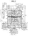
- the electric power line which is wired with the loop shape explained in Fig. 1 is connected to a load power supply shutdown circuit 110 of FIM 5 form the battery 3 through fusible links 4f and 4e.
- the power supply from the fusible link 4f is connected to the electric power line 12A via the load power supply shutdown circuit 110.
- the electric power line 12A is connected to one end of the electric power line 12B according to the connector 17A and another end is connected to a module side connector of a latter stated BCM to a load power supply shutdown circuit 210 of BCM 14.
- the electric power line 12B is connected electrically to the electric power line 12C in which one end is connected to a module side connector of a latter stated BCM via the load power supply shutdown circuit 210.
- Another end of the electric power line 12C is connected to one end of the electric power line 12D according to the connector 17B and is connected to a load power supply shutdown circuit 310 of RIM 29 via a latter stated module side connector of RIM.
- Another end of the electric power line 12D is connected electrically to the electric power line 12E in which one end is connected to a module side connector of a latter stated RIM via the load power supply shutdown circuit 310 of RIM 29.
- Another end of the electric power line 12E is connected to one end of the electric power line 12F according to the connector 17C and another end of the electric power line 12F is connected to the load power supply shutdown circuit 210 of BCM 14.
- Another end of the electric power line 12F is connected electrically to one end of the electric power line 12G via a module side connector of a latter stated BCM and another end of the electric power line 12G is connected to one end of the electric power line 12H according to the connector 17D and another end of the electric power line 12G is connected to the load power supply shutdown circuit 110 of FIM 5 via a module side connector.
- the power supply from the fusible link 4e is connected electrically to another end of the electric power line 12H through a latter stated module side connector via the load power supply shutdown circuit 110 of FIM 5, and as a result the electric power lines 12A - 12H are wired with the loop shape through the fuses 4e and 4f.
- this loop shape wired electric power line is given general name as a power bus 12.
- One example of the structure of these electric power lines 12A, 12B, 12C, 12D, 12E, 12F, 12G and 12H, as shown in Fig. 26, is constituted as a center of an electric power line 3020, an insulation member 3030 which covers a surrounding portion of the electric power line 3020, a conductive body 3010 which covers an outer periphery of the insulation member 3030 and an insulation material 3000 which covers an outer periphery of the insulation body 3010.
- the electric power line 3020 is made by a copper single wire or a copper twist wire and forms an power supplying use conductive line.
- the insulation member 3030 is made by an insulation body such as a rubber and a plastic and works to insulate the electric power line 3020.
- the conductive body 3010 is formed with a layer shape at an outer periphery of the insulation member 3030 by knitting together (hereinafter, a knit assembly wire) the thin copper wire.
- the insulation member 3000 is formed by an insulation body such as a rubber and a plastic and functions as a protection layer of a cable.
- a function of the above stated conductive body 3010 will be explained in detail in a latter portion and one end of the conductive body 3010 of the electric power line 12A is connected to a short detection circuit 230 of FIM 5 and another end presents an open state at the vicinity closed by the connector 17A.
- one end of the conductive body 3010 of the electric power line 12B is connected to the short detection circuit 230 of BCM 14
- one end of the conductive body 3010 of the electric power line 12C is connected to a short detection circuit 230 of BCM 14
- one end of the conductive body 3010 of the electric power line 12D is connected to a short detection circuit 330 of RIM 29
- one end of the conductive body 3010 of the electric power line 12E is connected to the short detection circuit 330 of RIM 29
- one end of the conductive body 3010 of the electric power line 12F is connected to the short detection circuit 230 of BCM 14
- one end of the conductive body 3010 of the electric power line 12G is connected to the short detection circuit 230 of BCM 14
- one end of the conductive body 3010 of the electric power line 12H is connected to the short detection circuit 130 of FIM 15, respectively.
- this conductive body 3010 is called as a short sensor.
- the electric power line 3020 starts from FIM 5 stated in above is connected to return with the loop shape via the electric power line 12A, the connector 17A, the electric power line 12B, BCM 14, the electric power line 12C, the connector 17B, the electric power line 12D, RIM 29, the electric power line 12E, the connector 17C, the electric power line 12F, BCM 14, the electric power line 12G, the connector 17D, and the electric power line 12H.
- the electric power lines 12A - 12H wired with the loop shape stated in above supply the power to the respective electric loads 190, 290 and 390 which are connected to the respective modules through the respective power supply shutdown circuits 110, 210 and 310 of the respective modules FIM 5, BCM 14 and RIM 29 and the respective load drive circuits (the driver circuits) 160, 260 and 360 of the respective modules FIM 5, BCM 14 and RIM 29.
- the power is supplied through the power supply supplying circuit 200 from the electric power lines 12B and 12G closed by the power supply among the electric power lines which are connected to the load power supply shutdown circuit 210 of BCM 14.
- a backup power supply is supplied from the power supply supplying circuit 200 of BCM 14 through the electric power line 50f.
- the load use electric power lines stated in above from the battery 3 to the control system use power supply is supplied to FIM 5, BCM 14 and RIM 29.
- the power supply is supplied to the control system use power supply circuit 320 of RIM 29 via the fuse 4d.
- the above stated power bus 12 supplies the power to the electric loads which are called as a body electric component system or the equipment system such as the control of the kinds of the head lamp, the stop lamp, the warning lamp, the power window, the door lock.
- the power is supplied to the injector for controlling the fuel injection amount and the ignition apparatus for controlling the ignition timing, an engine control module (ECM) for controlling the throttle valve opening degree, an automatic transmission (ATM) for carrying out the engine transmission, and a power train system power train control module (PCM), from the battery 3 via the fusible link 4a, the ignition switch 26a, the fuse 36b which are arranged in the vicinity of the dashboard, and the electric power line 50b.
- ECM engine control module
- ATM automatic transmission
- PCM power train system power train control module
- the power is supplied to ABS control unit 11 via the fusible link 4a, the ignition switch 26a, the fuse 36a in the fuse box 36, and the electric power line 50a.
- the power is supplied to the air bag control unit SDM 25 via the fusible link 4a, the ignition switch 26a, the fuse 36c in the fuse box 36, and the electric power line 50c.
- the power is supplied to the radio 15 via the fusible link 4a, the accessory switch 26b, the fuse 36d in the fuse box 36, and the electric power line 50d.
- the power is supplied to A/C unit 16 from the battery 3 via the fusible link 4a, the accessory switch 26b, and the fuse 36e in the fuse box 36.
- BCM 14 has the power supply supplying circuit 200, this power supply supplying circuit 200 is connected to the electric power lines 12B and 12G through the electric power lines 210b and 210g. Since the power is supplied to the radio 15, SDM 25, A/C 16 through the accessory switch 26b or the ignition switch 26a, when the accessory switch 26b or the ignition switch 26a presents an "off" state, the power is not supplied.
- the power for backing-up the data of these data is supplied from the power supply supplying circuit 200 of BCM 14 through the electric power line 50f. Since the data back-up use power supply is can be obtained by the power bus 12, it is unnecessary to provide the another back-up use separate electric power line and the fuse.
- the body electric component system module FIM 5, BCM 14, RIM 29, DDM 18 and PDM 20 has respectively the communication circuits 140, 240, 340, 640 and 540, and between the respective communication circuits is connected by the multiple communication line 30.
- the respective modules receives and sends mutually the input and/or output information which relates to the whole vehicle for example such as the condition of the ignition switch is inputted to BCM 14, according to the input signal which is taken into one module, the load which is provided to the another separate module can be drive-controlled.
- the power is supplied via from the power supply sullying circuit 200.
- the power supply circuit 500 and the power supply circuit 620 of the power supply circuit 520 of DDM 18 and the power supply circuit 620 of PDM is connected to respectively to the power supplying circuit 200 of BCM 14.
- the load group 290 which is connected to BCM 14 is received the power through an output circuit (a driver circuit) 260.
- the output circuit 260 is connected to the power supply units 12c and 12f through the electric power lines 120c and 120f.
- the output controls 260 receives the control signal from a control signal output signal line group 270b of the control circuit 270 and drives and control the load.
- the control circuit 270 output the load control signal to the output circuit 260 in accordance with the input signal which are inputted from the input circuit 250 and the input interface of the communication circuit 240, the ignition switch signal, the accessory switch signal and the receipt signal.
- BCM module 14 has a short detection circuit 230 and monitors a short abnormality of the electric power lines 12B, 12C, 12F and 12G.
- the short detection circuit 230 for example, when a short abnormally of the electric power line 12F is detected, such a signal is inputted into the control circuit 270, through an output signal line 270a the load power supply shutdown circuit 210 is driven, and an end portion of the power supply section 12F having the short abnormality is contacted and separated.
- control circuit 270 sends a signal which specifies the electric power line section having the short abnormality to other modules through the communication circuit 240.
- a predetermined module RIM 29 which has received the above stated signal controls a self load circuit 310 to separate the electric power line 12E which relates to the short abnormality through the self control circuit 370.
- the section 12F having the short abnormality and the electric power line 12E which is connected to the section 12F through the connector 17C are separated from the loop shape electric power line, after that according to the tree connection line which are comprised of the main line having the electric power lines 12A, 12B, 12C and 12D and the sub-lines 23, 24 and 50f which are wired from the power supply circuit 200 of BCM module 14, the power is supplied to the respective loads.
- FIM module 5 has a short detection circuit 130 and monitors a short abnormality of the electric power lines 12A an 12H.
- the short detection circuit 130 for example, when a short abnormally of the electric power line 12A is detected, such a signal is inputted into the control circuit 170, through an output signal line 170a the load power supply shutdown circuit 110 is driven, and an end portion of the electric power line section 12A having the short abnormality is contacted and separated.
- control circuit 170 sends a signal which specifies the electric power line section having the short abnormality to other modules through the communication circuit 140.
- the control circuit of BCM module 14 which has received the above stated signal drives the load power supply shutdown circuit 210 through the output signal line 270a and accordingly another end portion of the electric power line 12B which is connected through the electric power line 12A and the connector 17A is released.
- the power is supplied to the respective loads.
- the tree connection line which are comprised of the main line having the battery 3, the fuse 4e, the load power supply shutdown circuit 110 of FIM module 5, the electric power lines 12H and 12G, and the load shutdown circuit 310 having BCM module 14, and the sub-lines 23, 24 and 50f which are wired from the power supply circuit 200 of BCM module 14, the power is supplied to the respective loads.
- Fig. 3 shows a construction of another embodiment. The portions which differ from the construction shown in Fig. 2 will be explained.
- Fig. 2 the separate system power supply system which has the separate function except for the body electric component system is shown, however in the embodiment shown in Fig. 3, the power supply supplying to the power train control module (PCM) 10 and ABS control unit 11 is carried out from the power supply supplying circuit 100 of FIM 5 which is arranged in the same engine room and to the radio 15 and the SDM 25, and A/C unit 16, the power supply is supplied from the power supply supplying circuit 100 of BCM 14 which is arranged in the same cabin.
- PCM power train control module
- Fig. 4 shows a construction of a further embodiment. The portions which differ from the construction shown in Fig. 2 will be explained.
- the modules which is connected to the power bus 12 are three which are FIM 5, BCM 14 and RIM 9, in Fig. 4, the power train control module (PCM) 10 which is the control system module having the separate function except for the body electric component system, ABS control unit 11, and A/C unit 16 are connected to the power bus 12.
- PCM power train control module
- the power bus is comprised of FIM 5, an electric power line 12A1, ABS 11, an electric power line 12A2, a connector 17A, the electric power line 12B, BCM 14, the electric power line 12C, a connector 17B, the electric power line 12D, RIM 29, the electric power line 12E, a connector 17C, the electric power line 12F, A/C unit 16, the electric power line 12G, a connector 17D, an electric power line 12H2, PCM 10, an electric power line 12H1, FIM 5.
- control system power supply is supplied through the respective fuse 4g, the fuse 4a, the fuse 4h and further the multiple communication line 30 is connected.
- the power supply supplying to DDM is altered from BCM 14 to A/C unit 16.
- the power supply supplying circuit to FIM 5 and BCM 14 can be simplified.
- Fig. 5, Fig. 6, Fig. 7, Fig. 8, and Fig. 9 are the constructions of the embodiment shown in Fig. 2.
- the load power supply shutdown circuit 110 shown in Fig. 2 is constituted by a first load power supply shutdown circuit 110a and a second load power supply shutdown circuit 110b.
- the first load power supply shutdown circuit 110a is constituted by a relay 111 and a diode 113, and a semiconductor switching element 115.
- the second load power supply shutdown circuit 110b is constituted with same of the first load power supply shutdown circuit 110a and is constituted by a relay 112 and a diode 114, and a semiconductor switching element 116.
- first and the second load power supply shutdown circuits 110a and 110b Since the operation and the detailed construction of the first and the second load power supply shutdown circuits 110a and 110b are same, it will be explained by the first load power supply shutdown circuit 110a.
- the power supply supplying to the coil of the relay 111 is connected to the control system power supply explained in Fig. 2, on an end portion of the contact point of the relay 111 is connected to the battery 3 through the fusible link 4f and another end portion is connected to the loop system power supply supplying system electric power line 12A, at the same time it is connected to the output circuit 160 for supplying the power supply supplying to the load.
- the power supply to the coil of the relay 111 is carried out from the control system power supply and further the power supply supplying to the control 170 for outputting the control signal of the coil, even if the power bus 12 is carried out the fail, and the control of the relay 111 is carried out and accordingly the shutdown and connection of the first load power supply shutdown circuit 110a can be carried out.
- the current for flowing the relay 111 is performed the shutdown, since the power supply for supplying the load can be performed the shutdown, the consumption current can be lessened.
- the output circuit 160 is constituted by semiconductor switching elements 163 - 168 which carry out the drive control by supplying the power supply to the over-current detection circuits 161 and 162 and the loads.
- semiconductor switching elements 163 - 168 power MOSFET which is installed an over-temperature detection shutdown function in an interior portion is used, and when the over-current flows and the temperature of the element becomes to more than a predetermined temperature, it presents to an "off" state.
- a washer motor 191 to the semiconductor switching elements 163, 164 and 165, a washer motor 191, a turn lamp right 7a, and a head lamp right 6 which are arranged respectively at a right side of a vehicle of the load 190 which is connected to FIM 5.
- a horn 8 To the semiconductor switching elements 166, 167 and 168, a horn 8, a turn lamp left 2a, and a head lamp left 1 which are arranged respectively at a right side of a vehicle of the load 190 which is connected to FIM 5.
- the semiconductor switching elements 163, 164 and 165 are connected to the over-current detection circuit 161 and to another end of an upstream of the over-current detection circuit 161, the power supply is supplied from the second load power supply shutdown circuit 110b.
- the other ends of the semiconductor switching elements 166, 167 and 168 are connected to an over-current detection circuit 162 and to another end of an upstream of the over-current detection circuit 162 the power supply is supplied from the first load power supply shutdown circuit 110a.
- the separate systems are formed, even any one of the separate systems becomes the fail, another separate system can be operated.
- the reason why the separate system is formed at the right side and at the left side is that to FIM 5, many loads constituted one pair at the right side and the left side, for example, the head lamp, the fog lamp, the clearance lamp etc. are connected.
- the control system power supply circuit 120 is constituted by a diode 122, a constant voltage power supply circuit 121, and a power supply shutdown circuit.
- the control system power supply which is supplied from the battery 3 through the fuse 4b supplies to the constant voltage power supply circuit 121 via the diode 122.
- the constant voltage power supply circuit 121 it is generated a constant voltage which operates the control circuit 170 for carrying out the various kinds executions and the control processing. This voltage is supplied to a voltage application drive circuit 131 of the short detection circuit 130 and the control 170, the communication circuit 140, and the power supply shutdown circuit 123.
- the constant voltage power supply which is supplied from the constant voltage power supply circuit 121 is supplied and is performed the shutdown to the input circuit 150.
- the input circuit 150 converts the signal of the atmospheric temperature sensor 181 of the input signal 180 and the brake liquid amount sensor 182 etc. to the voltage in which the above stated signal is taken into the control circuit 170.
- resistors 151 and 152 it is carried out to a pull-up.
- the pull-up resistors 151 and 152 when the man does not ride on the vehicle and the vehicle is left alone, according to the information from the brake liquid amount sensor 182 and the atmospheric temperature sensor 181, in regardless of the necessity for alarming the alarm etc., via the pull-up resistors 151 and 152, when the current flows into the brake liquid amount sensor 182 and the atmospheric temperature sensor 181, the battery 3 is discharged and then the battery 3 comes to an end.
- the power supply for supplying to the pull-up resistors is performed the shutdown according to the power supply shutdown circuit 123.
- the short detection circuit 130 is constituted by a voltage application drive circuit 131, pull-up resistors 132 and 135, and pull-down resistors 133, 134 to the ground.
- the voltage application drive circuit 131 carried out to an "on” state and an “off” state of the power supply supplying to the pull-up resistors 132 and 135 according to the control signal of the control circuit 170.
- the pull-up resistor 132 and another end of the pull-down resistor 133 are connected to an outside of FIM 5 through a connection use connector for the outside of FIM 5 and further are connected to a short sensor of the electric power line 12H.
- control signal is inputted to the control circuit 170.
- the pull-up resistor 135 and another end of the pull-down resistor 134 are connected to an outside of FIM 5 through a connection use connector for the outside of FIM 5 and further are connected to a short sensor of the electric power line 12A.
- control signal is inputted to the control circuit 170. Further, in an interior portion of FIM 5, the control signal is inputted to the control circuit 170.
- the reason why the pull-up resistor 135 and another end of the pull-down resistor 134 are connected to the outside of FIM 5 through a connection use connector for the outside of FIM 5 is as following.
- connection portion is oxidized and there is a possibility of a contact fail.
- Fig. 6 is a construction view of BCM 14.
- the first load power supply shutdown circuit 210a shown in Fig. 2 and the second load power supply circuit 201b have the same constructions of the first load power supply shutdown circuit 110a shown in Fig. 2 and the second load power supply circuit 110b.
- the power supply supplying of a coil of a relay 211 is connected to the control system power supply and one end of a contact of the relay 211 is connected to the loop system power supply supplying system electric power line 12B and another end is connected to the loop system power supply supplying system electric power line 12C and the same time both ends are connected to the power supply supplying circuit 200 for supplying the power supply to the loads or the output circuit 260.
- the output circuit 260 and the power supply supplying circuit 200 have the differ names however since the function, the construction are the same, it will be explained simultaneously.
- the output circuit 260 and the power supply supplying circuit 200 are constituted by the over-current detection circuits 261, 262, 201 and 202 and the semiconductor switching elements 263-266, 203 and 204 for carrying out the drive by supplying the power supply to the loads.
- the power MOSFET to which the over-temperature detection shutdown function is installed is used, and when the over-current flows and the temperature of the element becomes more than a predetermined temperature, it presents to an "off" state.
- DDM 18 which is arranged to the driver seat door and to the semiconductor switching element 204, PDM 20 which is arranged to the passenger seat door.
- the semiconductor switching elements 263 and 264 are connected to the over-current detection circuit 261 and to another end of an upstream of the over-current detection circuit 261, the power supply is supplied from the second load power supply shutdown circuit 110b from the electric power line 12F.
- the other ends of the semiconductor switching elements 265 and 266 are connected to an over-current detection circuit 262 and to another end of an upstream of the over-current detection circuit 262 the power supply is supplied from the first load power supply shutdown circuit 110a from the electric power line 12C.
- the other ends of the semiconductor switching element 203 is connected to the over-current detection circuit 261 and to another end of an upstream of the over-current detection circuit 201 the power supply is supplied from the first load power supply shutdown circuit 110a from the electric power line 12G.
- the other ends of the semiconductor switching element 204 is connected to the over-current detection circuit 202 and to another end of an upstream of the over-current detection circuit 202 the power supply is supplied from the first load power supply shutdown circuit 210a from the electric power line 12B.
- the control system power supply circuit 220 has the same construction and the same operation with the control system power supply circuit 120 of FIM 5 shown in Fig. 5.
- the input circuit 250 converts the signals from the intermittent wiper volume 282 of the input signal 280, the wiper switch 283, the light switch 281, and the ignition key switch (not shown in Fig. 6) etc. to the voltage in which the above stated signals are taken in the control circuit 270.
- the pull-up function is added by the resistors 251, 252 and 253.
- the load to be controlled operates necessarily only when the ignition switch is presented to the "on" state, when the man does not exist in the vehicle and the vehicle is left alone, since it is unnecessary to take in the information, the power supply which is supplied to the pull-up resistors 251 and 252 is shutdown by the power supply shutdown circuit 123.
- the power supply supplying of the pull-up resistor 253 is connected to the output of the constant voltage power supply circuit 221 in which the power supply supplying is carried out always.
- the short detection circuit 230 is connected to four short sensors of the electric power line 12B, the electric power line 12C, the electric power line 12F, and the electric power line 12G.
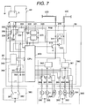
- Fig. 7 is a construction view of RIM 29.
- the construction of the load power supply shutdown circuit 310 is the same construction of the construction of the load power supply shutdown circuit 110a of FIM 5 shown in Fig. 5 and the power supply supplying of a relay 311 to a coil is connected to the control system power supply explained in Fig. 2.
- a contact of the relay 311 is connected to the loop system power supply supplying system electric power line 12D and another end is connected to the loop system power supply supplying system electric power line 12E and at the same time the both two ends are connected to the output circuit 360 for supplying the power supply to the loads.
- the output circuit 360 is constituted by semiconductor switching elements 364 - 368 which carry out the drive control by supplying the power supply to the over-current detection circuits 361 and 362 and the loads.
- the power MOSFET which is installed an over-temperature detection shutdown function in an interior portion is used, and when the over-current flows and the temperature of the element becomes to more than a predetermined temperature, it is presented to an "off" state.
- a power window motor 391 of a rear seat right side door of the load 390 is connected to RIM 29, a fuel pump 392 which is arranged at a right side of the trunk room, a stop lamp right 393 etc. are connected.
- a power window motor 394 of a rear seat left side door of the load 390 is connected to RIM 29, a fuel pump 395 which is arranged at a left side of the trunk room, and a stop lamp left 396 etc. are connected.
- the semiconductor switching elements 363, 364 and 365 are connected to the over-current detection circuit 361 and to another end of an upstream of the over-current detection circuit 361, the power supply of the load power supply shutdown circuit 310 is supplied from the electric power line 12D.
- the other ends of the semiconductor switching elements 166, 167 and 168 are connected to an over-current detection circuit 162 and to another end of an upstream of the over-current detection circuit 162 the power supply of the load power supply shutdown circuit 310 is supplied from the electric power line 12D.
- the reason why the separate system is formed at the right side and at the left side is that to RIM 29, many loads constituted one pair at the right side and the left side, for example, the stop lamp, the table lamp etc..
- the semiconductor switching elements 363 and 366 is H bridge circuit which drives the motor toward the both normal and reverse directions, such a construction will be explained in a latter portion.
- the control system power supply circuit 320 has the same construction and the same operation with the control system power supply circuit 120 of FIM 5 shown in Fig. 5.
- the input circuit 350 converts the voltage in which the control circuit 370 takes in the signals from the door opening and closing switch 382 of the input signal 380 and the rear seat power window switch 383 etc..
- the resistors 351 and 352 are formed to make the pull-up.
- the power supply which is supplied to the pull-up resistors 351 and 352 is shutdown by the power supply shutdown circuit 323.
- the short circuit 330 is connected to two short sensors of the electric power line 12D and the electric power line 12E.
- Fig. 8 is the construction of PCM 10 in which the power supply is supplied according to another system against the loop shape power supply supplying system.
- PCM 10 according to embodiment shown in Fig. 2 is constituted by a power supply circuit 720, a control circuit 770, an input circuit 750, and an output circuit 760.
- the power supply circuit 720 is constituted by a diode 722, and a constant voltage power supply circuit 721.
- the power supply which is supplied from the battery 3 via the fuse 4a, the ignition switch 26a, and the fuse 36b is supplied to the constant voltage power supply circuit 721 via the diode 722, on the other hand as the load drive use power supply the power supply is supplied to the semiconductor switching elements 761 and 765 of the output circuit 760.
- the input circuit 750 converts to the voltage in which the control circuit 770 takes into the signals from the crank angle sensor 781, the air flow sensor 782, and the throttle sensor 783, etc..
- the output circuit 760 is constituted by semiconductor switching elements 761 and 765 which carry out the drive control by supplying the power supply to the loads and semiconductor switching elements 762, 763 and 765 which carry out the "on” and “off” operations of the loads.
- the power MOSFET which is installed an over-temperature detection shutdown function in an interior portion is used, and when the over-current flows and the temperature of the element becomes to more than a predetermined temperature, it is presented to an "off" state.
- the semiconductor switching elements 762, 763 and 765 a simple semiconductor switching element is used. Because, the load becomes the short and the current flows, since the fuse which is arranged at the upstream of the load is welded, the over current does not continue to flow.
- the semiconductor switching element having no protection function is used, naturally there is no problem in which the semiconductor switching element having the protection function is used.
- a warning lamp 792 of the load 790 which is connected to PCM 10 an injector 793, the EGR solenoid 794 are connected, and at the upstream of these elements the fuses 36f, 36g and 36h are connected.
- an injector 793, the EGR solenoid 794 are connected to the semiconductor switching element 761, AT solenoid 791 of the load 790 which is connected to PCM 10 etc. are connected.
- the semiconductor switching element 765 is H bridge circuit which drives the motor toward the both normal and reverse directions, such a construction will be explained in a latter portion.
- ABS 11 the separate system with the loop shape power supply supplying system shown in Fig. 2, the explanation about of the constructions of ABS 11, A/C 16, SDM 25, the radio 15 are substantially to the same of PCM 10 shown in Fig. 8 will be omitted, naturally the input signals and the loads which are connected to the modules differ.
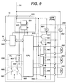
- Fig. 9 shows a construction view of DDM 18 in which the power supply is supplied to from the power supply supplying circuit 200 of BCM 14.
- DDM 18 is constituted by a power supply circuit 620, a communication circuit 670, and a part of an output circuit 660 and a part of the loads 690.
- the power supply circuit 620 is constituted by a constant voltage power supply circuit 621 and a power supply shutdown circuit 623.
- the power supply which is supplied from the constant voltage power supply circuit 621 and the power supply shutdown circuit 623.
- the power supply which is supplied from the power supply supplying circuit 200 from BCM 14 is supplied to the constant voltage supply circuit 721 and one other hand, as the load use drive use power supply, to the switching elements 663, 664, and 665 and the load 691 is supplied.
- the constant voltage power supply circuit 621 the constant voltage for operating the various kinds executions and the control processing is generated.
- the input circuit 650 it is converted to the voltage for taking into the signals from the power window switch 681 and the door lock switch 682.
- the output circuit 660 is constituted by semiconductor switching elements 663, 664 and 665 which carry out the drive control by supplying the power supply to the loads and semiconductor switching elements 661 and 662 which carry out the "on” and “off” operations of the loads.
- the semiconductor switching elements 661 and 662 a simple semiconductor switching elements are used.
- the semiconductor switching element having no protection function is used and however there is no problem in which the semiconductor switching element having the no protection function is used.
- the switching elements 663, 664 and 665 for driving the power window motor 693, the door lock motor 694, the mirror motor 695 use the relay, however the semiconductor switching element can be employed.
- a switch mirror lamp 691 of the load which is installed in the interior portion of DDM 18 is connected to, and to the semiconductor switching element 662, a step motor which is installed to the door is connected, and at the upstream of these loads the power supply supplying circuit 200 of BCM 14 is connected.
- PDM 20 Since the construction of PDM 20 is substantially to the same of DDM 18 shown in Fig. 9, the explanation will be omitted.
- the diameter of the wire can be formed thin. Further, as the semiconductor switching element used in the output circuit, it can be employed the element having no protection function.
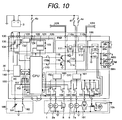
- Fig. 10, Fig. 11 and Fig. 12 are construction views of FIM 5, BCM 14 and PCM 10 according to the embodiment shown in Fig. 3, however there are no changes in other modules RIM 29, DDM 18 and PDM 20 against the embodiment shown in Fig. 2.
- the separate system power supply system having the separate function except for the body electrical component system is formed every the control system each, however the construction according to the embodiment shown in Fig. 3, the power supply to PCM 10 and ABS 11 is supplied from FIM 10 which is arranged in the same engine room. Accordingly, a power supply supplying circuit 100 is added against FIM 5 shown in Fig. 5.
- the semiconductor switching element 102 of the power supply supplying circuit 100 receives the supply of the power supply via an over-current detection circuit 162 and controls the supply of the power supply against PCM 10, and the semiconductor switching element 101 receives the supply of the power supply via an over-current detection circuit 161 and controls the supply of the power supply against ABS 11.
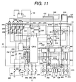
- BCM 14 The construction of BCM 14 according to the embodiment shown in Fig. 3 will be explained according to Fig. 11. Only the different points against to the construction of BCM 14 according to the embodiment shown in Fig. 6 will be explained.
- the separate system power supply system having the separate function except for the body electrical component system is formed every the control system each, however the construction according to the embodiment shown in Fig. 3, the power supply to the radio 15, SDM 25 and A/C 16 is supplied from BCM 14 which is arranged in the same cabin of the vehicle.
- the supply of the power supply is controlled according to the semiconductor switching elements not shown in figure to the power supply supplying circuit 200.
- PCM 10 The construction of PCM 10 according to the embodiment shown in Fig. 3 will be explained referring to Fig. 12.
- the construction of PCM 10 is the same shown in Fig. 8, however the power supply supplying of PCM 10 and the loads is altered from FIM 5.
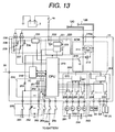
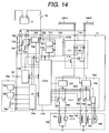
- Fig. 13 and Fig. 14 are construction views of the modules BCM 14 and PCM 10 according to the embodiment shown in Fig. 4, however there are no changes in other modules FIM 5, RIM 29, DDM 18 and PDM 20 against the embodiment shown in Fig. 2.
- SCM 14 according to the embodiment shown in Fig. 4 will be explained according to Fig. 13. Only the different points against to the construction of BCM 14 according to the embodiment shown in Fig. 6 will be explained.
- the modules connected to the power bus 112 are three which are FIM 5, BCM 14, RIM 29, however in Fig. 4 the control modules having the separate function except for the body electrical component system which are PCM 10, ABS 11 and A/C 16 is connected to the power bus 12.
- the electric power lines connected to BCM 14 are two which are the electric power line 12B and the electric power line 12C and the electric power line 12F, the electric power line 12G which are connected in the embodiment shown in Fig. 2 are connected to A/C 16.
- the power supply supplying circuit of BCM 14 can be simplified.
- PCM 10 The construction of PCM 10 according to the embodiment shown in Fig. 4 will be explained referring to Fig. 14.
- PCM 10 which is the control system module having the separate function except for the body system electric equipment system is connected to the power bus 12.
- PCM 10 shown in Fig. 14 differs from the construction of RIM 29 which is connected to the power bus 12 as shown in Fig. 2 from the aspects of the input signals to be connected and the electric power lines, however the construction has basically the same construction. Accordingly, the detailed constructions and the operation explanation will be omitted.
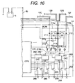
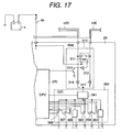
- Fig. 15, Fig. 16 and Fig. 17 are other constructions of Fig. 5.
- the power supply which is supplied from more than two electric power lines of the loop system power supply system which is connected to the module is supplied independently respectively to the loads.
- the power supply which is supplied from more than two electric power lines of the loop system power supply system is supplied to the loads in the interior portion of the module by performing the diode logical AND.
- the power supply from the electric power line 12A and the electric power line 12H is supplied to the output circuit by performing the logical AND in a diode 117 and a diode 118.
- the power supply from the electric power line 12B and the electric power line 12C is supplied to the output circuit by performing the logical AND in a diode 217 and a diode 218 and the power supply from the electric power line 12F and further the electric power line 12G is supplied to the output circuit by performing the logical AND in a diode 219a and a diode 219b.
- the power supply from the electric power line 12D and the electric power line 12E is supplied to the output circuit by performing the logical AND in a diode 317 and a diode 318.
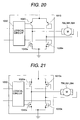
- a logical circuit 1050 converts to a control signal of H bridge which is constituted by four semiconductor switching elements 1010, 1020, 1030 and 1040 having no short protection function.
- the semiconductor switching elements 1020 and the semiconductor switching elements 1030 are presented to the "on" state and to a motor 1060 the current is flown, and during the reversal rotation, the semiconductor switching elements 1010 and the semiconductor switching elements 1040 are presented to the "on” state and it converts the signal for flowing the reversal current into the motor 1060.
- the upstream side two semiconductor switching elements which constitute H bridge are formed with semiconductor switching elements 1010a and 1020a having the short protection function and in the construction shown in Fig. 20, the downstream side two semiconductor switching elements which constitute H bridge are formed with semiconductor switching elements 1030a and 1040a having the short protection function.
- the upstream side and the downstream side all of four semiconductor switching elements which constitute H bridge are formed with semiconductor switching elements 1010a, 1020a, 1030a and 1040a having the short protection function.
- PCM 10 (Fig. 8) and ABS 11, A/C 16 etc. according to the embodiment shown in Fig. 2 have the fuses every functions each and every loads each as shown in PCM 10 shown in Fig. 8, even the apparatus has not H bridge circuit having the short protection function, since it does not present the fatal fail.
- H bridge circuit having no short protection function shown in Fig. 18 is used.
- H bridge circuits shown in Fig. 19, Fig. 20, Fig. 21 are used.
- Fig. 22 shows the construction of the over-current detection circuit.
- An one end at the upstream side shunt resistor 2020 is connected to the electric power line and one end at the downstream side shunt resistor is connected to the plural semiconductor switching elements for driving the loads and further all of the currents which flow into the connected loads flow this shunt resistor 2020.
- a potential difference between the both ends of the shunt resistor 2020 is amplified according to an amplification circuit 2010 and the current which flows into the shut resistor 2020, namely a total sum of the currents which flow into the load to be connected, is detected according to A/D converter 2000 of the control circuit.
- the fail-safe operation in accordance with the detection of the current, the dead short fail of the load, the leak short fail of the load, the complex fail of the load dead short fail and the dead short fail of the semiconductor switching element of the output circuit etc. are detected, accordingly the fail-safe operation can be carried out.
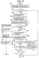
- Fig. 37 shows the above stated fail detection manner of the load and a fail safe manner.
- the current IT which flows into the over-current detection circuit is measured by A/D converter 2000 shown in Fig. 22.
- a step 6001 the current IT which was measured is judged that whether the Current is more than a predetermined tolerance value or not.
- the above stated tolerance value is a numeric value that this value is less than a value in which when the current flows more than the tolerance value, any portion of the module is destroyed and this numeric value is established to be more than the current value in which all loads connected to the module operate.
- step 6010 when the current IT is judged less than the tolerance value, it is judged that there is no fatal dead short fail, and a step 6200 shown in Fig. 38 is carried out.
- step 6010 when the current IT is judged more than the tolerance value, any load is assumed to become the short, and after steps including a step 6020 are carried out.
- a step 6020 since all of the loads which are presented to the "on” state present to be the “off” state, all of the semiconductor switching elements of the output circuit are presented to the "off” state.
- a step 6030 a number m of the loads which have presented at the "on” state is calculated and in a step 6040, the current IT is measured again.
- a step 6050 it is compared that whether the current IT to be measured again (the current during all of the semiconductor switching elements presenting to the "off" state) exceeds the above stated tolerance value or not.
- the loop system power supply system is not to supplied the power supply to the fail point, firstly in a step 6150, to perform the "off" state of the load power supply shutdown circuit of the module which is connected to the power supply system which has presented to the fail, in a step 6160, the fail information is sent to other module via a multiple bus.
- a step 6170 the fail point and the contents of the fail are displayed and further it stores as the service information to the dealer. This stored information can be read out according to the diagnosis apparatus shown in Fig. 1, etc..
- step 6050 When the current IT which has measured again in the above stated step 6050 is less than the tolerance value, the semiconductor switching element is not the fail but any load is presented to the dead short. In after the steps including a step 6060, it is judged that any load is presented to the short.
- a numeric value n for indicating what time repetition of a following processing is initialized to be "1".
- a step 6070 after only one load which has presented to the "off” state is presented to the "on” state, in a step 6070, the current IT during this time is measured and in a step 6090, the current IT in this time is compared with the above stated predetermined tolerance value.
- a step 6090 the current value IT is less than the predetermined tolerance value, then it is judged that the load is not presented to the dead short, in a step 6100, the semiconductor switching element for driving the load is presented to the "on" state, then it is performed as the normal operation.
- n is performed to increase by "1"
- a step 6140 it is compared that whether all processing have finished or not, and when the steps have not finished, the processing after the steps including a step 6070 are repeated and then when the steps have finished, a step 6200 shown in Fig. 38 which is a next processing is carried out.
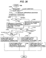
- Fig. 38 shows a process for performing the "off" state the loads according to the detection in which the current having more than a normal value is detected by the leak of the load but not according to the detection of the dead short.
- a step 6210 the current value IT is measured.
- a step 6220 the maximum current value ILmax and the minimum current value ILmin of all the loads at the normal time which operate during the current value IT measurement are searched, and further a number m of the operated loads is calculated.
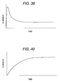
- Fig. 39 shows an example of a center value of the current at the normal time of the lamp from the operation starting
- Fig. 40 shows an example of a center value of the current at the normal time of the motor from the operation starting.
- the current data of all of the loads at the normal time have stored in advance in a memory, and the data is searched and the scattering data is added to the searched center value, in a following formula 1 and a following formula 2, the maximum current value ILmax and the minimum current value ILmin of all the loads at the normal time are calculated.
- ILmax current at normal time x (1 + ⁇ )
- ILmin current at normal time x (1 - ⁇ )
- ⁇ indicates a scattering degree
- a total sum ITmax of the maximum current value and a total sum ITmin of the minimum current value of the current value at the normal time of the loads which have presented to the "on" state are calculated according to a following formula 3 and a following formula 4.
- the abnormality judgement maximum current value INGmax is calculated according to a following formula 5 and the abnormality judgement minimum current value INGmin is calculated according to a following formula 6.
- INGmax ITmax + A
- INGmin ITmin - A
- Reference numeral "A" in the formula 5 and 6 is a predetermined constant value having more than zero (0).
- the calculation about the abnormality judgement current value is calculated by adding the predetermined constant value, however it may be requested according to the proportion calculation.
- the current value IT measured in a step 6210 and the abnormality judgement current value calculated in a step 6240 are compared in a step 6250.
- the current value IT is larger than the abnormality judgement minimum current value INGmin and is less than the abnormality judgement maximum current value INGmax, since it shows the normal, the processing is finished.
- a numeric value n which the following processing are repeated what times is initialized to be "1".
- a step 6270 after 1 ms where one load which has presented to the "on” state is performed to the "off” state, in a step 6270, the current ITnew at this time is measured.
- a step 6290 when the varied current value (IT - ITnew) according to the "off" state is smaller than the maximum current value ILmax of the load which was requested by the search in the step 6220 and is larger than the maximum current value ILmin, the load is normal, and then in a step 6300, the semiconductor switching element for driving the load is performed to the "on" state, and it made to be the operation at the normal time.
- a step 6290 it is judged as the load abnormality, regardless the return condition is effected the load is performed to the "off" state. Further, in a step 6320, the fail information is displayed and stored.
- n is performed to increase by "1"
- a step 6340 it is compared that whether all processing have finished or not, and when the steps have not finished, the processing after the steps including a step 6270 are repeated.
- the protection function of the semiconductor switching element can be performed to have the over-current limitation function having large scattering only to aim not to destroy the semiconductor switching element and the short protection can be carried out fully, accordingly the construction of the semiconductor switching element can be simplified.
- Fig. 23 shows another embodiment of the over-current detection circuit and the different points in the construction shown in Fig. 22 is that a fuse is connected to a shunt resistor 2020 in series.
- the fail detection and the fail safe processing shown in Fig. 37 and Fig. 38 are carried out, and further when the failed power system is not performed the shutdown even the failed power system is performed the shutdown, since the fuse 2030 is fused, the fail point can be performed the shutdown.
- Fig. 24 shows a further another embodiment of the over-current detection circuit, and the different points shown in Fig. 22 is that a protection element (hereinafter, PTC element) 2220 having PTC characteristic (the characteristic when the temperature is risen, the resistance is increased) in place of the shunt resistor 2010.
- PTC element protection element
- PTC element has the temperature characteristic as shown in Fig. 25(a) and when the temperature of the element is risen more than some temperature (in this embodiment about 120°C), the resistance value increases abruptly.
- the resistance value having about several ten m ⁇ of PTC element in this embodiment increases the temperature having from about several ten k ⁇ to about several hundred k ⁇ .
- the factor in which the temperature raises is the current which flows into PCT element, and a relationship between the current and a time (a trip time) for increasing abruptly the resistance value is shown in Fig. 25(b).
- the characteristics 2310, 2320 and 2340 are the characteristics when the respective surrounding temperatures are 0°C, 20°C and 60°C, respectively, at the time of the current having more than 15A, the characteristic is that the resistance value increases less than one second.
- the power bus 12 which makes a round in the vehicle is installed, when the electric power line becomes the short circuit in the vehicle, the power supply is not supplied to all of modules and then almost all functions of the automobile are made to stop.
- One construction elements of the above stated treatments is the electric power line having the above stated short sensor.
- the embodiment of the electric power line three kinds of the constructions shown in Fig. 26, Fig. 27 and Fig. 28 are shown.
- a connector 3050 is employed to connect to the module.
- a rubber plug 3080 has a role of the water proof.
- the electric power line 3020 is connected to a terminal 3060 with a faucet manner and is connected to the connector of the module with the fitting.
- a short sensor 3010 made by a connector for shield is connected to a terminal 3070 with a faucet manner and is connected to the connector of the module with the fitting-into.
- the short sensor constituted by the connector for shield is constituted by an aluminum film 3010a and a drain wire 3010b which contacts to an inner side of the aluminum film.
- the conductive body can be formed at all faces, even the contact with the material such as a needle, the short can be detected, accordingly the detection performance as the short sensor can be improved.
- the construction shown in Fig. 28 is a construction in which the drain wire 3010b shown in Fig. 27 is deleted.
- a connector 3050a for connecting the short sensor to the module is constructed with the connector as one body as shown in figure.
- the connector 3070a is buried with a cylindrical form at an inner periphery of a harness side of the connector 3050a and is formed with a portion for connecting the module as one body and further has the same potential.
- the short sensor 3010 of the electric power line is connected to a faucet portion of another relay terminal 3080 with a faucet manner.
- a faucet portion of the short sensor a portion having a spring force to connect according to a contact with the terminal 3070a and a portion for connecting the two portions are formed as one body.
- the procedure of the process is that firstly the terminal 3060 and the electric power line 3020 are connected to with the faucet manner, the short sensor 3010a and the relay terminal 3080 are connected to with the faucet manner, and the faucet member is inserted to the connector 3050a. In the short sensor, between the relay terminal 3080 and the terminal 3070a is connected with the connection manner.
- the structure of the electric power line can be simplified, and further the terminal process of the short sensor can be simplified.
- a control signal of a voltage application drive circuit 131 is controlled with a pulse shape waveform as shown in the drive signal shown in Fig. 29, in the normal time the waveform having the same drive signal is inputted in a control circuit 170, when it is performed the short to the ground (hereinafter a lower side short), the waveform which is originally to be a high potential becomes a low potential.
- the waveform which is originally to be a low potential becomes a high potential.
- this logic it can be detected that whether the short sensor is the lower side short or is the upper side short.
- the short sensor since the short sensor has an open condition at portions of the connectors 17A, 17B, 17C and 17D, it can detect that in FIM 5, the lower side short and the upper side short of the electric power lines 12A and 12H, in BCM 14, the lower side short and the upper side short of the electric power lines 12B, 12C, 12F and 12G, in RIM 29, the lower side short and the upper side short of the electric power lines 12D and 12E and then the fail point can be specified.
- the electric power lines 12B, 12C, 12F and 12G are separated in the cabin, the electric power lines 12D and 12E are separated in the trunk room, in a case of a mending of the fail point, it can be constituted to mend only one harness.
- the functions of the load power supply shutdown circuit as explained in the above stated construction shown in Fig. 37, there are functions which are the function for separating the fail point from the power bus 12 during the dead short of the load and during the dead short of the output circuit, the fail safe function for separating the fail point from the power bus 12 by detecting beforehand the upper side short and the lower side short of the electric power line which will be explained in a latter portion, and the sleep function for reducing the consumption current by carrying out the shutdown the power supply supplying when the man does not exist in the vehicle and the vehicle is left alone.
- a step 5000 it is judged that whether it is the sleep condition where the man does not exist in the vehicle and the vehicle is left alone or whether the normal operation condition, for example, when the ignition switch is presented to the "on” state and the accessory switch is presented to the "off” state, and the all of doors are the closing conditions, and there is no load being operated, it is judged as the sleep condition.
- the load power supply shutdown circuit is performed the shutdown, and the power supply supplying to the loads is performed the shutdown.
- a relay is employed, and this relay is that the connection is carried out when the current is continued to flow the load.
- the battery is discharged.
- the current does not flow into the coil of the relay and the leakage current of the semiconductor switching element which is employed in the output circuit does not flow, accordingly the consumption of the current can be restrained.
- the power supply for the coil of the relay and the control system power supply are formed with the separate power supplies against the power bus 12, even when the load power supply shutdown circuit is performed the shutdown, the control circuit can be operated.
- a step 5010 in all of the modules which are connected to the power bus 12, the diagnosis for the power bus is carried out.
- the short detection manner As the diagnosis manner, the short detection manner according to the short sensor stated in above is carried out. As the diagnosis for the power bus, the aim will be attained using the current detection manner.
- the fail information such as the fail point and the fail contents etc. is displayed, and it is stored in the memory, in a step 5040, the connection and the shutdown of the load power supply shutdown circuit of the respective modules is carried out as shown in the logical value table shown in Fig. 31 in response to the fail point.
- the failed point electric power line 12A and the electric power line 12B which is connected directly by the connector 17A are performed completely the shutdown according to the power bus 12.
- the electric power line 12C is performed the shutdown according to the power bus 12, however since the relay of the load power supply shutdown circuit 310 of RIM 29 which has performed the shutdown during the normal time is connected, the power supply is supplied from the reverse direction against the normal time.
- the loads in this embodiment, only the head lamp left 1, the turn lamp left, the horn 8, PDM 20, which are received the supply of the power supply from the electric power line, can not be operated.
- the failed point electric power line 12A and the electric power line 12B which is connected directly by the connector 17A are performed completely the shutdown according to the power bus 12.
- the construction shown in Fig. 32 is another manner of the load power supply shutdown circuit during the fail safe time, in the construction shown in Fig. 31, during the normal time, the load power supply shutdown circuit 310 of RIM 29 is presented to the "off" state, however this differs a case where all of the load power supply shutdown circuits are presented to the "on" states.
- Fig. 33, Fig. 34 and Fig. 35 are respectively the process flow charts of BCM 14, FIM 5 and RIM 29 when the logic shown in Fig. 31 is controlled.
- Fig. 36 is a process flow chart of RIM 29 when the logic shown in Fig. 32 is controlled.
- the constructions are substantially the same ones, it will be explained the flow chart of BCM 14 shown in Fig. 33 as the representative example.
- a step 5100 it is judged as the sleep condition, in a step 5200, the first load power supply shutdown circuit 210a and the second load power supply shutdown circuit 210b are performed the shutdown and then the process has finished.
- a step 5110 the diagnosis of the power bus is carried out according to the short detection circuit 230, as a result, in a step 5120 when it is judged as the fail, in a step 5130, the diagnosis information in which any fail point exists another module is received by the multiple communication bus and then after the steps including a step 5160 are carried out.
- a step 5150 when it is judged as the fail, in a step 5160, where fail point is judged, and when the fail point is any of the electric power lines 12E, 12F, 12G and 12H, in a step 5180, the second load power supply shutdown circuit 210b is performed the shutdown, in a step 5210, the fail point is displayed and it is stored in the memory.
- a step 5150 when there is no fail point, the first load power supply shutdown circuit 210a and the second load power supply shutdown circuit 210b are connected and then the process has finished.
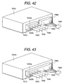
- Fig. 42 and Fig. 43 are the construction views for showing the connection manner of the module with the power bus 12.
- the construction is constituted by a module 4000 shown in Fig. 42, power buses 7020, 7030, 7040 and 7050 and an electric power line 7020a, a short sensor 7020b. Only the power buses are connected to the module 700 according to a connector 7010, another electric power line 7060 is connected to the module 7000 with another connector 7080. In the construction shown in Fig. 43, the power buses 7020, 7030, 7040 and 7050 and the another electric power line 7060 are connected to a module 7100 with the same connector 7110.
- the occupation area of the connector can be deleted, accordingly the module can be made small.
- Fig. 44 is the construction view in which the shunt resistor used in the over-current detection circuit is installed in the connector of the module.
- the construction is constituted by a connector housing 8040 of the module is connector terminals 8000 and 8010, a shunt resistor 8030, and the connector housing 8040 and the shunt resistor 8030 are connected to the connector terminals 8000 and 8010 according to the welding manner or the soldering manner.
- the construction is constituted by an electric power line 7020a of the power bus, a short sensor 7020b, and the electric power line 7020a and the short sensor 7020b are connected respectively to module side terminals 8010 and 8050 through terminals 8070 and 8080.
- the shunt resistor 8030a and the connection terminal 8000 are formed as one body 8030b.
- the shunt resistor is installed in the interior portion, the distance for flowing the large current can be shortened, further also the size of the module can be made small.
- the fuse number can be made small, further the wire harness for supplying the power supply can be shortened or can be lessened.
- the consumption current of the power supplying apparatus during the non-operation of the vehicle can be reduced.
Landscapes
- Engineering & Computer Science (AREA)
- Mechanical Engineering (AREA)
- Charge And Discharge Circuits For Batteries Or The Like (AREA)
- Emergency Protection Circuit Devices (AREA)
Applications Claiming Priority (2)
| Application Number | Priority Date | Filing Date | Title |
|---|---|---|---|
| JP18854998A JP3658503B2 (ja) | 1998-07-03 | 1998-07-03 | 乗物の電力供給装置及び集約配線装置 |
| JP18854998 | 1998-07-03 |
Publications (1)
| Publication Number | Publication Date |
|---|---|
| EP0968884A2 true EP0968884A2 (fr) | 2000-01-05 |
Family
ID=16225652
Family Applications (1)
| Application Number | Title | Priority Date | Filing Date |
|---|---|---|---|
| EP99112796A Withdrawn EP0968884A2 (fr) | 1998-07-03 | 1999-07-02 | Alimentation en puissance pour véhicule et câblage |
Country Status (3)
| Country | Link |
|---|---|
| US (2) | US6791207B2 (fr) |
| EP (1) | EP0968884A2 (fr) |
| JP (1) | JP3658503B2 (fr) |
Cited By (10)
| Publication number | Priority date | Publication date | Assignee | Title |
|---|---|---|---|---|
| WO2004048156A1 (fr) * | 2002-11-28 | 2004-06-10 | Daimlerchrysler Ag | Dispositif pour reactiver un appareil de commande |
| FR2919550A1 (fr) * | 2007-08-01 | 2009-02-06 | Faurecia Bloc Avant | Sous-ensemble electrique de vehicule automobile, vehicule et procede associes. |
| EP1764295A3 (fr) * | 2005-09-15 | 2009-02-18 | Kawasaki Jukogyo Kabushiki Kaisha | Véhicule de loisir |
| CN102616190A (zh) * | 2011-12-19 | 2012-08-01 | 埃泰克汽车电子(芜湖)有限公司 | 一种车身控制器保护电路 |
| WO2012077304A3 (fr) * | 2010-12-09 | 2012-08-23 | Yazaki Corporation | Dispositif de distribution de courant électrique pour véhicule |
| CN110247349A (zh) * | 2018-03-07 | 2019-09-17 | 矢崎总业株式会社 | 车用的电路体 |
| WO2022122642A1 (fr) * | 2020-12-09 | 2022-06-16 | Robert Bosch Gmbh | Véhicule présentant une architecture en zones |
| WO2022122643A1 (fr) * | 2020-12-09 | 2022-06-16 | Robert Bosch Gmbh | Véhicule à architecture de zones |
| WO2022122634A1 (fr) * | 2020-12-09 | 2022-06-16 | Robert Bosch Gmbh | Véhicule présentant une architecture en zones |
| WO2022122632A1 (fr) * | 2020-12-09 | 2022-06-16 | Robert Bosch Gmbh | Véhicule à architecture de zone |
Families Citing this family (55)
| Publication number | Priority date | Publication date | Assignee | Title |
|---|---|---|---|---|
| JP4253110B2 (ja) * | 2000-09-04 | 2009-04-08 | 株式会社日立製作所 | 車両制御システム |
| EP1346880B1 (fr) * | 2000-10-06 | 2018-12-26 | Xanavi Informatics Corporation | Dispositif d'information monte sur un vehicule |
| DE10105457A1 (de) * | 2001-02-07 | 2002-08-08 | Daimler Chrysler Ag | Vorrichtung zum Trennen und Schalten einer Last |
| JP2003046453A (ja) * | 2001-07-31 | 2003-02-14 | Denso Corp | 電源ic |
| DE10248456A1 (de) * | 2001-10-19 | 2003-06-18 | Denso Corp | Fahrzeugkommunikationssystem |
| US20030193308A1 (en) * | 2002-04-16 | 2003-10-16 | Richardson Gordon D. | Apparatus and method for testing a motor-shorting relay |
| US20040161960A1 (en) * | 2002-11-21 | 2004-08-19 | Autonetworks Technologies, Ltd. | Vehicle-installed relay box |
| US7999408B2 (en) * | 2003-05-16 | 2011-08-16 | Continental Automotive Systems, Inc. | Power and communication architecture for a vehicle |
| DE112004002301T5 (de) * | 2003-11-26 | 2006-09-28 | Littelfuse, Inc., Des Plaines | Elektrische Schutzeinrichtung für ein Fahrzeug und System, das diese einsetzt |
| US20050135034A1 (en) * | 2003-12-19 | 2005-06-23 | Caterpillar, Inc. | Resettable circuit breaker |
| JP4400340B2 (ja) * | 2004-06-30 | 2010-01-20 | 株式会社デンソー | 乗員保護システム |
| JP2006096095A (ja) * | 2004-09-28 | 2006-04-13 | Fuji Heavy Ind Ltd | 車載機器制御装置 |
| FR2878799B1 (fr) * | 2004-12-02 | 2008-07-18 | Renault Sas | Dispositif et procede de commande d'un vehicule |
| US20070084484A1 (en) * | 2005-10-17 | 2007-04-19 | Porter Eugene B | Selectively controllable heated wash system |
| JP2007123079A (ja) * | 2005-10-28 | 2007-05-17 | Honda Motor Co Ltd | 電動車両用蓄電器の冷却装置 |
| US20070120494A1 (en) * | 2005-11-29 | 2007-05-31 | Lahr Jeremy A | Vehicle daytime running light control system |
| JP4305875B2 (ja) * | 2006-05-22 | 2009-07-29 | 富士通テン株式会社 | 電源制御回路及び電源制御回路を備えた電子制御装置 |
| US20080004766A1 (en) * | 2006-06-23 | 2008-01-03 | Gallo Michele R A | Control system for automobiles |
| JP4365847B2 (ja) * | 2006-10-24 | 2009-11-18 | 三菱電機株式会社 | 車載電気負荷の給電制御装置 |
| JP4930835B2 (ja) * | 2007-02-21 | 2012-05-16 | スズキ株式会社 | エンジン始動制御装置 |
| US9434261B2 (en) * | 2011-10-17 | 2016-09-06 | Robert Bosch Gmbh | Welded contactor checking systems and methods |
| KR101535825B1 (ko) * | 2012-09-25 | 2015-07-10 | 엘지디스플레이 주식회사 | 표시장치 및 이의 라인결함 검출방법 |
| CN105246766B (zh) * | 2014-01-08 | 2017-04-05 | 日本精工株式会社 | 电动助力转向装置 |
| JP6252191B2 (ja) * | 2014-01-17 | 2017-12-27 | マツダ株式会社 | 車両の電源供給システム |
| US10033213B2 (en) | 2014-09-30 | 2018-07-24 | Johnson Controls Technology Company | Short circuit wake-up system and method for automotive battery while in key-off position |
| JP2016120901A (ja) * | 2014-12-24 | 2016-07-07 | 株式会社オートネットワーク技術研究所 | 自動車用電源供給装置 |
| DE112017003155B4 (de) | 2016-06-24 | 2023-01-19 | Yazaki Corporation | Stromkreiskörper für fahrzeug |
| JP6889716B2 (ja) * | 2016-06-24 | 2021-06-18 | 矢崎総業株式会社 | 車両用回路体 |
| WO2017222074A1 (fr) | 2016-06-24 | 2017-12-28 | 矢崎総業株式会社 | Structure de circuit de véhicule |
| WO2017222076A1 (fr) * | 2016-06-24 | 2017-12-28 | 矢崎総業株式会社 | Corps de circuit pour véhicule |
| WO2017222073A1 (fr) | 2016-06-24 | 2017-12-28 | 矢崎総業株式会社 | Structure de circuit de véhicule |
| US10168372B2 (en) * | 2016-12-14 | 2019-01-01 | General Electric Company | System and method for leakage current and fault location detection in electric vehicle DC power circuits |
| CN107121976A (zh) * | 2017-05-03 | 2017-09-01 | 北京新能源汽车股份有限公司 | 一种电机控制器的检测装置及其故障检测方法和电动汽车 |
| JP6555668B2 (ja) * | 2017-07-13 | 2019-08-07 | 本田技研工業株式会社 | 車両制御システム |
| JP7107669B2 (ja) * | 2017-12-04 | 2022-07-27 | 矢崎総業株式会社 | 車載制御システム及びワイヤハーネス |
| JP7025188B2 (ja) * | 2017-12-04 | 2022-02-24 | 矢崎総業株式会社 | 車両用の回路体、及び、車両用の回路体の製造方法 |
| JP7123551B2 (ja) * | 2017-12-04 | 2022-08-23 | 矢崎総業株式会社 | 車両用の回路体 |
| JP7040963B2 (ja) * | 2018-03-07 | 2022-03-23 | 矢崎総業株式会社 | ワイヤハーネスの製造方法、及び、ワイヤハーネス |
| CN108983000B (zh) * | 2018-07-27 | 2021-11-23 | 北京新能源汽车股份有限公司 | 一种高压互锁检测电路、高压互锁检测系统和汽车 |
| JP7124618B2 (ja) * | 2018-10-03 | 2022-08-24 | 株式会社オートネットワーク技術研究所 | 自動車用配線システム |
| WO2020076861A2 (fr) * | 2018-10-09 | 2020-04-16 | Uncharted Power, Inc. | Systèmes et procédés modulaires pour la surveillance et la distribution d'énergie |
| DE102018127045A1 (de) * | 2018-10-30 | 2020-04-30 | Infineon Technologies Ag | Kontaktelement, leistungshalbleitermodul mit einem kontaktelement und verfahren zum herstellen eines kontaktelementes |
| JP2020082851A (ja) * | 2018-11-19 | 2020-06-04 | トヨタ自動車株式会社 | 車両の電源幹線配索構造 |
| JP7408944B2 (ja) * | 2019-07-30 | 2024-01-09 | マツダ株式会社 | 車載電源システム |
| KR102242061B1 (ko) * | 2020-02-06 | 2021-04-20 | 주식회사 경신 | 자율주행 차량의 전원 제어 장치 |
| US11262408B2 (en) * | 2020-02-24 | 2022-03-01 | Ford Global Technologies, Llc | Vehicle traction battery over-discharge diagnosing method and assembly |
| EP4110643A1 (fr) | 2020-02-27 | 2023-01-04 | CNH Industrial Italia S.P.A. | Véhicule de travail électrique ayant une chaîne cinématique électrique et une configuration de composant de stockage |
| JP2021136191A (ja) * | 2020-02-28 | 2021-09-13 | 株式会社デンソーエレクトロニクス | 電源供給回路 |
| DE102020129130B3 (de) * | 2020-11-05 | 2022-01-27 | Dr. Ing. H.C. F. Porsche Aktiengesellschaft | Verfahren und System zu einem Sicherheitskonzept einer Wechselstrombatterie |
| CN113353093B (zh) * | 2021-08-10 | 2021-12-10 | 北汽福田汽车股份有限公司 | 车辆的控制方法、装置和车辆 |
| DE102021130880A1 (de) * | 2021-11-25 | 2023-05-25 | Zf Cv Systems Europe Bv | System mit mehreren Ansteuermodulen sowie Ansteuermodul für mindestens einen Aktor eines Rades oder einer Achse eines Fahrzeugs und Fahrzeug damit sowie Verfahren |
| CN115810811B (zh) * | 2022-01-07 | 2023-08-18 | 宁德时代新能源科技股份有限公司 | 电池包主动熔断器控制装置 |
| CN114734941A (zh) * | 2022-04-18 | 2022-07-12 | 重庆长安汽车股份有限公司 | 一种匹配不同线径的车身控制系统及方法 |
| US12135591B2 (en) * | 2022-07-06 | 2024-11-05 | Gm Cruise Holdings Llc | Environmental and electromagnetic seal for autonomous vehicle control systems |
| CN116505507B (zh) * | 2023-04-28 | 2025-03-21 | 中航锂电(洛阳)有限公司 | 控制电路、供电系统、负载系统、电能系统及电动车 |
Family Cites Families (6)
| Publication number | Priority date | Publication date | Assignee | Title |
|---|---|---|---|---|
| US5432495A (en) * | 1990-01-29 | 1995-07-11 | Tompkins; Eugene | Beeper controlled auto security system |
| WO1996026570A1 (fr) | 1995-02-21 | 1996-08-29 | Hitachi, Ltd. | Appareil et procede de fourniture d'electricite a un vehicule, dispositif a circuits semiconducteurs a utiliser dans ledit appareil et dispositif de cablage commun pour une automobile ou un autre vehicule |
| US5808371A (en) * | 1995-09-05 | 1998-09-15 | Hitachi, Ltd. | Apparatus for driving electrical loads provided at a vehicle |
| JPH09275632A (ja) * | 1996-04-04 | 1997-10-21 | Harness Sogo Gijutsu Kenkyusho:Kk | 電力分配システム |
| US6163082A (en) * | 1996-06-13 | 2000-12-19 | Hitachi, Ltd. | Power supplying apparatus for a vehicle and an intensive wiring apparatus |
| JP3374361B2 (ja) * | 1997-04-04 | 2003-02-04 | 矢崎総業株式会社 | 車両の異常電流検出方法及び車両の異常電流検出装置並びに車両用電源供給装置 |
-
1998
- 1998-07-03 JP JP18854998A patent/JP3658503B2/ja not_active Expired - Fee Related
-
1999
- 1999-07-02 EP EP99112796A patent/EP0968884A2/fr not_active Withdrawn
- 1999-07-02 US US09/349,211 patent/US6791207B2/en not_active Expired - Fee Related
-
2004
- 2004-07-15 US US10/891,044 patent/US7282810B2/en not_active Expired - Fee Related
Non-Patent Citations (1)
| Title |
|---|
| None |
Cited By (15)
| Publication number | Priority date | Publication date | Assignee | Title |
|---|---|---|---|---|
| WO2004048156A1 (fr) * | 2002-11-28 | 2004-06-10 | Daimlerchrysler Ag | Dispositif pour reactiver un appareil de commande |
| EP1764295A3 (fr) * | 2005-09-15 | 2009-02-18 | Kawasaki Jukogyo Kabushiki Kaisha | Véhicule de loisir |
| US7680564B2 (en) | 2005-09-15 | 2010-03-16 | Kawasaki Jukogyo Kabushiki Kaisha | Leisure vehicle |
| FR2919550A1 (fr) * | 2007-08-01 | 2009-02-06 | Faurecia Bloc Avant | Sous-ensemble electrique de vehicule automobile, vehicule et procede associes. |
| EP2022695A1 (fr) * | 2007-08-01 | 2009-02-11 | Faurecia Bloc Avant | Sous-ensemble électrique de véhicule automobile, véhicule et procédé associés |
| WO2012077304A3 (fr) * | 2010-12-09 | 2012-08-23 | Yazaki Corporation | Dispositif de distribution de courant électrique pour véhicule |
| CN103260958A (zh) * | 2010-12-09 | 2013-08-21 | 矢崎总业株式会社 | 车辆电力分配装置 |
| CN103260958B (zh) * | 2010-12-09 | 2015-11-25 | 矢崎总业株式会社 | 车辆电力分配装置 |
| US9377831B2 (en) | 2010-12-09 | 2016-06-28 | Yazaki Corporation | Vehicle electric power distribution device |
| CN102616190A (zh) * | 2011-12-19 | 2012-08-01 | 埃泰克汽车电子(芜湖)有限公司 | 一种车身控制器保护电路 |
| CN110247349A (zh) * | 2018-03-07 | 2019-09-17 | 矢崎总业株式会社 | 车用的电路体 |
| WO2022122642A1 (fr) * | 2020-12-09 | 2022-06-16 | Robert Bosch Gmbh | Véhicule présentant une architecture en zones |
| WO2022122643A1 (fr) * | 2020-12-09 | 2022-06-16 | Robert Bosch Gmbh | Véhicule à architecture de zones |
| WO2022122634A1 (fr) * | 2020-12-09 | 2022-06-16 | Robert Bosch Gmbh | Véhicule présentant une architecture en zones |
| WO2022122632A1 (fr) * | 2020-12-09 | 2022-06-16 | Robert Bosch Gmbh | Véhicule à architecture de zone |
Also Published As
| Publication number | Publication date |
|---|---|
| US20040257732A1 (en) | 2004-12-23 |
| US6791207B2 (en) | 2004-09-14 |
| US20030075980A1 (en) | 2003-04-24 |
| JP3658503B2 (ja) | 2005-06-08 |
| US7282810B2 (en) | 2007-10-16 |
| JP2000016201A (ja) | 2000-01-18 |
Similar Documents
| Publication | Publication Date | Title |
|---|---|---|
| EP0968884A2 (fr) | Alimentation en puissance pour véhicule et câblage | |
| US6294845B1 (en) | Power supplying apparatus for a vehicle and an intensive wiring apparatus | |
| US7932623B2 (en) | Method and system for driving a vehicle trailer tow connector | |
| US6401891B1 (en) | Device and method for supplying power to a vehicle, semi-conductor circuit device for use in the same and collective wiring devices for a vehicle or an automobile | |
| JP3872814B2 (ja) | 自動車内に配設可能な機能モジュール用の回路装置 | |
| US6205010B1 (en) | Switch circuit having protection function to interrupt input of control signal | |
| US20090015976A1 (en) | Power feed system for vehicle | |
| US6163082A (en) | Power supplying apparatus for a vehicle and an intensive wiring apparatus | |
| JP3552597B2 (ja) | 乗物の電力供給装置及び集約配線装置 | |
| KR19990083726A (ko) | 자동차전기장치의디지털통합제어장치및방법 | |
| JPWO1996026570A1 (ja) | 乗物の電力供給装置及びその方法、それに用いる半導体回路装置及び乗物あるいは自動車の集約配線装置 | |
| WO2012006279A1 (fr) | Système électrique et électronique possédant un centre électrique pour véhicule | |
| JPH10341524A (ja) | 車載用信号伝送装置と信号伝送方法及び車載用電力供給制御装置と電力制御方法及び車載ケーブル異常検出装置 | |
| JP2004352249A (ja) | 乗物の電力供給装置及び集約配線装置 | |
| CN1717349A (zh) | 机动车辆的板载电源系统 | |
| JP3468697B2 (ja) | 車両用電力供給装置 | |
| JP7492586B2 (ja) | 車載用電子制御装置及び車載機器制御方法 | |
| JPH1084629A (ja) | 電力分配システム | |
| JP2000194403A (ja) | 車両用負荷診断装置 | |
| JPH1020970A (ja) | 集約配線装置 | |
| JP2001315593A (ja) | 乗物内の電力供給装置及び方法,乗物の集約配線装置,半導体回路 | |
| JP3734918B2 (ja) | 車両用電源分配装置 | |
| JP2006131222A (ja) | 自動車の集約配線装置 | |
| JPS639870A (ja) | 自動車の電気ユニットの電力供給および点検装置 | |
| JP2000177511A (ja) | 乗物の電源供給装置及び集約配線装置 |
Legal Events
| Date | Code | Title | Description |
|---|---|---|---|
| PUAI | Public reference made under article 153(3) epc to a published international application that has entered the european phase |
Free format text: ORIGINAL CODE: 0009012 |
|
| AK | Designated contracting states |
Kind code of ref document: A2 Designated state(s): AT BE CH CY DE DK ES FI FR GB GR IE IT LI LU MC NL PT SE |
|
| AX | Request for extension of the european patent |
Free format text: AL;LT;LV;MK;RO;SI |
|
| STAA | Information on the status of an ep patent application or granted ep patent |
Free format text: STATUS: THE APPLICATION IS DEEMED TO BE WITHDRAWN |
|
| 18D | Application deemed to be withdrawn |
Effective date: 20090203 |