WO2017222076A1 - Corps de circuit pour véhicule - Google Patents
Corps de circuit pour véhicule Download PDFInfo
- Publication number
- WO2017222076A1 WO2017222076A1 PCT/JP2017/023315 JP2017023315W WO2017222076A1 WO 2017222076 A1 WO2017222076 A1 WO 2017222076A1 JP 2017023315 W JP2017023315 W JP 2017023315W WO 2017222076 A1 WO2017222076 A1 WO 2017222076A1
- Authority
- WO
- WIPO (PCT)
- Prior art keywords
- line
- vehicle
- control unit
- backbone
- power
- Prior art date
- Legal status (The legal status is an assumption and is not a legal conclusion. Google has not performed a legal analysis and makes no representation as to the accuracy of the status listed.)
- Ceased
Links
Images



Classifications
-
- B—PERFORMING OPERATIONS; TRANSPORTING
- B60—VEHICLES IN GENERAL
- B60R—VEHICLES, VEHICLE FITTINGS, OR VEHICLE PARTS, NOT OTHERWISE PROVIDED FOR
- B60R16/00—Electric or fluid circuits specially adapted for vehicles and not otherwise provided for; Arrangement of elements of electric or fluid circuits specially adapted for vehicles and not otherwise provided for
- B60R16/02—Electric or fluid circuits specially adapted for vehicles and not otherwise provided for; Arrangement of elements of electric or fluid circuits specially adapted for vehicles and not otherwise provided for electric constitutive elements
- B60R16/023—Electric or fluid circuits specially adapted for vehicles and not otherwise provided for; Arrangement of elements of electric or fluid circuits specially adapted for vehicles and not otherwise provided for electric constitutive elements for transmission of signals between vehicle parts or subsystems
- B60R16/0238—Electrical distribution centers
-
- B—PERFORMING OPERATIONS; TRANSPORTING
- B60—VEHICLES IN GENERAL
- B60R—VEHICLES, VEHICLE FITTINGS, OR VEHICLE PARTS, NOT OTHERWISE PROVIDED FOR
- B60R16/00—Electric or fluid circuits specially adapted for vehicles and not otherwise provided for; Arrangement of elements of electric or fluid circuits specially adapted for vehicles and not otherwise provided for
- B60R16/02—Electric or fluid circuits specially adapted for vehicles and not otherwise provided for; Arrangement of elements of electric or fluid circuits specially adapted for vehicles and not otherwise provided for electric constitutive elements
- B60R16/03—Electric or fluid circuits specially adapted for vehicles and not otherwise provided for; Arrangement of elements of electric or fluid circuits specially adapted for vehicles and not otherwise provided for electric constitutive elements for supply of electrical power to vehicle subsystems or for
-
- B—PERFORMING OPERATIONS; TRANSPORTING
- B60—VEHICLES IN GENERAL
- B60K—ARRANGEMENT OR MOUNTING OF PROPULSION UNITS OR OF TRANSMISSIONS IN VEHICLES; ARRANGEMENT OR MOUNTING OF PLURAL DIVERSE PRIME-MOVERS IN VEHICLES; AUXILIARY DRIVES FOR VEHICLES; INSTRUMENTATION OR DASHBOARDS FOR VEHICLES; ARRANGEMENTS IN CONNECTION WITH COOLING, AIR INTAKE, GAS EXHAUST OR FUEL SUPPLY OF PROPULSION UNITS IN VEHICLES
- B60K37/00—Dashboards
- B60K37/20—Dashboard panels
-
- B—PERFORMING OPERATIONS; TRANSPORTING
- B60—VEHICLES IN GENERAL
- B60L—PROPULSION OF ELECTRICALLY-PROPELLED VEHICLES; SUPPLYING ELECTRIC POWER FOR AUXILIARY EQUIPMENT OF ELECTRICALLY-PROPELLED VEHICLES; ELECTRODYNAMIC BRAKE SYSTEMS FOR VEHICLES IN GENERAL; MAGNETIC SUSPENSION OR LEVITATION FOR VEHICLES; MONITORING OPERATING VARIABLES OF ELECTRICALLY-PROPELLED VEHICLES; ELECTRIC SAFETY DEVICES FOR ELECTRICALLY-PROPELLED VEHICLES
- B60L1/00—Supplying electric power to auxiliary equipment of vehicles
-
- B—PERFORMING OPERATIONS; TRANSPORTING
- B60—VEHICLES IN GENERAL
- B60R—VEHICLES, VEHICLE FITTINGS, OR VEHICLE PARTS, NOT OTHERWISE PROVIDED FOR
- B60R16/00—Electric or fluid circuits specially adapted for vehicles and not otherwise provided for; Arrangement of elements of electric or fluid circuits specially adapted for vehicles and not otherwise provided for
- B60R16/02—Electric or fluid circuits specially adapted for vehicles and not otherwise provided for; Arrangement of elements of electric or fluid circuits specially adapted for vehicles and not otherwise provided for electric constitutive elements
-
- B—PERFORMING OPERATIONS; TRANSPORTING
- B60—VEHICLES IN GENERAL
- B60R—VEHICLES, VEHICLE FITTINGS, OR VEHICLE PARTS, NOT OTHERWISE PROVIDED FOR
- B60R16/00—Electric or fluid circuits specially adapted for vehicles and not otherwise provided for; Arrangement of elements of electric or fluid circuits specially adapted for vehicles and not otherwise provided for
- B60R16/02—Electric or fluid circuits specially adapted for vehicles and not otherwise provided for; Arrangement of elements of electric or fluid circuits specially adapted for vehicles and not otherwise provided for electric constitutive elements
- B60R16/0207—Wire harnesses
-
- B—PERFORMING OPERATIONS; TRANSPORTING
- B60—VEHICLES IN GENERAL
- B60R—VEHICLES, VEHICLE FITTINGS, OR VEHICLE PARTS, NOT OTHERWISE PROVIDED FOR
- B60R16/00—Electric or fluid circuits specially adapted for vehicles and not otherwise provided for; Arrangement of elements of electric or fluid circuits specially adapted for vehicles and not otherwise provided for
- B60R16/02—Electric or fluid circuits specially adapted for vehicles and not otherwise provided for; Arrangement of elements of electric or fluid circuits specially adapted for vehicles and not otherwise provided for electric constitutive elements
- B60R16/0207—Wire harnesses
- B60R16/0215—Protecting, fastening and routing means therefor
-
- H—ELECTRICITY
- H01—ELECTRIC ELEMENTS
- H01B—CABLES; CONDUCTORS; INSULATORS; SELECTION OF MATERIALS FOR THEIR CONDUCTIVE, INSULATING OR DIELECTRIC PROPERTIES
- H01B7/00—Insulated conductors or cables characterised by their form
- H01B7/0045—Cable-harnesses
-
- B—PERFORMING OPERATIONS; TRANSPORTING
- B60—VEHICLES IN GENERAL
- B60K—ARRANGEMENT OR MOUNTING OF PROPULSION UNITS OR OF TRANSMISSIONS IN VEHICLES; ARRANGEMENT OR MOUNTING OF PLURAL DIVERSE PRIME-MOVERS IN VEHICLES; AUXILIARY DRIVES FOR VEHICLES; INSTRUMENTATION OR DASHBOARDS FOR VEHICLES; ARRANGEMENTS IN CONNECTION WITH COOLING, AIR INTAKE, GAS EXHAUST OR FUEL SUPPLY OF PROPULSION UNITS IN VEHICLES
- B60K35/00—Instruments specially adapted for vehicles; Arrangement of instruments in or on vehicles
- B60K35/20—Output arrangements, i.e. from vehicle to user, associated with vehicle functions or specially adapted therefor
-
- H—ELECTRICITY
- H01—ELECTRIC ELEMENTS
- H01B—CABLES; CONDUCTORS; INSULATORS; SELECTION OF MATERIALS FOR THEIR CONDUCTIVE, INSULATING OR DIELECTRIC PROPERTIES
- H01B7/00—Insulated conductors or cables characterised by their form
Definitions
- the present invention relates to a vehicle circuit body arranged in a vehicle.
- a wire harness which is an assembly of a number of electric wires, is routed on the vehicle, and power is supplied by connecting the main power supply and the electrical components of each part via the wire harness.
- junction blocks are used to distribute power to multiple systems
- relay boxes are used to control power supply on / off for each system
- fuse boxes are used to protect each wire and load of the wire harness. Is generally used.
- the wire harness shown in Patent Document 1 includes a network transmission path and a circuit for supplying power, GND, and other signals.
- the wire harness includes a wire harness main line, a sub-wire harness, an optional sub-wire harness, and a network hub device.
- the present invention has been made in view of the above-described circumstances, and its purpose is to provide a structure for electrical connection between various electrical components and a power source on a vehicle and between electrical components, particularly a configuration of a main line portion.
- An object of the present invention is to provide a vehicle circuit body that can be simplified and can easily add a new electric wire.
- a vehicle circuit body is characterized by the following (1) to (7).
- a vehicle circuit body installed in a vehicle A plurality of control units; A trunk line connecting the plurality of control units to each other; A branch line directly or indirectly connecting the control unit and the auxiliary machine; With The trunk line has a power line and a communication line,
- the control unit includes a main line connection unit to which the main line is connected, and a branch line connection unit to which the branch line is connected. Circuit body for vehicles.
- the plurality of control units are A first control unit; A second control unit that is spaced apart from the first control unit in the front or rear direction of the vehicle, and
- the trunk line is constituted by a first trunk line that connects the first control unit and the second control unit,
- the vehicle circuit body according to (1) above.
- the plurality of control units further, a third control unit arranged to be separated from the first control unit in the vehicle width direction of the vehicle, A fourth control unit arranged in the vehicle width direction with respect to the first control unit and spaced apart at a position opposite to the third control unit;
- the trunk line further includes a second trunk line connecting the first control unit and the third control unit, A third trunk line connecting the first control unit and the fourth control unit; Having The vehicle circuit body according to (2) above.
- the vehicle has a first region including a passenger compartment, and a second region different from the first region,
- the plurality of control units are provided in the first region,
- One of the plurality of control units has a power input terminal to which power is supplied from a power source, and the control unit supplies power input from the power input terminal to the main line.
- the vehicle circuit body according to any one of (1) to (3) above.
- the power supply line includes a first power supply line and a second power supply line used as a backup for the first power supply line.
- the vehicle circuit body according to any one of (1) to (4).
- Each of the first power line and the second power line is made of a strip-shaped metal material having a flat cross-sectional shape
- the trunk line has a structure in which the metal materials of the first power supply line and the second power supply line are stacked in the thickness direction via an insulator.
- the trunk line further includes an earth line.
- the vehicle circuit body according to any one of (1) to (6) above.
- the vehicle circuit body having the configuration of (1) above it is possible to provide a vehicle circuit body that can simplify the configuration of the trunk portion and facilitate the addition of new electric wires.
- the first and second control units are arranged in the vehicle front-rear direction, so that by using the trunk line connecting these control units, the vehicle Power supply and transmission / reception of communication data are facilitated.
- the third to fourth control units are arranged in the vehicle width direction, and therefore, for example, branch lines to auxiliary devices installed on the side of the vehicle Deployment becomes easier.
- the power of the power source is supplied to the main line via the power input terminal and the control unit. Therefore, even when the shape and structure of the power cable connected to the power input terminal and the trunk line are different, power can be supplied. This eliminates the need for, for example, a specially shaped trunk line to pass through the dash panel of the vehicle body, and facilitates the work of routing the portion that passes through the dash panel.
- the power supply backup is performed using the second power supply line. It is possible to secure a route for performing.
- the vehicle circuit body configured as described in (6) above, since a plurality of strip-shaped metal materials are laminated, the cross-sectional area of the trunk line is increased in order to allow passage of a large power supply current. However, the bending in the thickness direction is relatively easy, and the work for routing along a desired routing path on the vehicle body is facilitated.
- the power supply current and communication can be transmitted between the control units, and a common ground can also be formed.
- a common ground can also be formed.
- the structure for electrical connection between various electrical components and a power source on the vehicle and between electrical components, particularly the configuration of the trunk portion is simplified, and a new electric wire is added. Will also be easier.
- FIG. 1 is a perspective view illustrating a configuration example of a main part of an in-vehicle apparatus including a vehicle circuit body according to an embodiment of the present invention.
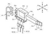
- FIG. 2 is a perspective view showing a configuration in the vicinity of one backbone control box 31, 32, 33 shown in FIG. 3A, 3B, 3C, and 3D are a plan view, a front view, a bottom view, and a right side view showing the backbone control box 31, respectively.
- FIG. 4 is a front view showing the configuration of the backbone control box and the vicinity thereof.
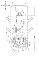
- FIG. 5 is a plan view illustrating a configuration example of a main part of the in-vehicle device including the vehicle circuit body illustrated in FIG. 1.
- FIG. 1 shows a configuration example of main parts of an in-vehicle device including a vehicle circuit body according to an embodiment of the present invention. Further, components in the vicinity of one backbone control box 31 shown in FIG. 1 are extracted and shown in FIG. In addition, a plan view, a front view, a bottom view, and a right side view of the backbone control box 31 are shown in FIGS. 3 (a), 3 (b), 3 (c), and 3 (d), respectively.
- the vehicle circuit body shown in FIG. 1 supplies power from a main power source such as an in-vehicle battery to auxiliary devices in various parts of the vehicle body, that is, various electrical components, and exchanges signals between electrical components. Therefore, it is used as a necessary transmission line. That is, it is functionally the same as a general wire harness, but the structure is significantly different from a general wire harness.
- a main power source such as an in-vehicle battery
- auxiliary devices in various parts of the vehicle body that is, various electrical components, and exchanges signals between electrical components. Therefore, it is used as a necessary transmission line. That is, it is functionally the same as a general wire harness, but the structure is significantly different from a general wire harness.
- the on-vehicle apparatus shown in FIG. 1 represents the configuration on the vehicle interior side in the vicinity of the dash panel 16 that partitions the engine room 11 and the vehicle compartment (passenger compartment) 13 of the vehicle body.
- a lean hose (not shown), which is a reinforcing material, is directed toward the left and right direction (vehicle width direction) of the vehicle body at an instrument panel portion (instrument panel portion) slightly behind the dash panel 16. It is installed to extend.
- a part of the components of the vehicle circuit body is disposed in the vicinity of the lean hose.
- the vehicle circuit body in a portion extending in the left-right direction of the vehicle body may be fixed to the lean hose, fixed to the dash panel 16, or fixed to a dedicated fixture.
- the vehicle circuit body shown in FIG. 1 includes a plurality of backbone trunk portions 21, 22, and 23 and a plurality of backbone control boxes 31, 32, and 33.
- Each of the backbone trunk lines 21, 22, and 23 includes lines such as a power supply line, an earth line, and a communication line.
- a band-shaped metal material for example, copper or aluminum
- these metal materials are electrically insulated from each other in the thickness direction. It is constructed by stacking. Thereby, passage of a large current can be permitted, and bending in the thickness direction is relatively easy.
- the backbone trunk portions 21 and 22 are linearly arranged in the left-right direction at positions along the surface of the dash panel 16 so as to be substantially parallel to the lean hose at a position above the lean hose. Further, the backbone trunk portion 23 is disposed at a substantially central portion in the left-right direction of the vehicle body, and linearly extends in the vertical direction at a location along the surface of the dash panel 16. Further, the backbone trunk portion 23 is bent in the thickness direction by approximately 90 degrees in the vicinity of the boundary between the dash panel 16 and the vehicle interior floor, and is disposed so as to extend in the front-rear direction of the vehicle body along the vehicle interior floor.
- the backbone trunk lines 21 and 22 may be fixed to the lean hose.
- the backbone control box 32 (first control unit) is disposed at a substantially central portion in the left-right direction of the vehicle body, and the backbone control box 31 (second control unit) is disposed near the left end in the left-right direction, and the backbone control box 33 ( The third control unit is disposed near the right end in the left-right direction.
- the left end of the backbone trunk section 21 (first trunk line) is connected to the right end of the backbone control box 31, and the right end of the backbone trunk section 21 is connected to the left end of the backbone control box 32.
- the left end of the backbone trunk section 22 (second trunk line) is connected to the right end of the backbone control box 32, and the right end of the backbone trunk section 22 is connected to the left end of the backbone control box 33.
- the front end of the backbone trunk portion 23 (third trunk line) is connected to the lower end of the backbone control box 32.
- the backbone trunk lines 21 to 23 and the backbone control boxes 31 to 33 are formed in a shape similar to a T-shape as shown in FIG. Further, the internal circuits of the backbone trunk lines 21 to 23 are in a state where they can be electrically connected to each other via the backbone control box 32.
- the backbone control box 31 disposed on the left side of the vehicle body is provided with a main power supply connection part 31a, a main line connection part 31b, and a branch line connection part 31c.
- the main power cable 41 is connected to the main power connection part 31a of the backbone control box 31
- the left end of the backbone trunk part 21 is connected to the main line connection part 31b
- the branch line connection part 31c is connected to the branch line connection part 31c.
- a plurality of branch line sub-harnesses 42 (1), 42 (2), and 42 (3) are connected to each other.
- the backbone trunk 21 includes power supply lines 21a and 21b, a ground line 21c, and a communication line 21d.
- the main power cable 41 includes a power line 41a and a ground line 41b.
- one power supply line 21a is used as a path for supplying power from the main power supply.
- the other power supply line 21b is used as a path for supplying backup power supply when an abnormality occurs.
- the backbone control box 31 includes a relay circuit 31d for connecting the power supply system, the ground system, and the communication system of each circuit among the main power cable 41, the backbone trunk line 21, and the branch line subharness 42. It is included.
- the relay circuit 31d includes a semiconductor switch having a fusible link or relay function. The fusible link cuts off the current when an excessive power supply current flows.
- the relay has a function of switching energization on and off as necessary for each system.
- the relay circuit 31d is configured by a circuit or a bus bar configured on a printed circuit board in the backbone control box 31.
- the backbone trunk 21 and the main power cable 41 are greatly different in shape and structure. However, by interposing the relay circuit 31d of the backbone control box 31, the circuit of the backbone trunk 21 and the main power cable are connected. 41 circuits can be easily connected.
- the terminals connected to the respective ends of the power line 41a and the earth line 41b are connected to the terminals of the main power connection part 31a, and these circuits are connected by fixing them with bolts and nuts. can do.
- the power supply lines 21a and 21b and the earth line 21c of the backbone trunk line 21 are connected to circuits on the printed circuit board in the backbone control box 31, respectively, and are fixed using, for example, bolts and nuts.
- the communication line 21d is connected to a circuit on a printed board in the backbone control box 31 using a connector. Also, the connection portions of the power supply lines 21a and 21b and the earth line 21c can be easily attached and detached by adopting connectors.
- the connectors provided at the respective tips are detachable from the branch line connection portion 31c, and a circuit can be connected as necessary.
- Each of the branch line sub-harnesses 42 (1) to 42 (3) is configured to include all or a part of the power supply line, the earth line, and the communication line.
- the branch line connecting portion 31c is provided with six connectors, a maximum of six branch line sub-harnesses 42 can be connected.
- the backbone trunk portions 21 to 23 and the backbone control boxes 31 to 33 are combined, and various branch line sub-harnesses 42 to 44 are connected to the backbone control boxes 31 to 33, whereby the backbone (backbone) is obtained.
- various transmission lines can be routed.
- branch sub-harnesses 42 to 44 can be handled by adding or changing the branch sub-harnesses 42 to 44 connected to any of the backbone control boxes 31 to 33. There is no need to change the structure of the main circuit body.
- the branch line sub-harnesses 42 to 44 are connected to the backbone control boxes 31 to 33.
- another branch point is provided at an appropriate relay point on the backbone trunks 21 to 23.
- a wire sub-harness (not shown) may be connected.
- an electronic control unit (ECU) 51 provided in the vehicle can be connected to the backbone control box 31 and other electrical components via a branch line sub-harness 42. it can. Further, the electronic control units 51, 52, 53 and other electrical components can be connected to the backbone control box 32 via the branch line sub-harness 43. Furthermore, various electrical components can be connected to the backbone control box 33 via the branch line sub-harness 44. Each electronic control unit 51, 52, 53 can control various electrical components on the vehicle via the communication lines of the branch sub-harnesses 42, 43, 44, the backbone control boxes 31 to 33, and the like. it can.
- the vehicle circuit body shown in FIG. 1 needs to be connected not only to the electrical components inside the passenger compartment 13 but also to the main power source and electrical components in the engine room 11.
- the dash panel needs to have the functions of insulating the vibration from the engine room, reducing the vibration and noise from the suspension, and blocking high heat, noise, odor, etc. In order not to impair the function, sufficient consideration is also required for the penetration portion of the electrical connection member.
- the backbone main line portions 21 to 23 and the backbone control boxes 31 to 33 which are the main components, are all arranged in the space on the passenger compartment 13 side.
- the problem of the location penetrating the panel 16 can be easily solved.
- the main power cable 41 connected to the left end of the backbone control box 31 is routed so as to pass through the through hole 16a of the dash panel 16, and the main power supply circuit in the engine room 11 is arranged. And the power supply circuit of the backbone control box 31 are connected via the main power cable 41. Thereby, the power of the main power source can be supplied to the backbone control box 31.
- the main power cable 41 can be made of a material that can be easily bent, can have a circular cross-sectional shape, or can be configured to have a relatively small cross-sectional area, it is easy to seal the through-hole 16a. It is possible to avoid deterioration of workability when carrying out the routing work.
- a part of the branch line sub-harness 42 connected to the backbone control box 31 penetrates the dash panel 16.
- a desired electrical connection path can be realized.
- the branch line sub-harnesses 42, 44 and the like have a small cross-sectional area and can be easily bent. Therefore, it is easy to seal a portion penetrating the dash panel 16.
- branch line sub-harness installed at the location penetrating the dash panel 16 can be limited to only the communication line.
- branch line sub-harness may be specially configured as a communication trunk line different from the branch line sub-harnesses 42 to 44 branched from the backbone trunk line.
- FIG. 4 shows the configuration of the backbone control box 32 and the vicinity thereof.
- the backbone control box 32 includes a main line connection part 32a provided on the left end side, a main line connection part 32b provided on the right end side, and a main line connection part 32c provided on the lower end side.
- the right end of the backbone main line part 21 can be connected to the main line connecting part 32a
- the left end of the backbone main line part 22 can be connected to the main line connecting part 32b
- the backbone main line part 23 can be connected to the main line connecting part 32c.
- the tip of can be connected.
- the connector CN11 provided at the main line connection portion 32a and the connector CN12 provided at the right end of the backbone main line portion 21 are configured to be detachable.
- a connector CN21 provided at the main line connection portion 32b and a connector CN22 provided at the left end of the backbone main line portion 22 are configured to be detachable.
- the connector CN31 provided at the main line connection portion 32c and the connector CN32 provided at the tip of the backbone main line portion 23 are configured to be detachable.
- two power lines (21a, 21b), a ground line (21c), and a communication line (21d) including two signal lines are provided in each of the backbone trunk lines 21, 22, and 23.
- two power supply lines 21a and 21b, a ground line 21c, and a communication line 21d of the backbone trunk section 21 are connected to each of the five terminals T12a to T12e arranged side by side in the connector CN12.
- Two signal lines are connected to each other.
- two signals of the power supply line, the ground line, and the communication line of the backbone trunk section 22 are connected to each of the five terminals T22a to T22e arranged side by side in the connector CN22.
- Each line is connected.
- two signal lines of two power lines, a ground line, and a communication line of the backbone trunk section 23 are connected to each of the five terminals T32a to T32e arranged side by side in the connector CN32. And are connected to each other.
- the connector CN11 of the backbone control box 32 five terminals T11a to T11e that can be engaged with each of the terminals T12a to T12e in the connector CN12 in a male / female relationship are arranged side by side at positions adjacent to each other.
- the connector CN21 five terminals T21a to T21e that can be engaged with each of the terminals T22a to T22e in the connector CN22 are arranged side by side at positions adjacent to each other.
- the connector CN31 five terminals T31a to T31e that can be engaged with each of the terminals T32a to T32e in the connector CN32 are arranged side by side at positions adjacent to each other.
- the backbone control box 32 includes a printed circuit board that constitutes the relay circuit 32d.
- the terminals T11a to T11e of the connector CN11 in the backbone control box 32, the terminals T21a to T21e of the connector CN21, and the terminals T31a to T31e of the connector CN31 are connected to the relay circuit 32d.
- the relay circuit 32d connects the power lines (21a, 21b, etc.), the earth lines (21c, etc.), and the communication lines (21d, etc.) of the backbone trunk lines 21, 22, 23 connected to the backbone control box 32 to each other. Circuit. Further, there are cases where the relay circuit 32d is equipped with a function of cutting off the connection of the circuit and a function of limiting the power supply as required.
- the backbone control box 32 is also provided with a branch line connection portion for connecting each branch line sub-harness 42 in the same manner as the branch line connection portion 31 c of the backbone control box 31. Yes.
- the backbone trunk lines 21, 22, 23, and the backbone control box 32 can be easily attached and detached. Accordingly, when it is difficult to perform installation work for routing along a desired route on the vehicle body in a state where they are connected to each other, as an example, the parts of the connectors are removed as shown in FIG. , 22, 23 and the backbone control box 32 are separated from each other, operations such as movement and positioning of each member become relatively easy.
- terminals T11a to T11e of the connector CN11, the terminals T12a to T12e of the connector CN12, the terminals T21a to T21e of the connector CN21, the terminals T22a to T22e of the connector CN22, the terminals T31a to T31e of the connector CN31, and the terminals T32a to T32e of the connector CN32 are arranged side by side at positions adjacent to each other. In other words, various detachable connection parts (each terminal) are arranged so as to be gathered in a relatively narrow space.
- the work can be performed only in a relatively small space. Therefore, for example, when performing maintenance, it is not necessary for the operator to move around to search for various inspection points, and the work can be performed only at specific connection points such as the vicinity of the backbone control box 32. Further, since the work can be performed simply by opening a part of the cover that covers the work target location, the cover that can be opened and closed can be downsized.
- the backbone control box 31 and the backbone trunk line portion 21 are provided. Can be easily attached and detached. The same applies to the backbone control box 32.
- FIG. 5 shows a configuration example of a main part of the in-vehicle device including the vehicle circuit body shown in FIG.
- the vehicle body 10 of this vehicle is composed of three compartments: an engine room 11, a vehicle compartment 13, and a luggage room 14.
- the dash panel 16 described above is installed at the boundary between the engine room 11 and the vehicle compartment 13.
- the engine room 11 is equipped with an engine E / G, a main battery 17, an alternator (ALT) 18, a starter (ST) 19, electrical components 20, 20B, and the like.
- the main battery 17, the alternator 18, etc. correspond to the main power source of this vehicle.
- a sub-battery 26 is provided in the passenger compartment 13 as a backup for the main power source.
- the above-described backbone control boxes 31, 32, 33 and the backbone trunk lines 21, 22, 23 are installed in the instrument panel 12 in the passenger compartment 13, and these are electrically connected to each other. It is connected. Further, the rear end of the backbone trunk portion 23 extends to the luggage room 14 and is connected to the backbone control box 35. Further, a backbone control box 34 is installed at an intermediate portion of the backbone trunk line section 23, and the backbone control box 36 and the sub-battery 26 are connected to the trunk line branched from the backbone control box 34. Various electrical components in the luggage room 14 are connected to the backbone control box 35 via the branch line sub-harness 45.
- the main power supply system and the sub (backup) are provided as power lines inside each of the backbone trunk lines 21, 22, and 23.
- Power supply system is included. That is, as shown in FIGS. 2 and 3, two power supply lines (21a, 21b, etc.) are provided in each of the backbone trunk lines 21, 22, and 23.
- the power of the sub-battery 26 is supplied to highly important electrical components via the backbone trunk lines 21, 22, and 23. can do. For this reason, it can suppress to the minimum that operation
- the backbone control box 31 in the passenger compartment 13 and the main battery 17 and the alternator 18 that are main power sources in the engine room 11 are connected via the main power cable 41. ing. Therefore, the main power cable 41 is routed so as to penetrate the dash panel 16.
- branch line sub-harness 42 connected to the backbone control box 31 disposed in the passenger compartment 13 passes through the dash panel 16 and is connected to the electrical component 20.
- branch sub-harness 44 connected to the backbone control box 33 disposed in the passenger compartment 13 passes through the dash panel 16 and is connected to the electrical component (load) 20B.
- the connectors CN11, CN12, CN21, CN22, CN31, and CN32 are used at the connection locations, so that each part can be easily attached and detached. Therefore, for example, when the vehicle circuit body is assembled to the vehicle body as shown in FIG. 1, the backbone control box 32 and the backbone trunk portions 21, 22, and 23 are individually moved as independent parts. Can be positioned. Therefore, better workability can be obtained as compared with the case where the backbone control box 32 and the backbone trunk lines 21, 22, and 23 are integrated in advance.
- vehicle circuit body with a simplified structure such as a spine, it is possible to reduce the manufacturing cost of the device and the cost of the routing work. Moreover, it is not necessary to change the basic configuration of the vehicle circuit body for the presence / absence of optional electrical components or for new electrical components to be added, so that parts and configurations can be easily shared.
- FIGS. 1 and 5 shows an example in which the backbone trunk portion is configured in a T shape, and may be configured in other shapes.
- the backbone control boxes 32 and 35 and the backbone trunk line unit 23 may be used to form an I shape.
- a vehicle circuit body installed in a vehicle A plurality of control units (backbone control boxes 31, 32, 33); A trunk line (backbone trunk line sections 21, 22, 23) connecting the plurality of control sections to each other; A branch line (branch line sub-harness 42) for directly or indirectly connecting the control unit and the auxiliary machine; With The trunk line has a power line (21a) and a communication line (21d),
- the control unit includes a main line connection unit (branch line connection unit 31b, 32a, 32b, 32c) to which the main line is connected, and a branch line connection unit (branch line connection unit 31c) to which the branch line is connected. Having Circuit body for vehicles.
- the plurality of control units include: A first control unit (backbone control box 32); A second control unit (backbone control boxes 34, 35) that is spaced apart from the first control unit in the front or rear direction of the vehicle;
- the trunk line is configured by a first trunk line (backbone trunk line part 23) that connects the first control unit and the second control unit, The vehicle circuit body according to the above [1].
- a plurality of the control units a third control unit (backbone control box 31) that is further spaced apart in the vehicle width direction of the vehicle with respect to the first control unit;
- a fourth control unit (backbone control box 33) disposed in the vehicle width direction with respect to the first control unit and spaced apart from the third control unit;
- the trunk line further includes a second trunk line (backbone trunk line part 21) that connects the first control unit and the third control unit,
- a third trunk line (backbone trunk line section 22) connecting the first control section and the fourth control section; Having The vehicle circuit body according to [2] above.
- the vehicle has a first region (cabinet 13) including a passenger compartment, and a second region (engine room 11) different from the first region,
- the plurality of control units are provided in the first region,
- One of the plurality of control units has a power input terminal (main power supply connection unit 31a) to which power is supplied from a power source, and the control unit supplies power input from the power input terminal to the main line.
- Supply The vehicle circuit body according to any one of [1] to [3].
- the power line includes a first power line (power line 21a) and a second power line (power line 21b) used as a backup for the first power line,
- the end of the power line includes an end of the first power line and an end of the second power line
- the power supply terminal includes a first power supply terminal (terminal T11a) to which the first power supply line is connected, and a second power supply terminal (T11b) to which the second power supply line is connected.
- the vehicle circuit body according to any one of [4].
- Each of the first power line and the second power line is made of a band-shaped metal material having a flat cross-sectional shape
- the trunk line has a structure in which the metal materials of the first power supply line and the second power supply line are stacked in the thickness direction via an insulator.
- the trunk line further includes an earth line (21c).
- the vehicle circuit body according to any one of [1] to [6].
- the present invention there is an effect that it is possible to provide a vehicle circuit body that can simplify the configuration of the main line portion and can easily add a new electric wire.
- the present invention that exhibits this effect is useful for a vehicle circuit body that is routed in a vehicle.
Landscapes
- Engineering & Computer Science (AREA)
- Mechanical Engineering (AREA)
- Transportation (AREA)
- Power Engineering (AREA)
- Chemical & Material Sciences (AREA)
- Combustion & Propulsion (AREA)
- Connection Or Junction Boxes (AREA)
- Insulated Conductors (AREA)
Abstract
L'invention concerne un corps de circuit pour un véhicule, pourvu d'une pluralité de boîtiers de commande de dorsale (31 à 33), de parties de réseaux principaux de dorsale (21 à 23) qui relient la pluralité de boîtes de commande de dorsale les unes aux autres, et d'un sous-harnais de ligne de dérivation (42). Les réseaux principaux comportent des lignes d'alimentation et des lignes de communication, et les unités de commande comportent des parties de connexion de réseaux principaux et des parties de connexion de lignes de dérivation.
Priority Applications (4)
| Application Number | Priority Date | Filing Date | Title |
|---|---|---|---|
| CN201780039195.2A CN109415026B (zh) | 2016-06-24 | 2017-06-23 | 车辆电路体 |
| JP2018523712A JP6752279B2 (ja) | 2016-06-24 | 2017-06-23 | 車両用回路体 |
| DE112017003148.6T DE112017003148B4 (de) | 2016-06-24 | 2017-06-23 | Fahrzeugstromkreiskörper |
| US16/231,505 US10882476B2 (en) | 2016-06-24 | 2018-12-22 | Vehicular circuit body |
Applications Claiming Priority (2)
| Application Number | Priority Date | Filing Date | Title |
|---|---|---|---|
| JP2016-125896 | 2016-06-24 | ||
| JP2016125896 | 2016-06-24 |
Related Child Applications (1)
| Application Number | Title | Priority Date | Filing Date |
|---|---|---|---|
| US16/231,505 Continuation US10882476B2 (en) | 2016-06-24 | 2018-12-22 | Vehicular circuit body |
Publications (1)
| Publication Number | Publication Date |
|---|---|
| WO2017222076A1 true WO2017222076A1 (fr) | 2017-12-28 |
Family
ID=60783925
Family Applications (1)
| Application Number | Title | Priority Date | Filing Date |
|---|---|---|---|
| PCT/JP2017/023315 Ceased WO2017222076A1 (fr) | 2016-06-24 | 2017-06-23 | Corps de circuit pour véhicule |
Country Status (5)
| Country | Link |
|---|---|
| US (1) | US10882476B2 (fr) |
| JP (1) | JP6752279B2 (fr) |
| CN (1) | CN109415026B (fr) |
| DE (1) | DE112017003148B4 (fr) |
| WO (1) | WO2017222076A1 (fr) |
Cited By (3)
| Publication number | Priority date | Publication date | Assignee | Title |
|---|---|---|---|---|
| US10232809B1 (en) | 2017-08-29 | 2019-03-19 | Yazaki Corporation | Vehicle circuit body |
| JP2020015420A (ja) * | 2018-07-25 | 2020-01-30 | 本田技研工業株式会社 | 鞍乗型車両 |
| JPWO2023228991A1 (fr) * | 2022-05-27 | 2023-11-30 |
Families Citing this family (8)
| Publication number | Priority date | Publication date | Assignee | Title |
|---|---|---|---|---|
| JP7040963B2 (ja) | 2018-03-07 | 2022-03-23 | 矢崎総業株式会社 | ワイヤハーネスの製造方法、及び、ワイヤハーネス |
| JP6842451B2 (ja) * | 2018-10-03 | 2021-03-17 | 矢崎総業株式会社 | ワイヤハーネス |
| CN110323643A (zh) * | 2019-06-06 | 2019-10-11 | 宁波飞力普斯汽配工业有限公司 | 用于牵引车与挂车之间的y型电连接器及其取电方法 |
| JP7074726B2 (ja) * | 2019-07-18 | 2022-05-24 | 矢崎総業株式会社 | ワイヤハーネス製造システム及びワイヤハーネス製造方法 |
| JP7140725B2 (ja) * | 2019-07-31 | 2022-09-21 | 本田技研工業株式会社 | 電源装置 |
| JP7111755B2 (ja) | 2020-02-17 | 2022-08-02 | 矢崎総業株式会社 | 車載通信システム |
| US12358445B2 (en) * | 2022-12-13 | 2025-07-15 | Toyota Motor Engineering & Manufacturing North America, Inc. | Vehicles, vehicle electronics systems, and methods |
| CN116552417A (zh) * | 2023-05-31 | 2023-08-08 | 重庆长安汽车股份有限公司 | 一种仪表台线束结构和汽车 |
Citations (3)
| Publication number | Priority date | Publication date | Assignee | Title |
|---|---|---|---|---|
| JP2007305379A (ja) * | 2006-05-10 | 2007-11-22 | Fuji Xerox Co Ltd | ハーネス |
| JP2008284981A (ja) * | 2007-05-17 | 2008-11-27 | Furukawa Electric Co Ltd:The | ワイヤハーネスシステム |
| JP2016043882A (ja) * | 2014-08-26 | 2016-04-04 | 矢崎総業株式会社 | 車両用電力分配システム |
Family Cites Families (89)
| Publication number | Priority date | Publication date | Assignee | Title |
|---|---|---|---|---|
| US3715627A (en) | 1971-05-13 | 1973-02-06 | Ausilio R D | Pre-formed electrical wiring system |
| JPH0532899Y2 (fr) * | 1987-07-01 | 1993-08-23 | ||
| JPH0225343U (fr) | 1988-08-08 | 1990-02-20 | ||
| DE4139434C2 (de) | 1990-11-30 | 1997-01-30 | Yazaki Corp | Aufbau einer elektrischen Verkabelung für elektrische Komponenten in einem Fahrzeugarmaturenbrett und zum Anschluß an das Bordnetz eines Kraftfahrzeugs |
| DE4102659A1 (de) | 1991-01-30 | 1992-08-06 | Leonische Drahtwerke Ag | Optisches multiplex-bussystem zur seriellen datenkommunikation |
| JP3011521B2 (ja) | 1991-03-28 | 2000-02-21 | 矢崎総業株式会社 | 車両用電気配索構造 |
| KR0124373B1 (ko) * | 1991-08-30 | 1997-12-01 | 와다 요시히로 | 차량용 다중전송장치 |
| JPH0571058U (ja) * | 1992-02-29 | 1993-09-24 | 古河電気工業株式会社 | 自動車の配線構造 |
| JPH06171438A (ja) | 1992-12-14 | 1994-06-21 | Mazda Motor Corp | 車両用電源線配索構造 |
| JPH07335367A (ja) | 1994-06-06 | 1995-12-22 | Sumitomo Wiring Syst Ltd | 端子の誤挿入防止方法及びそれに使用する栓 |
| JP3006656B2 (ja) | 1994-06-24 | 2000-02-07 | 矢崎総業株式会社 | センターコンソールモジュール |
| US5759050A (en) | 1995-02-15 | 1998-06-02 | Sumitomo Wiring Systems, Ltd. | Electrical connection construction between electrical connection box and electronic circuit unit |
| WO1996026570A1 (fr) | 1995-02-21 | 1996-08-29 | Hitachi, Ltd. | Appareil et procede de fourniture d'electricite a un vehicule, dispositif a circuits semiconducteurs a utiliser dans ledit appareil et dispositif de cablage commun pour une automobile ou un autre vehicule |
| JP3550834B2 (ja) | 1995-11-13 | 2004-08-04 | 株式会社デンソー | 自動車用電子制御装置のメモリ書換システム,自動車用電子制御装置及びメモリ書換装置 |
| JP2647641B2 (ja) | 1996-01-23 | 1997-08-27 | 矢崎総業株式会社 | 自動車のワイヤーハーネス装置 |
| JPH09275632A (ja) * | 1996-04-04 | 1997-10-21 | Harness Sogo Gijutsu Kenkyusho:Kk | 電力分配システム |
| DE19725153B4 (de) | 1996-06-13 | 2004-04-08 | Hitachi, Ltd. | Vorrichtung zur Stromzuführungsüberwachung |
| JP3226210B2 (ja) | 1996-09-06 | 2001-11-05 | 矢崎総業株式会社 | ワイヤハーネスの配設構造、配設用具および配設方法 |
| US6127741A (en) | 1997-03-17 | 2000-10-03 | The Furukawa Electric Co., Ltd. | Vehicular use power feed apparatus |
| JPH11154566A (ja) | 1997-11-20 | 1999-06-08 | Hitachi Information Systems Ltd | 無断接続防止機構付ハブ |
| US5990573A (en) | 1998-02-04 | 1999-11-23 | The Whitaker Corporation | Power and signal distribution for automotive electronics using area and feature modules |
| JP3658503B2 (ja) * | 1998-07-03 | 2005-06-08 | 株式会社日立製作所 | 乗物の電力供給装置及び集約配線装置 |
| JP2000059409A (ja) | 1998-08-05 | 2000-02-25 | Yazaki Corp | 光多重伝送装置及び光多重伝送方法 |
| JP2000078179A (ja) | 1998-08-27 | 2000-03-14 | Fujikura Ltd | 自動車用電気接続箱 |
| US6263269B1 (en) | 1998-12-23 | 2001-07-17 | International Truck And Engine Corporation | Configuration programming of input/output connections for network modules in a multiplexed vehicle communication system |
| US6229434B1 (en) | 1999-03-04 | 2001-05-08 | Gentex Corporation | Vehicle communication system |
| US6291770B1 (en) | 1999-05-14 | 2001-09-18 | Leoni Wiring Systems, Inc. | Wiring system and method therefor |
| DE19926206C2 (de) | 1999-06-09 | 2003-04-03 | Daimler Chrysler Ag | Fahrzeugelektrik-Konfigurationssystem |
| JP2000355256A (ja) | 1999-06-11 | 2000-12-26 | Alpine Electronics Inc | 車載用電子機器の操作装置 |
| CA2303953A1 (fr) | 2000-01-06 | 2001-07-06 | The Crown Divisions | Systeme et methode de conversion de vehicule |
| US6494723B2 (en) | 2000-03-31 | 2002-12-17 | Autonetworks Technologies, Ltd. | Terminal that provides connection between a wire circuit and a printed circuit, and electric junction box including said terminal |
| JP3624831B2 (ja) | 2000-12-28 | 2005-03-02 | 株式会社デンソー | 車両用電源装置及びエンジン駆動規制支援装置 |
| JP2003032853A (ja) * | 2001-07-12 | 2003-01-31 | Sumitomo Wiring Syst Ltd | グロメットの取付構造 |
| JP3669327B2 (ja) | 2001-12-13 | 2005-07-06 | 住友電気工業株式会社 | 車両用電気接続箱及び車載ゲートウェイ |
| JP2003218904A (ja) | 2002-01-24 | 2003-07-31 | Auto Network Gijutsu Kenkyusho:Kk | 車両内通信システム |
| JP2003332981A (ja) | 2002-05-17 | 2003-11-21 | Yazaki Corp | 車両用光通信システム、信号中継装置 |
| US20030215235A1 (en) | 2002-05-17 | 2003-11-20 | Yazaki Corporation | Optical communication system for vehicle, signal relay apparatus and optical communication connector |
| JP3803073B2 (ja) | 2002-06-28 | 2006-08-02 | 矢崎総業株式会社 | 光コネクタ |
| DE10340431B4 (de) * | 2002-09-03 | 2008-04-10 | Yazaki Corp. | Energieversorgungsleitungs-Kommunikationseinrichtung für ein Fahrzeug |
| JP3630418B2 (ja) | 2002-09-11 | 2005-03-16 | 三菱電機株式会社 | ネットワーク通信装置 |
| JP4064784B2 (ja) | 2002-10-16 | 2008-03-19 | 矢崎総業株式会社 | 光コネクタ |
| DE10393573T5 (de) | 2002-10-16 | 2005-10-27 | Finisar Corp., Sunnyvale | Transceiververriegelungsmechanismus |
| JP2004306697A (ja) | 2003-04-03 | 2004-11-04 | Yazaki Corp | ドア電装システム、及びそれを用いた車両用ハーネスシステム |
| US7999408B2 (en) | 2003-05-16 | 2011-08-16 | Continental Automotive Systems, Inc. | Power and communication architecture for a vehicle |
| JP4460247B2 (ja) | 2003-09-01 | 2010-05-12 | 矢崎総業株式会社 | ワイヤハーネス |
| US20060031590A1 (en) | 2003-09-23 | 2006-02-09 | Jean-Yves Monette | Communication circuit for a vehicle |
| EP1759929A4 (fr) * | 2004-05-31 | 2010-04-21 | Furukawa Electric Co Ltd | Systeme d'alimentation pour vehicule |
| JP2006006069A (ja) | 2004-06-21 | 2006-01-05 | Furukawa Electric Co Ltd:The | 電気接続箱 |
| JP4627161B2 (ja) | 2004-07-14 | 2011-02-09 | 株式会社オートネットワーク技術研究所 | 車載通信システム及び通信制御機能付きコネクタ装置 |
| JP4575069B2 (ja) * | 2004-07-30 | 2010-11-04 | 矢崎総業株式会社 | 車両用電源重畳多重通信システム |
| JP4407518B2 (ja) | 2005-01-05 | 2010-02-03 | 住友電装株式会社 | 自動車用配線構造 |
| JP2006220857A (ja) | 2005-02-09 | 2006-08-24 | Seiko Epson Corp | 光源装置、およびプロジェクタ |
| US20070102998A1 (en) | 2005-11-08 | 2007-05-10 | Jordan Patrick D | Method and system for distributing power across an automotive network |
| JP2007201932A (ja) | 2006-01-27 | 2007-08-09 | Fujitsu Ltd | ポート監視装置およびポート監視方法 |
| JP4969183B2 (ja) | 2006-08-28 | 2012-07-04 | 株式会社オートネットワーク技術研究所 | 車載システム |
| JP4413238B2 (ja) | 2007-03-02 | 2010-02-10 | 株式会社オートネットワーク技術研究所 | 車両用ネットワークシステム |
| JP5057304B2 (ja) | 2007-06-08 | 2012-10-24 | 国立大学法人名古屋大学 | 車載通信システム及び車載通信方法 |
| JP4922120B2 (ja) | 2007-10-05 | 2012-04-25 | 株式会社オートネットワーク技術研究所 | 通信システム及び中継装置 |
| DE102008003448B4 (de) | 2008-01-08 | 2017-01-05 | Yamaichi Electronics Deutschland Gmbh | Anschlußdose, Verwendung, Solarpaneel, Kontaktelement, und Verfahren |
| US7833033B2 (en) | 2008-04-16 | 2010-11-16 | Molex Incorporated | Solar panel junction box and components thereof |
| JP5248204B2 (ja) | 2008-05-29 | 2013-07-31 | 株式会社オートネットワーク技術研究所 | 自動車用配線構造 |
| JP5231104B2 (ja) | 2008-07-02 | 2013-07-10 | 矢崎総業株式会社 | ワイヤハーネス |
| JP2010120545A (ja) | 2008-11-20 | 2010-06-03 | Autonetworks Technologies Ltd | 自動車用制御装置 |
| JP2011020523A (ja) | 2009-07-14 | 2011-02-03 | Autonetworks Technologies Ltd | 車両の電源供給方法及び車両用電源機器 |
| DE112010003769T8 (de) | 2009-09-24 | 2013-04-11 | Autonetworks Technologies, Ltd. | Fahrzeugkommunikationssystem, optischer kommunikationskabelbaum und optische teilungsvorrichtung |
| US7931479B1 (en) | 2009-11-17 | 2011-04-26 | Delphi Technologies, Inc. | Bussed electrical center with combination electrical and mechanical connection |
| JP5491224B2 (ja) | 2010-02-05 | 2014-05-14 | 矢崎総業株式会社 | ワイヤハーネス |
| US8764211B2 (en) | 2010-05-26 | 2014-07-01 | Doug Fredrickson | Non-opaque junction box cover with troubleshooting electronic circuit board |
| US9077641B2 (en) * | 2011-05-15 | 2015-07-07 | Orbit Communication Systems Ltd. | Static ring network for vehicle communications |
| JP5823757B2 (ja) * | 2011-07-21 | 2015-11-25 | 矢崎総業株式会社 | ワイヤハーネス |
| DE102012200979B4 (de) | 2012-01-24 | 2024-07-25 | Bayerische Motoren Werke Aktiengesellschaft | Energieversorgung und Stabilisierung des Bordnetzes mit Multischiene |
| JP6002552B2 (ja) | 2012-11-14 | 2016-10-05 | 矢崎総業株式会社 | 付捨て電線の判定方法、及びプログラム |
| NL2009901C2 (nl) | 2012-11-29 | 2014-06-04 | Phyco Trading B V | Voertuig. |
| JP2014191997A (ja) | 2013-03-27 | 2014-10-06 | Fujitsu Ltd | 接続装置、情報処理装置およびその制御プログラム |
| DE102013013369B4 (de) | 2013-07-15 | 2022-05-05 | Auto-Kabel Management Gmbh | System und Verfahren zum Ansteuern eines elektronischen Schalters |
| JP6135491B2 (ja) | 2013-12-16 | 2017-05-31 | 株式会社オートネットワーク技術研究所 | 自動車用電源装置 |
| JP2015196447A (ja) | 2014-04-01 | 2015-11-09 | 株式会社デンソー | 車両用電源システム |
| JP6180990B2 (ja) | 2014-04-25 | 2017-08-16 | 本田技研工業株式会社 | ガス監視システム及びガス監視方法 |
| JP2015227089A (ja) | 2014-05-30 | 2015-12-17 | 矢崎総業株式会社 | 車両用ハーネス構造 |
| CN105313801B (zh) * | 2014-05-30 | 2018-01-16 | 矢崎总业株式会社 | 车用线束构造和追加连接部件 |
| CN106463936A (zh) | 2014-06-06 | 2017-02-22 | 矢崎总业株式会社 | 线束布设结构 |
| JP2016004686A (ja) | 2014-06-17 | 2016-01-12 | 矢崎総業株式会社 | ワイヤハーネス |
| CN105322316B (zh) | 2014-06-17 | 2017-10-31 | 矢崎总业株式会社 | 线束 |
| JP2016019176A (ja) | 2014-07-09 | 2016-02-01 | 株式会社日本自動車部品総合研究所 | 信号転送装置 |
| JP2016110811A (ja) | 2014-12-05 | 2016-06-20 | 矢崎総業株式会社 | ワイヤーハーネス |
| JP2016125896A (ja) | 2014-12-26 | 2016-07-11 | アズビル株式会社 | 測定装置 |
| JP6339608B2 (ja) * | 2015-08-05 | 2018-06-06 | 矢崎総業株式会社 | ワイヤハーネス |
| JP2017124700A (ja) | 2016-01-13 | 2017-07-20 | 矢崎総業株式会社 | 車両システム及び車両モジュール |
| JP6374894B2 (ja) * | 2016-02-02 | 2018-08-15 | 矢崎総業株式会社 | 車両用回路体 |
-
2017
- 2017-06-23 WO PCT/JP2017/023315 patent/WO2017222076A1/fr not_active Ceased
- 2017-06-23 DE DE112017003148.6T patent/DE112017003148B4/de active Active
- 2017-06-23 CN CN201780039195.2A patent/CN109415026B/zh active Active
- 2017-06-23 JP JP2018523712A patent/JP6752279B2/ja active Active
-
2018
- 2018-12-22 US US16/231,505 patent/US10882476B2/en active Active
Patent Citations (3)
| Publication number | Priority date | Publication date | Assignee | Title |
|---|---|---|---|---|
| JP2007305379A (ja) * | 2006-05-10 | 2007-11-22 | Fuji Xerox Co Ltd | ハーネス |
| JP2008284981A (ja) * | 2007-05-17 | 2008-11-27 | Furukawa Electric Co Ltd:The | ワイヤハーネスシステム |
| JP2016043882A (ja) * | 2014-08-26 | 2016-04-04 | 矢崎総業株式会社 | 車両用電力分配システム |
Cited By (5)
| Publication number | Priority date | Publication date | Assignee | Title |
|---|---|---|---|---|
| US10232809B1 (en) | 2017-08-29 | 2019-03-19 | Yazaki Corporation | Vehicle circuit body |
| JP2020015420A (ja) * | 2018-07-25 | 2020-01-30 | 本田技研工業株式会社 | 鞍乗型車両 |
| WO2020022377A1 (fr) * | 2018-07-25 | 2020-01-30 | 本田技研工業株式会社 | Véhicule du type à enfourcher |
| JPWO2023228991A1 (fr) * | 2022-05-27 | 2023-11-30 | ||
| JP7667376B2 (ja) | 2022-05-27 | 2025-04-22 | 本田技研工業株式会社 | コネクタ構造 |
Also Published As
| Publication number | Publication date |
|---|---|
| CN109415026B (zh) | 2022-02-25 |
| JP6752279B2 (ja) | 2020-09-09 |
| CN109415026A (zh) | 2019-03-01 |
| US20190126863A1 (en) | 2019-05-02 |
| JPWO2017222076A1 (ja) | 2019-04-18 |
| US10882476B2 (en) | 2021-01-05 |
| DE112017003148T5 (de) | 2019-03-14 |
| DE112017003148B4 (de) | 2023-02-02 |
Similar Documents
| Publication | Publication Date | Title |
|---|---|---|
| JP6752279B2 (ja) | 車両用回路体 | |
| JP6752278B2 (ja) | 車両用回路体 | |
| JP6889715B2 (ja) | 車両用回路体 | |
| US10232809B1 (en) | Vehicle circuit body | |
| US10583791B2 (en) | Wire harness | |
| US10661729B2 (en) | Circuit body for vehicle | |
| US20180154846A1 (en) | Wire harness system and wire harness | |
| WO2017222069A1 (fr) | Structure de circuit de véhicule | |
| US10800361B2 (en) | Circuit body for vehicle | |
| JP2018001859A (ja) | ワイヤハーネス | |
| WO2017135268A1 (fr) | Corps de circuit de véhicule et système d'acheminement de circuit de véhicule | |
| US20190168692A1 (en) | Circuit body for vehicle | |
| JP7180997B2 (ja) | ワイヤハーネス、ワイヤハーネス用の部品モジュール、及び、車両部品 | |
| JP6423389B2 (ja) | ワイヤハーネス | |
| JP7010617B2 (ja) | 車両用回路体 | |
| JP2020082851A (ja) | 車両の電源幹線配索構造 | |
| JP6250602B2 (ja) | 電気接続箱、ワイヤハーネスシステム、及び、ワイヤハーネス | |
| JP6251709B2 (ja) | ワイヤハーネスシステム、及び、ワイヤハーネス | |
| WO2018021547A1 (fr) | Unité de circuit destinée à un véhicule |
Legal Events
| Date | Code | Title | Description |
|---|---|---|---|
| 121 | Ep: the epo has been informed by wipo that ep was designated in this application |
Ref document number: 17815541 Country of ref document: EP Kind code of ref document: A1 |
|
| ENP | Entry into the national phase |
Ref document number: 2018523712 Country of ref document: JP Kind code of ref document: A |
|
| 122 | Ep: pct application non-entry in european phase |
Ref document number: 17815541 Country of ref document: EP Kind code of ref document: A1 |