EP0968928B1 - Sac refermable étanche - Google Patents
Sac refermable étanche Download PDFInfo
- Publication number
- EP0968928B1 EP0968928B1 EP99420148A EP99420148A EP0968928B1 EP 0968928 B1 EP0968928 B1 EP 0968928B1 EP 99420148 A EP99420148 A EP 99420148A EP 99420148 A EP99420148 A EP 99420148A EP 0968928 B1 EP0968928 B1 EP 0968928B1
- Authority
- EP
- European Patent Office
- Prior art keywords
- recloseable
- cutout
- elements
- closure
- leaktight
- Prior art date
- Legal status (The legal status is an assumption and is not a legal conclusion. Google has not performed a legal analysis and makes no representation as to the accuracy of the status listed.)
- Expired - Lifetime
Links
- 239000002390 adhesive tape Substances 0.000 claims abstract description 8
- 239000000463 material Substances 0.000 claims abstract description 4
- 229920002994 synthetic fiber Polymers 0.000 claims description 6
- 230000000295 complement effect Effects 0.000 claims description 4
- 229920000098 polyolefin Polymers 0.000 claims description 4
- 229920000554 ionomer Polymers 0.000 claims description 3
- 239000003999 initiator Substances 0.000 claims 1
- 239000012634 fragment Substances 0.000 description 9
- 238000005520 cutting process Methods 0.000 description 8
- 239000000853 adhesive Substances 0.000 description 4
- 230000001070 adhesive effect Effects 0.000 description 4
- 230000003313 weakening effect Effects 0.000 description 3
- YFXPPSKYMBTNAV-UHFFFAOYSA-N bensultap Chemical compound C=1C=CC=CC=1S(=O)(=O)SCC(N(C)C)CSS(=O)(=O)C1=CC=CC=C1 YFXPPSKYMBTNAV-UHFFFAOYSA-N 0.000 description 2
- 238000003466 welding Methods 0.000 description 2
- 239000004952 Polyamide Substances 0.000 description 1
- 230000004888 barrier function Effects 0.000 description 1
- 229920006378 biaxially oriented polypropylene Polymers 0.000 description 1
- 239000011127 biaxially oriented polypropylene Substances 0.000 description 1
- 230000015572 biosynthetic process Effects 0.000 description 1
- 239000003292 glue Substances 0.000 description 1
- 230000000977 initiatory effect Effects 0.000 description 1
- 238000009434 installation Methods 0.000 description 1
- 238000000034 method Methods 0.000 description 1
- 239000004033 plastic Substances 0.000 description 1
- 229920003023 plastic Polymers 0.000 description 1
- 229920002647 polyamide Polymers 0.000 description 1
- 229920000728 polyester Polymers 0.000 description 1
- 238000007789 sealing Methods 0.000 description 1
- KKEYFWRCBNTPAC-UHFFFAOYSA-L terephthalate(2-) Chemical compound [O-]C(=O)C1=CC=C(C([O-])=O)C=C1 KKEYFWRCBNTPAC-UHFFFAOYSA-L 0.000 description 1
Images


Classifications
-
- B—PERFORMING OPERATIONS; TRANSPORTING
- B65—CONVEYING; PACKING; STORING; HANDLING THIN OR FILAMENTARY MATERIAL
- B65D—CONTAINERS FOR STORAGE OR TRANSPORT OF ARTICLES OR MATERIALS, e.g. BAGS, BARRELS, BOTTLES, BOXES, CANS, CARTONS, CRATES, DRUMS, JARS, TANKS, HOPPERS, FORWARDING CONTAINERS; ACCESSORIES, CLOSURES, OR FITTINGS THEREFOR; PACKAGING ELEMENTS; PACKAGES
- B65D75/00—Packages comprising articles or materials partially or wholly enclosed in strips, sheets, blanks, tubes or webs of flexible sheet material, e.g. in folded wrappers
- B65D75/52—Details
- B65D75/58—Opening or contents-removing devices added or incorporated during package manufacture
- B65D75/5827—Tear-lines provided in a wall portion
- B65D75/5833—Tear-lines provided in a wall portion for tearing out a portion of the wall
- B65D75/5838—Tear-lines provided in a wall portion for tearing out a portion of the wall combined with separate fixed tearing means, e.g. tabs
-
- B—PERFORMING OPERATIONS; TRANSPORTING
- B65—CONVEYING; PACKING; STORING; HANDLING THIN OR FILAMENTARY MATERIAL
- B65D—CONTAINERS FOR STORAGE OR TRANSPORT OF ARTICLES OR MATERIALS, e.g. BAGS, BARRELS, BOTTLES, BOXES, CANS, CARTONS, CRATES, DRUMS, JARS, TANKS, HOPPERS, FORWARDING CONTAINERS; ACCESSORIES, CLOSURES, OR FITTINGS THEREFOR; PACKAGING ELEMENTS; PACKAGES
- B65D33/00—Details of, or accessories for, sacks or bags
- B65D33/16—End- or aperture-closing arrangements or devices
- B65D33/25—Riveting; Dovetailing; Screwing; using press buttons or slide fasteners
- B65D33/2508—Riveting; Dovetailing; Screwing; using press buttons or slide fasteners using slide fasteners with interlocking members having a substantially uniform section throughout the length of the fastener; Sliders therefor
- B65D33/2516—Riveting; Dovetailing; Screwing; using press buttons or slide fasteners using slide fasteners with interlocking members having a substantially uniform section throughout the length of the fastener; Sliders therefor comprising tamper-indicating means, e.g. located within the fastener
- B65D33/2533—Riveting; Dovetailing; Screwing; using press buttons or slide fasteners using slide fasteners with interlocking members having a substantially uniform section throughout the length of the fastener; Sliders therefor comprising tamper-indicating means, e.g. located within the fastener the slide fastener being located between the product compartment and the tamper indicating means
-
- B—PERFORMING OPERATIONS; TRANSPORTING
- B65—CONVEYING; PACKING; STORING; HANDLING THIN OR FILAMENTARY MATERIAL
- B65D—CONTAINERS FOR STORAGE OR TRANSPORT OF ARTICLES OR MATERIALS, e.g. BAGS, BARRELS, BOTTLES, BOXES, CANS, CARTONS, CRATES, DRUMS, JARS, TANKS, HOPPERS, FORWARDING CONTAINERS; ACCESSORIES, CLOSURES, OR FITTINGS THEREFOR; PACKAGING ELEMENTS; PACKAGES
- B65D33/00—Details of, or accessories for, sacks or bags
- B65D33/16—End- or aperture-closing arrangements or devices
- B65D33/25—Riveting; Dovetailing; Screwing; using press buttons or slide fasteners
- B65D33/2508—Riveting; Dovetailing; Screwing; using press buttons or slide fasteners using slide fasteners with interlocking members having a substantially uniform section throughout the length of the fastener; Sliders therefor
- B65D33/2575—Riveting; Dovetailing; Screwing; using press buttons or slide fasteners using slide fasteners with interlocking members having a substantially uniform section throughout the length of the fastener; Sliders therefor the slide fastener providing access to the bag through a bag wall, e.g. intended to be cut open by the consumer
- B65D33/2583—Riveting; Dovetailing; Screwing; using press buttons or slide fasteners using slide fasteners with interlocking members having a substantially uniform section throughout the length of the fastener; Sliders therefor the slide fastener providing access to the bag through a bag wall, e.g. intended to be cut open by the consumer the slide fastener being attached to one wall only
Definitions
- the invention relates to a resealable waterproof bag with opening by A tear according to the preamble of claim 1.
- a bag resealable composed of a synthetic material tablecloth whose edges longitudinal are linked by a weld to form a sheath, the edges of which transverse are closed by transverse welds and whose wall front has a snap closure.
- This closure includes two elements provided with complementary connecting means which can be disengaged to form an opening, and be reengaged later. These elements are arranged inside the bag against a tear-off tab Pluck.
- the bag can be closed by re-engaging the means complementary to the closure.
- the bag is perfectly waterproof, since its content is generally intended for fast consumption, for certain applications it is however desirable that this content cannot be altered by air or external humidity, between the bag filling phase and its first opening.
- this type of closure is not perfectly waterproof due to even of its structure and its method of installation. Indeed, despite their latching, the two elements of the closure do not have a sufficient air and moisture tightness entering the bag through the perforations of the tearable cutout.
- the object of the present invention is to remedy this by providing a waterproof bag, easily opened the first time over a limited length and capable of being closed after the first opening.
- the cutout is completely covered by the fragment to adhesive which thus forms a barrier guaranteeing the airtightness of the bag and moisture.
- the cutout is arranged laterally on one side of the junction area of the two reclosable closure elements, while the breakpoint is on the opposite side.
- the sheet or at least the outer layer of this tablecloth is made of a synthetic material easily tearable and, for example, composed of a polyolefin and a ionomer.
- the traction on the tear-off tab causes, by the cutting, the initiation of rupture of the plastics material easily tearable up to the point of stopping.
- the sheet is composed an outer layer of synthetic material which can be weakened by a beam laser and at least one other layer of a material which cannot be broken down by this bundle, and comprises, at least in the extension of the cutout and to the breakpoint, two lines of spaced microperforations produced by laser beam in the only outer layer of the web.
- the pulling of the tongue leads, by cutting, breaking the intervals between microperforations, and breaking the others layers of the tablecloth.
- the cutout is arranged at middle of the junction area of the two closable closing elements, while the breakpoints are formed by the ends of two lines microperforations, made in the outer layer of the web, on the one hand and on the other side of the cut, above the junction area of the two elements closure and constituting lines of weakness.
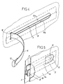
- the bag is made at from a tablecloth 2, simple or multilayer with at least the layer exterior is made of easily tearable synthetic material and for example, composed of a polyolefin and an ionomer.
- tablecloths and films are well known to those skilled in the art for their tearability, and it is not necessary to specify more the composition which varies according to manufacturers.
- the sheet is shaped into a sheath with connection of its longitudinal edges by means of a longitudinal weld 3.
- This sheath is then closed by a lower transverse weld 4 for form a pocket which, after filling, is closed by a weld upper transverse 5, juxtaposed or not, to a strip 6 forming handle.
- This headband, or the top of the bag is cut from the sheath during realization of the lower transverse weld 4 concerning the following bag.
- This bag is equipped with a reclosable closure composed of two elements 7 and 8 which, snapping into each other, are welded transversely at 7a and 8a against the internal face of the bag. These elements are, of course, arranged transversely near the upper weld 5.
- the bag comprises, in its part covering the junction zone 11 of the two elements 7 and 8 and near one of the sides of this zone, a 5 cutout 9 and, near the other side of the same area, a breakpoint 10.
- the cutout 9 is shaped semicircle whose concavity is facing the breakpoint 10. This semicircle is extended by two branches 9a, 9b which are substantially parallel between them and parallel to the junction zone 11 of the elements 7 and 8. In a variant not shown, this cut is in the shape of a cross or half cross.
- the breakpoint 10 is formed by a longitudinal weld not not extending beyond the junction zone of the two elements 7 and 8, but the length L is greater than the interval D between the two branches 9a, 9b of the cutting.
- the cutout 9 is covered by a fragment of adhesive tape 12 comprising, at its end which is opposite the stopping point 10, a tear-off tab 13, that is to say a tab whose face 13a is not covered with glue.
- Cutting 9 and welding 10 are carried out on the web 2 before conformation of the bag, and the fragment 12 of adhesive tape is placed on the cutting, before welding of elements 7 and 8 of the reclosable closure.
- This simple device seals the bag, while allowing to obtain a frank and clean opening, of length adapted to the needs.
- the web 2 is composed of an outer layer 2a which can be weakened by a laser beam, and by example in biaxially oriented polypropylene, polyester terephthalate, polyamide bioriented, and at least one other layer 2b which cannot be weakened by the same laser beam and, for example polyolefins. So when making by this bundle of microperforations 16, spaced apart to form dotted lines, only the outer layer 2a is affected. In this way, the inner layer or the other layers of the bag are not affected and ensure the sealing moisture.
- the microperforations are carried out as an extension of the branches of the cutout 9 which, as shown in FIG. 5, can also be produced by microperforations to suppress the cutting operation.
- the adhesive fragment 12 does not act on the tightness of the cut but remains the driving element generating the creation tear lines.
- the web 2 is also composed of an outer layer 2a which can be weakened by a beam laser and at least one non-embrittable layer 2b.
- the “U” cut 19 is delimited by perforations and is arranged in the middle of the junction 11 of the two elements 7 and 8 of the closure and at 90 ° relative to the previous embodiments, i.e. so as to be pulled longitudinally with respect to the bag 2 and not transversely.
- the ends of the cutout 19 are juxtaposed to the inner ends of two microperforation lines 20, produced by laser beam only in layer 2a of the sheet, and locally weakening the sheet, substantially above the junction zone 11.
- the cutout 19 is covered by a fragment 12 of adhesive tape with tear-off tab 13, closing the perforations in the cutout 19 and guaranteeing the waterproofness of the bag, while allowing its first opening.
- This first opening is carried out by pulling the tab 13 to tear the cut 19 to the microperforation lines 20 which yield, at less in their parts under the adhesive fragment 12. At this point it is possible to insert one or more fingers into the opening created for separate elements 7 and 8 from the closure and open the bag. Under these forces perpendicular to the sheets, the weakening lines give way to their outer ends 20a, forming a breakpoint, and allow access to content.
Landscapes
- Engineering & Computer Science (AREA)
- Mechanical Engineering (AREA)
- Bag Frames (AREA)
- Packages (AREA)
- Control And Other Processes For Unpacking Of Materials (AREA)
- Revetment (AREA)
- Package Closures (AREA)
Description
- d'une part, une découpe qui, formant amorce de rupture, est recouverte par un fragment de ruban adhésif avec languette d'arrachage,
- et, d'autre part, au moins un point d'arrêt limitant le déchirage du sac dans sa partie couvrant la zone de jonction des éléments de la fermeture refermable.
Claims (8)
- Sac refermable étanche à ouverture par déchirage limité comprenant une fermeture encliquetable et refermable composée de deux éléments (7, 8) fixés transversalement contre la paroi du sac à l'intérieur de celui-ci, et muni chacun de moyens aptes à s'emboíter élastiquement dans des moyens complémentaires de l'autre élément, caractérisé en ce qu'il est réalisé dans une nappe (2), comportant, dans sa partie couvrant une zone de jonction (11) des deux éléments (7, 8) de la fermeture refermable :d'une part, une découpe (9, 19) qui, formant amorce de rupture, est recouverte par un fragment (12) de ruban adhésif avec languette d'arrachage (13),et, d'autre part, un point d'arrêt (10), limitant le déchirage du sac à sa partie couvrant la zone de jonction (11) des éléments de la fermeture refermable.
- Sac refermable étanche selon la revendication 1, caractérisé en ce que la découpe (9) est disposée latéralement d'un côté de la zone de jonction (11) des deux éléments (7, 8) de fermeture refermable, tandis que le point d'arrêt (10) est disposé du côté opposé.
- Sac refermable étanche selon la revendication 2, caractérisé en ce que la découpe (9) est en forme de demi-cercle dont la concavité est tournée vers le point d'arrêt (10) et présente deux branches (9a, 9b) sensiblement parallèles entre elles et à la zone (11) de jonction des éléments (7 et 8) de la fermeture refermable.
- Sac refermable étanche selon l'ensemble des revendications 1 et 2, caractérisé en ce que le point d'arrêt (10) est constitué par une soudure longitudinale dont la longueur (L) est supérieure à l'intervalle (D) entre les branches (9a, 9b) de la découpe (9), mais inférieure à la largeur des deux éléments (7, 8) de la fermeture refermable.
- Sac refermable selon la revendication 2, caractérisé en ce que la nappe (2) ou au moins la couche extérieure de cette nappe est réalisée dans une matière synthétique aisément déchirable et, par exemple, composée d'une polyoléfine et d'un ionomère.
- Sac refermable selon la revendication 2, caractérisé en ce que la nappe (2) est composée d'une couche extérieure (2a) en matière synthétique fragilisable par un faisceau laser et d'au moins une autre couche (2b) en une matière non fragilisable par ce faisceau, et comporte, au moins dans le prolongement de la découpe (9) et jusqu'au point d'arrêt (10), deux lignes de microperforations (16) espacées réalisées par faisceau laser dans la seule couche extérieure (2a) de la nappe.
- Sac refermable selon la revendication 6, caractérisé en ce que la découpe (9) est également réalisée par microperforations de la couche extérieure (2a) de la nappe.
- Sac refermable selon la revendication 1, caractérisé en ce que la découpe (19) est disposée au milieu de la zone de jonction des deux éléments (7, 8) de fermeture refermable, tandis que les points d'arrêt sont constitués par les extrémités (20a) de deux lignes de microperforations (20), réalisées dans la couche extérieure (2a) de la nappe, de part et d'autre de la découpe (19), au-dessus de la zone de jonction (11) des deux éléments de fermeture et constituant lignes de fragilisation.
Applications Claiming Priority (2)
| Application Number | Priority Date | Filing Date | Title |
|---|---|---|---|
| FR9808716 | 1998-07-03 | ||
| FR9808716A FR2780704B1 (fr) | 1998-07-03 | 1998-07-03 | Sac refermable etanche |
Publications (2)
| Publication Number | Publication Date |
|---|---|
| EP0968928A1 EP0968928A1 (fr) | 2000-01-05 |
| EP0968928B1 true EP0968928B1 (fr) | 2003-03-19 |
Family
ID=9528389
Family Applications (1)
| Application Number | Title | Priority Date | Filing Date |
|---|---|---|---|
| EP99420148A Expired - Lifetime EP0968928B1 (fr) | 1998-07-03 | 1999-06-29 | Sac refermable étanche |
Country Status (5)
| Country | Link |
|---|---|
| EP (1) | EP0968928B1 (fr) |
| AT (1) | ATE234764T1 (fr) |
| DE (1) | DE69905984D1 (fr) |
| ES (1) | ES2192026T3 (fr) |
| FR (1) | FR2780704B1 (fr) |
Cited By (2)
| Publication number | Priority date | Publication date | Assignee | Title |
|---|---|---|---|---|
| US7651290B2 (en) | 2005-05-09 | 2010-01-26 | Kimberly-Clark Worldwide, Inc. | Device with pull tab activation |
| US7950864B2 (en) | 2005-12-13 | 2011-05-31 | Kimberly-Clark Worldwide, Inc. | Device with internal pull tab activation |
Families Citing this family (4)
| Publication number | Priority date | Publication date | Assignee | Title |
|---|---|---|---|---|
| FR2816597B1 (fr) | 2000-11-15 | 2003-06-13 | Autobar Flexible France | Sac d'emballage |
| EP1477424A1 (fr) * | 2003-05-13 | 2004-11-17 | The Procter & Gamble Company | Emballage pour articles plats et compressibles |
| JP4526884B2 (ja) | 2004-06-28 | 2010-08-18 | 出光ユニテック株式会社 | チャックテープ付き袋 |
| US9108770B2 (en) * | 2013-06-24 | 2015-08-18 | C-P Converters, Inc. | Re-sealable packaging |
Family Cites Families (3)
| Publication number | Priority date | Publication date | Assignee | Title |
|---|---|---|---|---|
| CA2070937C (fr) * | 1991-08-09 | 1998-09-15 | Paul Tilman | Sacs de plastique reutilisables et methode de fabrication au moyen d'une bande dechirable discontinue |
| US20020020481A1 (en) * | 1995-05-11 | 2002-02-21 | William A. Bodolay | Tamper-evident container with reclosable fastener and method for making |
| BR9510628A (pt) * | 1995-08-09 | 1999-11-30 | James Worth Yeager | Filme com fecho corredico automático e saco. |
-
1998
- 1998-07-03 FR FR9808716A patent/FR2780704B1/fr not_active Expired - Fee Related
-
1999
- 1999-06-29 DE DE69905984T patent/DE69905984D1/de not_active Expired - Lifetime
- 1999-06-29 ES ES99420148T patent/ES2192026T3/es not_active Expired - Lifetime
- 1999-06-29 EP EP99420148A patent/EP0968928B1/fr not_active Expired - Lifetime
- 1999-06-29 AT AT99420148T patent/ATE234764T1/de not_active IP Right Cessation
Cited By (2)
| Publication number | Priority date | Publication date | Assignee | Title |
|---|---|---|---|---|
| US7651290B2 (en) | 2005-05-09 | 2010-01-26 | Kimberly-Clark Worldwide, Inc. | Device with pull tab activation |
| US7950864B2 (en) | 2005-12-13 | 2011-05-31 | Kimberly-Clark Worldwide, Inc. | Device with internal pull tab activation |
Also Published As
| Publication number | Publication date |
|---|---|
| FR2780704A1 (fr) | 2000-01-07 |
| EP0968928A1 (fr) | 2000-01-05 |
| ES2192026T3 (es) | 2003-09-16 |
| FR2780704B1 (fr) | 2000-09-15 |
| ATE234764T1 (de) | 2003-04-15 |
| DE69905984D1 (de) | 2003-04-24 |
Similar Documents
| Publication | Publication Date | Title |
|---|---|---|
| CA2237427C (fr) | Enceinte etanche et procede de conditionnement d'un liquide dans cette enceinte | |
| FR2837468A1 (fr) | Dispositifs barrieres pour sacs en plastique | |
| FR2727091A1 (fr) | Sac d'emballage | |
| EP0631560B1 (fr) | Emballage fabrique a partir d'une feuille mince plissee formant un sachet pour produits en vrac | |
| WO2004037664A1 (fr) | Emballage souple refermable | |
| EP0968928B1 (fr) | Sac refermable étanche | |
| EP0748745A1 (fr) | Dispositif d'ouverture d'un sachet d'emballage en film mince | |
| EP1697230A1 (fr) | Dispositif pour ouvrir et eventuellement fermer un conditionnement | |
| FR2816597A1 (fr) | Sac d'emballage | |
| EP0270455B1 (fr) | Sac en matière plastique avec bande de fermeture adhésive | |
| EP1254846A1 (fr) | Emballage souple refermable | |
| EP0894072B1 (fr) | Emballage gonflable | |
| EP1103487B1 (fr) | Sachet d'emballage à ouverture refermable | |
| FR2857338A1 (fr) | Sac a aliments avec bec verseur | |
| FR2611183A1 (fr) | Boite pliante | |
| FR2888571A1 (fr) | Element pour la realisation d'un emballage de conditionnement d'un produit alimentaire, emballage correspondant, et ensemble comprenant un tel emballage et un produit alimentaire | |
| EP3144238B1 (fr) | Emballage et flan pour emballage avec dispositif d'ouverture perfectionné | |
| EP0193477B1 (fr) | Sac en papier dont un fond est équipé d'une valve de remplissage | |
| FR2727088A1 (fr) | Dispositif de fermeture et d'ouverture d'un emballage comportant un sachet | |
| FR2639917A1 (fr) | Emballage parallelepipedique a couvercle refermable, flan propre a la constitution d'un tel emballage, et ebauche d'emballage correspondante | |
| FR2810966A1 (fr) | Emballage souple refermable | |
| EP1261525A1 (fr) | Boite etanche a fenetre | |
| FR2806384A1 (fr) | Dispositif de fermeture de sacs en matiere plastique pour la collecte de produits divers et notamment de dechets hospitaliers | |
| FR2713203A1 (fr) | Enveloppe de sécurité. | |
| FR2752226A1 (fr) | Emballage pourvu d'une enveloppe souple interne et son procede de fabrication |
Legal Events
| Date | Code | Title | Description |
|---|---|---|---|
| PUAI | Public reference made under article 153(3) epc to a published international application that has entered the european phase |
Free format text: ORIGINAL CODE: 0009012 |
|
| AK | Designated contracting states |
Kind code of ref document: A1 Designated state(s): AT BE CH CY DE DK ES FI FR GB GR IE IT LI LU MC NL PT SE |
|
| AX | Request for extension of the european patent |
Free format text: AL;LT;LV;MK;RO;SI |
|
| RAP3 | Party data changed (applicant data changed or rights of an application transferred) |
Owner name: AUTOBAR FLEXIBLE FRANCE |
|
| 17P | Request for examination filed |
Effective date: 20000216 |
|
| AKX | Designation fees paid |
Free format text: AT BE CH CY DE DK ES FI FR GB GR IE IT LI LU MC NL PT SE |
|
| 17Q | First examination report despatched |
Effective date: 20020125 |
|
| GRAH | Despatch of communication of intention to grant a patent |
Free format text: ORIGINAL CODE: EPIDOS IGRA |
|
| GRAH | Despatch of communication of intention to grant a patent |
Free format text: ORIGINAL CODE: EPIDOS IGRA |
|
| GRAA | (expected) grant |
Free format text: ORIGINAL CODE: 0009210 |
|
| AK | Designated contracting states |
Designated state(s): AT BE CH CY DE DK ES FI FR GB GR IE IT LI LU MC NL PT SE |
|
| PG25 | Lapsed in a contracting state [announced via postgrant information from national office to epo] |
Ref country code: IT Free format text: LAPSE BECAUSE OF FAILURE TO SUBMIT A TRANSLATION OF THE DESCRIPTION OR TO PAY THE FEE WITHIN THE PRESCRIBED TIME-LIMIT;WARNING: LAPSES OF ITALIAN PATENTS WITH EFFECTIVE DATE BEFORE 2007 MAY HAVE OCCURRED AT ANY TIME BEFORE 2007. THE CORRECT EFFECTIVE DATE MAY BE DIFFERENT FROM THE ONE RECORDED. Effective date: 20030319 Ref country code: IE Free format text: LAPSE BECAUSE OF FAILURE TO SUBMIT A TRANSLATION OF THE DESCRIPTION OR TO PAY THE FEE WITHIN THE PRESCRIBED TIME-LIMIT Effective date: 20030319 Ref country code: GR Free format text: LAPSE BECAUSE OF FAILURE TO SUBMIT A TRANSLATION OF THE DESCRIPTION OR TO PAY THE FEE WITHIN THE PRESCRIBED TIME-LIMIT Effective date: 20030319 Ref country code: GB Free format text: LAPSE BECAUSE OF FAILURE TO SUBMIT A TRANSLATION OF THE DESCRIPTION OR TO PAY THE FEE WITHIN THE PRESCRIBED TIME-LIMIT Effective date: 20030319 Ref country code: FI Free format text: LAPSE BECAUSE OF FAILURE TO SUBMIT A TRANSLATION OF THE DESCRIPTION OR TO PAY THE FEE WITHIN THE PRESCRIBED TIME-LIMIT Effective date: 20030319 Ref country code: AT Free format text: LAPSE BECAUSE OF FAILURE TO SUBMIT A TRANSLATION OF THE DESCRIPTION OR TO PAY THE FEE WITHIN THE PRESCRIBED TIME-LIMIT Effective date: 20030319 |
|
| REG | Reference to a national code |
Ref country code: GB Ref legal event code: FG4D Free format text: NOT ENGLISH |
|
| REG | Reference to a national code |
Ref country code: CH Ref legal event code: EP |
|
| REG | Reference to a national code |
Ref country code: IE Ref legal event code: FG4D Free format text: FRENCH |
|
| REF | Corresponds to: |
Ref document number: 69905984 Country of ref document: DE Date of ref document: 20030424 Kind code of ref document: P |
|
| PG25 | Lapsed in a contracting state [announced via postgrant information from national office to epo] |
Ref country code: SE Free format text: LAPSE BECAUSE OF FAILURE TO SUBMIT A TRANSLATION OF THE DESCRIPTION OR TO PAY THE FEE WITHIN THE PRESCRIBED TIME-LIMIT Effective date: 20030619 Ref country code: DK Free format text: LAPSE BECAUSE OF FAILURE TO SUBMIT A TRANSLATION OF THE DESCRIPTION OR TO PAY THE FEE WITHIN THE PRESCRIBED TIME-LIMIT Effective date: 20030619 |
|
| PG25 | Lapsed in a contracting state [announced via postgrant information from national office to epo] |
Ref country code: PT Free format text: LAPSE BECAUSE OF FAILURE TO SUBMIT A TRANSLATION OF THE DESCRIPTION OR TO PAY THE FEE WITHIN THE PRESCRIBED TIME-LIMIT Effective date: 20030620 |
|
| PG25 | Lapsed in a contracting state [announced via postgrant information from national office to epo] |
Ref country code: DE Free format text: LAPSE BECAUSE OF FAILURE TO SUBMIT A TRANSLATION OF THE DESCRIPTION OR TO PAY THE FEE WITHIN THE PRESCRIBED TIME-LIMIT Effective date: 20030621 |
|
| PG25 | Lapsed in a contracting state [announced via postgrant information from national office to epo] |
Ref country code: LU Free format text: LAPSE BECAUSE OF NON-PAYMENT OF DUE FEES Effective date: 20030629 Ref country code: CY Free format text: LAPSE BECAUSE OF FAILURE TO SUBMIT A TRANSLATION OF THE DESCRIPTION OR TO PAY THE FEE WITHIN THE PRESCRIBED TIME-LIMIT Effective date: 20030629 |
|
| PG25 | Lapsed in a contracting state [announced via postgrant information from national office to epo] |
Ref country code: MC Free format text: LAPSE BECAUSE OF NON-PAYMENT OF DUE FEES Effective date: 20030630 Ref country code: LI Free format text: LAPSE BECAUSE OF NON-PAYMENT OF DUE FEES Effective date: 20030630 Ref country code: CH Free format text: LAPSE BECAUSE OF NON-PAYMENT OF DUE FEES Effective date: 20030630 |
|
| REG | Reference to a national code |
Ref country code: ES Ref legal event code: FG2A Ref document number: 2192026 Country of ref document: ES Kind code of ref document: T3 |
|
| GBV | Gb: ep patent (uk) treated as always having been void in accordance with gb section 77(7)/1977 [no translation filed] |
Effective date: 20030319 |
|
| REG | Reference to a national code |
Ref country code: IE Ref legal event code: FD4D Ref document number: 0968928E Country of ref document: IE |
|
| PLBE | No opposition filed within time limit |
Free format text: ORIGINAL CODE: 0009261 |
|
| STAA | Information on the status of an ep patent application or granted ep patent |
Free format text: STATUS: NO OPPOSITION FILED WITHIN TIME LIMIT |
|
| REG | Reference to a national code |
Ref country code: CH Ref legal event code: PL |
|
| 26N | No opposition filed |
Effective date: 20031222 |
|
| REG | Reference to a national code |
Ref country code: FR Ref legal event code: TP Ref country code: FR Ref legal event code: CD |
|
| PGFP | Annual fee paid to national office [announced via postgrant information from national office to epo] |
Ref country code: ES Payment date: 20080620 Year of fee payment: 10 |
|
| PGFP | Annual fee paid to national office [announced via postgrant information from national office to epo] |
Ref country code: NL Payment date: 20080521 Year of fee payment: 10 |
|
| PGFP | Annual fee paid to national office [announced via postgrant information from national office to epo] |
Ref country code: BE Payment date: 20080710 Year of fee payment: 10 |
|
| BERE | Be: lapsed |
Owner name: *AUTOBAR FLEXIBLE FRANCE Effective date: 20090630 |
|
| NLV4 | Nl: lapsed or anulled due to non-payment of the annual fee |
Effective date: 20100101 |
|
| PG25 | Lapsed in a contracting state [announced via postgrant information from national office to epo] |
Ref country code: BE Free format text: LAPSE BECAUSE OF NON-PAYMENT OF DUE FEES Effective date: 20090630 |
|
| PG25 | Lapsed in a contracting state [announced via postgrant information from national office to epo] |
Ref country code: NL Free format text: LAPSE BECAUSE OF NON-PAYMENT OF DUE FEES Effective date: 20100101 |
|
| REG | Reference to a national code |
Ref country code: ES Ref legal event code: FD2A Effective date: 20090630 |
|
| PG25 | Lapsed in a contracting state [announced via postgrant information from national office to epo] |
Ref country code: ES Free format text: LAPSE BECAUSE OF NON-PAYMENT OF DUE FEES Effective date: 20090630 |
|
| REG | Reference to a national code |
Ref country code: FR Ref legal event code: PLFP Year of fee payment: 18 |
|
| REG | Reference to a national code |
Ref country code: FR Ref legal event code: PLFP Year of fee payment: 19 |
|
| REG | Reference to a national code |
Ref country code: FR Ref legal event code: PLFP Year of fee payment: 20 |
|
| PGFP | Annual fee paid to national office [announced via postgrant information from national office to epo] |
Ref country code: FR Payment date: 20180628 Year of fee payment: 20 |